1
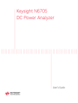
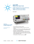
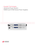
Keysight Series N6700
Low-Profile Modular
Power System
User’s Guide
Legal Notices
© Keysight Technologies 2006 - 2015
No part of this document may be
photocopied, reproduced, or translated to
another language without the prior
agreement and written consent of Keysight
Technologies as governed by United States
and international copyright laws.
Warranty
The material contained in this document is
provided “as is,” and is subject to being
changed, without notice, in future editions.
Further, to the maximum extent permitted
by applicable law, Keysight disclaims all
warranties, either express or implied, with
regard to this manual and any information
contained herein, including but not limited
to the implied warranties of merchantability
and fitness for a particular purpose.
Keysight shall not be liable for errors or for
incidental or consequential damages in
connection with the furnishing, use, or
performance of this document or of any
information contained herein. Should
Keysight and the user have a separate
written agreement with warranty terms
covering the material in this document that
conflict with these terms, the warranty
terms in the separate agreement shall
control.
Manual Editions
Manual Part Number: 5969-2937
Edition 8, January 2015
Printed in Malaysia.
Reprints of this manual containing minor
corrections and updates may have the
same printing date. Revised editions are
identified by a new printing date. .
Declaration of Conformity
Declarations of Conformity for this product
and for other Keysight products may be
downloaded from the Web. Go to
http://www.keysight.com/go/conformity
and click on “Declarations of Conformity.”
You can then search by product number to
find the latest Declaration of Conformity
2
Waste Electrical and
Electronic Equipment (WEEE)
Directive 2002/96/EC
This product complies with the WEEE
Directive 2002/96/EC) marketing
requirement. The affixed product label (see
below) indicates that you must not discard
this electrical/electronic product in
domestic household waste.
Product Category: With reference to the
equipment types in the WEEE directive
Annex 1, this product is classified as
“Monitoring and Control instrumentation”
product.
Do not dispose in domestic household
waste.
To return unwanted products, contact our
local Keysight office, or see
www.keysight.com/environment/product
for more information.
Certification
Keysight Technologies certifies that this
product met its published specifications at
time of shipment from the factory. Keysight
Technologies further certifies that its
calibration measurements are traceable to
the United States National Institute of
Standards and Technology, to the extent
allowed by the Institute's calibration
facility, and to the calibration facilities of
other International Standards Organization
members.
Assistance
This product comes with the standard
product warranty. Warranty options,
extended support contacts, product
maintenance agreements and customer
assistance agreements are also available.
Contact your nearest Keysight
Technologies Sales and Service office for
further information on Keysight
Technologies' full line of Support Programs.
Technologies Licenses
The hardware and or software described in
this document are furnished under a
license and may be used or copied only in
accordance with the terms of such license.
U.S. Government Restricted Rights
Software and technical data rights granted
to the federal government include only
those rights customarily provided to end
user customers. Keysight provides this
customary commercial license in Software
and technical data pursuant to FAR 12.211
(Technical Data) and 12.212 (Computer
Software) and, for the Department of
Defense, DFARS 252.227-7015 (Technical
Data – Commercial Items) and DFARS
227.7202-3 (Rights in Commercial
Computer Software or Computer Software
Documentation).
Trademarks
Microsoft and Windows are U.S. registered
trademarks of Microsoft Corporation.
Exclusive Remedies
THE REMEDIES PROVIDED HEREIN ARE
THE CUSTOMER'S SOLE AND EXCLUSIVE
REMEDIES. KEYSIGHT TECHNOLOGIES
SHALL NOT BE LIABLE FOR ANY DIRECT,
INDIRECT, SPECIAL, INCIDENTAL, OR
CONSEQUENTIAL DAMAGES, WHETHER
BASED ON CONTRACT, TORT, OR ANY
OTHER LEGAL THEORY.
Keysight N6700 User’s Guide
Safety Notices
The following general safety precautions
must be observed during all phases of
operation of this instrument. Failure to
comply with these precautions or with
specific warnings or instructions elsewhere
in this manual violates safety standards of
design, manufacture, and intended use of
the instrument. Keysight Technologies
assumes no liability for the customer's
failure to comply with these requirements.
General
Do not use this product in any manner not
specified by the manufacturer. The
protective features of this product may be
impaired if it is used in a manner not
specified in the operation instructions.
Before Applying Power
Verify that all safety precautions are taken.
Make all connections to the unit before
applying power. Note the instrument's
external markings described under "Safety
Symbols"
Ground the Instrument
This product is a Safety Class 1 instrument
(provided with a protective earth terminal).
To minimize shock hazard, the instrument
chassis and cover must be connected to an
electrical ground. The instrument must be
connected to the AC power mains through
a grounded power cable, with the ground
wire firmly connected to an electrical
ground (safety ground) at the power outlet.
Any interruption of the protective
(grounding) conductor or disconnection of
the protective earth terminal will cause a
potential shock hazard that could result in
personal injury.
Fuses
The instrument contains an internal fuse,
which is not customer accessible.
Keysight N6700 User’s Guide
Do Not Operate in an Explosive
Atmosphere
Safety Symbols
Direct current
Do not operate the instrument in the
presence of flammable gases or fumes.
Alternating current
Do Not Remove the Instrument
Cover
Both direct and alternating
current
Only qualified, service-trained personnel
who are aware of the hazards involved
should remove instrument covers. Always
disconnect the power cable and any
external circuits before removing the
instrument cover.
Three phase alternating
current
Do Not Modify the Instrument
Earth (ground) terminal
Protective earth ground
terminal.
Do not install substitute parts or perform
any unauthorized modification to the
product. Return the product to a Keysight
Sales and Service Office for service and
repair to ensure that safety features are
maintained.
Frame or chassis terminal
In Case of Damage
Neutral conductor on
permanently installed
equipment
Instruments that appear damaged or
defective should be made inoperative and
secured against unintended operation until
they can be repaired by qualified service
personnel.
CAUTION
A CAUTION notice denotes a hazard. It
calls attention to an operating
procedure, practice, or the like that, if
not correctly performed or adhered to,
could result in damage to the product
or loss of important data. Do not
proceed beyond a CAUTION notice
until the indicated conditions are fully
understood and met.
WARNING
A WARNING notice denotes a hazard.
It calls attention to an operating
procedure, practice, or the like that, if
not correctly performed or adhered to,
could result in personal injury or
death. Do not proceed beyond a
WARNING notice until the indicated
conditions are fully understood and
met.
Terminal is at earth
potential.
Line conductor on
permanently installed
equipment.
On supply
Off supply
Standby supply. Unit is not
completely disconnected
from AC mains when switch
is off
In position of a bi-stable
push switch
Out position of a bi-stable
push switch
Caution, risk of electric
shock
Caution, hot surface
Caution, refer to
accompanying description
3
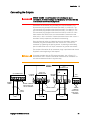
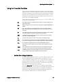
In this Book
Specific chapters in this manual contain the following information:
Quick Reference – Chapter 1 is a quick reference section that helps
you quickly become familiar with your Keysight N6700 Modular
Power System. It describes the differences between the various
modules in the power system.
Installation – Chapter 2 describes how to install your power system.
It describes how to connect various loads to the output. It discusses
remote sensing as well as parallel and series operation.
Getting Started – Chapter 3 describes how to set the voltage,
current, over-voltage protection, and turn on the output. It also
describes how to configure the remote interface.
Operating the Power System – Chapter 4 describes how to use the
advanced features of the power system using the front panel menus
and the corresponding SCPI commands.
Specifications – Appendix A describes the mainframe characteristics.
Using the Digital Port – Appendix B describes how to configure and
use the digital port on the back of the instrument.
Power Allocation – Appendix C describes the power allocation
function, which applies to power system in which the combined
ratings of the power modules exceed the power rating of the
mainframe.
Output On/Off Synchronization – Appendix D discusses output
on/off synchronization, which lets you accurately synchronize output
turn-on sequences across multiple mainframes.
Source Operating Modes – Appendix E discusses operating mode
information for all power modules.
For complete details on the SCPI (Standard Commands for
Programmable Instruments) commands, refer to the N6700
Programmer’s Reference Help file included on the Keysight N6700
Product Reference CD. This CD-ROM is shipped along with your
instrument.
NOTE
4
You can contact Keysight Technologies at one of the following telephone
numbers for warranty, service, or technical support information.
In the United States: (800) 829-4444
In Europe: 31 20 547 2111
In Japan: 0120-421-345
Or use our Web link for information on contacting Keysight in your
country or specific location: www.keysight.com/find/assist
Or contact your Keysight Technologies Representative.
Keysight N6700 User’s Guide
Contents
1 – Quick Reference....................................................................................................... 7
The Keysight N6700 Modular Power System – At a Glance ........... 8
The Front Panel – At a Glance ....................................................... 11
The Rear Panel – At a Glance ........................................................ 11
Front Panel Display – At a Glance ................................................. 12
Front Panel Keys – At a Glance ..................................................... 13
Front Panel Menu Reference ......................................................... 14
SCPI Command Summary ............................................................. 16
2 – Installation ............................................................................................................. 23
General Information ....................................................................... 24
Inspecting the Unit ......................................................................... 25
Installing the Unit ........................................................................... 26
Connecting the Line Cord .............................................................. 30
Connecting the Outputs ................................................................. 31
Remote Sense Connections ........................................................... 36
Parallel Connections ...................................................................... 38
Series Connections......................................................................... 40
Additional Load Considerations ..................................................... 42
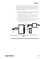
Connecting the Auxiliary Voltage Measurement Input ................. 44
3 – Getting Started ...................................................................................................... 45
Turning the Unit On ........................................................................ 46
Selecting an Output Channel ......................................................... 46
Entering an Output Voltage Setting .............................................. 46
Entering a Current Limit Setting .................................................... 47
Enabling the Output ....................................................................... 47
Using the Front Panel Menu .......................................................... 48
Connecting to the Interfaces ......................................................... 50
Communicating Over the LAN ....................................................... 57
Securing the Interfaces .................................................................. 59
4 – Operating the Power System ................................................................................. 61
Programming the Output ............................................................... 62
Synchronizing Output Steps .......................................................... 68
Programming Output Lists ............................................................. 72
Making Measurements ................................................................... 77
Using the Digitizer .......................................................................... 79
Using the Protection Functions ..................................................... 87
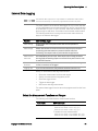
External Data Logging.................................................................... 91
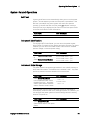
System-Related Operations ........................................................... 95
Keysight N6700 User’s Guide
5
A – Specifications ........................................................................................................ 99
Keysight N6700B, N6701A, N6702A MPS Mainframes .............. 100
B – Using the Digital Port .......................................................................................... 103
Digital Control Port ......................................................................104
Configuring the Digital Control Port ............................................105
C – Power Allocation ................................................................................................. 109
Power Limit Operation .................................................................110
Module Power Allocation .............................................................111
D – Output On/Off Synchronization ........................................................................... 113
Synchronizing Output Turn-on Delays ........................................114
Synchronizing Multiple Mainframes ............................................117
Operation ......................................................................................118
E – Source Operating Modes ..................................................................................... 119
Single Quadrant Operation ..........................................................120
Keysight N678xA Multi-Quadrant Operation ..............................122
Updates
This manual describes firmware revision D.03.08 and up. Go to
http://www.keysight.com/find/N6700firmware if you need to download
this or any later versions of the firmware. Information on how to install
the firmware is available on the web site.
Refer to “Instrument Identification” in chapter 4 to view the firmware
version that is currently installed in your mainframe.
Updated versions of this manual are also posted on the web. Go to
http://www.keysight.com/find/N6700 to get the latest version of the
manual.
6
Keysight N6700 User’s Guide
1
Quick Reference
The Keysight N6700 Modular Power System – At a Glance ........... 8
The Front Panel – At a Glance ....................................................... 11
The Rear Panel – At a Glance ........................................................ 11
Front Panel Display – At a Glance ................................................. 12
Front Panel Keys – At a Glance ..................................................... 13
Front Panel Menu Reference ......................................................... 14
SCPI Command Summary ............................................................. 16
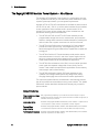
This chapter concisely describes the operation of the Keysight N6700
Modular Power System (MPS).
This chapter does not describe every operating feature in detail. It is
simply a quick reference guide to quickly become familiar with the
essential operating features of the power system.
For complete details on the SCPI (Standard Commands for
Programmable Instruments) commands, refer to the Programmer’s
Reference Help file included on the Keysight N6700 Product Reference
CD. This CD-ROM is shipped along with your instrument.
NOTE
Unless otherwise noted, the Keysight N6700 Modular Power System will
also be referred to as “MPS” and “power system” throughout this
manual.
1
Quick Reference
The Keysight N6700 Modular Power System – At a Glance
The Keysight N6700 Modular Power System is a configurable, one rackunit (1U) platform that lets you mix and match power modules to create
a power system optimized for your test system requirements.
Keysight N6700–N6702 MPS mainframes are available in power levels of
400 W, 600 W, and 1,200 W. Up to four power modules can be installed
in each mainframe. Power modules come in power levels of 20 W
through 500 W, have various voltage and current combinations, and
provide the following performance features:
The N673xB, N674xB, and N677xA DC Power Modules provide
programmable voltage and current, measurement, and protection
features, making these economical models suitable for powering the
device-under-test or system resources such as fixture controls.
The N675xA High-Performance, Autoranging DC Power Modules
provide low noise, high accuracy, fast programming times, and
advanced programming and measurement capabilities to speed test
throughput.
The N676xA Precision DC Power Modules provide precise control
and measurements in the milli- and micro-ampere region with the
ability to simultaneously digitize voltage and current and capture
those measurements into an oscilloscope-like data buffer.
The N678xA Source/Measure Units (SMU) have a multiple-quadrant
power mesh with separate voltage and current priority source
modes. These models are optimized for applications such as battery
drain analysis and functional testing.
The N6783A Application-Specific DC Power Modules are twoquadrant low-wattage models specifically designed for battery
charging/discharging and mobile communications applications.
The output and system features are described in the following sections.
Not all output features are available on every power module. The “Model
Differences” section describes the features that apply only to specific
power modules.
Output Features
Programmable voltage Full programming capability is provided for the entire range of output
voltage and current. Outputs can operate as either constant voltage (CV) or
and current
constant current (CC) sources.
Low output noise
Available on Keysight N676xA and N675xA power modules. Output noise is
<4.5 mV peak-to-peak, which is comparable to linear supplies.
Fast up/down
programming
Available on Keysight N675xA, N676xA, and N678xA SMU power modules.
≤1.5 millisecond response time from 10% to 90% of the output rating.
Fast transient response Available on Keysight N675xA, N676xA, and N678xA SMU power modules.
Transient response is less than 100 μs.
8
Keysight N6700 User’s Guide
Quick Reference
1
Output autoranging
capability
Available on Keysight N676xA and N675xA power modules.
Autoranging supplies the maximum rated power over a continuous range of
voltage and current settings.
Output On/Off
sequencing
A turn-on/turn-off delay capability for each output allows output on/off
sequencing.
Remote voltage sensing Two remote sensing terminals are provided for each output. When shipped,
the remote sense jumpers are included in a separate bag. See Chapter 2.
Output protection
Each output has over-voltage, over-current, and over-temperature
protection. Over-voltage and over-current protection are programmable.
Multiple-Quadrant
operation
Available on Keysight N678xA SMU and N6783A power modules.
2- quadrant operation provides source and sink output capability. Keysight
model N6784A offers 4- quadrant output operation.
Measurement Features
Multiple-output/Single- Switch between a 4-output summary view and a 1-output detailed view of
power supply information. All power modules display real-time output
output meter display
voltage and current measurements as well as status information.
Seamless measurement Available on Keysight N6781A, N6782A, N6785A, and N6786A SMU power
modules. Output measurements seamlessly autorange between ranges –
autoranging
however, the 10 μA current range must be selected manually.
Microampere current
measurements
Available on Keysight N6761A, N6762A, and N678xA SMU power modules.
Current measurement can be made as low as 1 μA in the 10 μA range.
Fast digitizing
Available on Keysight N678xA SMU power modules.
5.12 μs/sample for one parameter; 10.24 μs/sample for two parameters.
System Features
Choice of three
interfaces
GPIB (IEEE-488), LAN, and USB remote programming interfaces are built in.
Built-in Web server
A built-in Web server lets you control the instrument directly from an
internet browser on your computer.
SCPI language
The instrument is compatible with the Standard Commands for
Programmable Instruments (SCPI).
Front panel I/O setup
Menus let you set up GPIB and LAN parameters from the front panel.
Real-time status
information
The front panel indicates the status of each output. It also indicates when a
protection shut-down has occurred.
Module identification
Each module has identifying data stored in non-volatile memory.
Information includes model number, serial number, and options.
Universal AC input
Mainframes have universal input voltage capability with active power factor
correction.
Keysight N6700 User’s Guide
9
1
Quick Reference
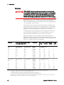
Model Differences
Feature
(● = available)
DC Power
High-Performance
Precision
N673xB, N674xB, N677xA
N675xA
N676xA
N6731B – N6736B
N6741B – N6746B
N6773A – N6777A
N6751A
N6752A
N6753A, N6754A
N6755A, N6756A
N6761A
N6762A
N6763A, N6764A
N6765A, N6766A
Option 761
Option 760
Option 761
Option 760
●
Option 761
Option 760
●
50 W output rating
100 W output rating
300 W output rating
500 W output rating
Output disconnect relays
Output disconnect/polarity reversal relays NOTE 1
Autoranging output capability
Voltage or current turn-on priority
N6761A, N6762A
●
Precision voltage and current measurements
Low voltage and low current output range
N6761A, N6762A
●
Low voltage and low current measurement range
200 microampere measurement range NOTE 2
Option 2UA
●
Simultaneous voltage and current measurements
SCPI command output list capability NOTE 3
SCPI command array readback NOTE 3
SCPI command programmable sample rate NOTE 3
SCPI command external data logging NOTE 3
Double-wide (occupies 2 channel locations)
Option 054
Option 054
Option 054
Option 054
Feature
(● = available)
N6781A
Output rating
2-quadrant operation
20 W
●
Option 054
Option 054
Option 054
Option 054
N6753A – N6756A
●
●
●
●
N6763A – N6766A
Source/Measure Units (SMU)
Application-Specific
N6782A N6784A
N6783A
BAT
N6783A
MFG
24 W
●
18 W
●
20 W
●
N6785A N6786A
20 W
80 W
●
80 W
●
●
4-quadrant operation
Auxiliary voltage measurement input
●
Output disconnect relays
Negative voltage protection
Voltage or current priority mode
●
●
●
Programmable output resistance
●
Multiple voltage output ranges
3
3
3
4
4
Multiple current output ranges
3
3
4
4
4
Multiple voltage measurement ranges
3
3
3
Multiple current measurement ranges
Simultaneous voltage and current measurements
4
●
4
●
4
●
3
●
3
●
Seamless measurement autoranging
●
●
●
●
●
●
●
●
●
●
●
●
●
●
●
●
●
●
●
●
●
●
SCPI command output list capability
SCPI command array readback NOTE 3
SCPI command programmable sample rate NOTE 3
SCPI command external data logging NOTE 3
Double-wide (occupies 2 channel locations)
NOTE 3, 4
●
●
●
●
●
●
●
●
●
●
●
●
●
Option 761 Option 761
●
●
●
●
●
●
●
2
2
●
●
●
●
●
●
●
●
1
Output current is limited to 10A max. on Models N6742B and N6773A with Option 760.
Option 760 is not available on Models N6741B, N6751A, N6752A, N6761A, and N6762A.
2
Option 2UA.is only available on Models N6761A and N6762A. It includes Option 761.
3
Only available when using the remote interfaces; not from the front panel.
4
List capability is not available on the negative current output on Model N6783A
10
Keysight N6700 User’s Guide
Quick Reference
1
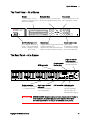
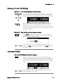
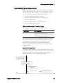
The Front Panel – At a Glance
Display
Navigation keys
Output keys
Turns off after 1 hour of
Move the cursor to a menu item. Turn the outputs on or off.
inactivity. Press any key to Select the highlighted menu item. Enter voltage or current.
restore the display.
N6700B
Meter
Low-Profile MPS
Mainframe
600 Watt
o
20.007V
-
1
CV
4.004A
Set: 20.000V
On/Off switch and LED
LED indicates power is on.
Green = normal operation.
Amber = display is screensaver mode.
5.500A
Menu
Channel
Back
Help
Error
On/Off
Sel
Voltage
Current
7
8
9
4
5
6
1
2
3
0
.
+/-
E
Enter
System keys
Toggle between single-channel and
multiple-channel view.
Access front panel command menu.
Select an output channel to control.
Numeric entry keys
Enter values.
Arrow keys increment
or decrement voltage
and current settings.
Chassis ground
binding post
3-pin IEC 320 AC
input connector
Power cord requires
ground conductor.
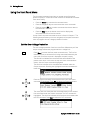
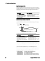
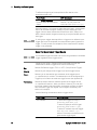
The Rear Panel – At a Glance
GPIB connector
1 2 3 4 5 6 7
+s +
-s
+s +
-s
+s +
-s
+s +
Output connector.
8-pin digital control
Includes +/−output and connector
Connector function is
+/− sense terminals.
user-configurable.
WARNING
Keysight N6700 User’s Guide
-s
USB connector LAN connector
10/100 Base-T
Left LED indicates
activity. Right LED
indicates link integrity.
SHOCK HAZARD The power cord provides a chassis ground through a
third conductor. Be certain that your power outlet is of the threeconductor type with the correct pin connected to earth ground.
11
1
Quick Reference
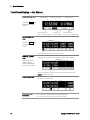
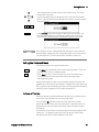
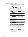
Front Panel Display – At a Glance
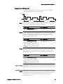
Single-channel view
Voltage
measurement
Bar indicates output
polarity is reversed
Current
measurement
Press the Meter key
to toggle between
views
Operating status
(CV = constant voltage)
Multiple-channel
view
Voltage and
current settings
Interface status
(IO = activity on interface)
Voltage and Current measurements
Press the Meter key
to toggle between
views
The highlighted channel is the active channel
Grouped-channel
view
Channels 2 through 4 are connected in parallel and have been
configured or grouped to act as a single, higher-power channel
Refer to Chapter 4,
under “SystemRelated Operations”
for more information
Grouped channels are addressed using the channel number of the
lowest channel in the group
Double-wide view
Interface status
indicators
12
Channel 2 is a double-wide power module that occupies two channel
locations in the mainframe
Err = an error has occurred (press Error key to display error message)
Lan = the LAN is connected and has been configured
IO = there is activity on one of the remote interfaces
Keysight N6700 User’s Guide
Quick Reference
Operating status
indicators
1
OFF = the output is off
CV = the output is in constant voltage mode
CC = the output is in constant current mode
CP+ = the output is limited (or disabled) by the positive power limit
CP– = the output is limited (or disabled) by the negative power limit
VL+/– = the output is in positive or negative voltage limit mode
CL+/– = the output is in positive or negative current limit mode
OV = the output is disabled by the over-voltage protection
OV– = the output is disabled by the negative over-voltage protection
OC = the output is disabled by the over-current protection
OT = the over-temperature protection has tripped
PF = the output is disabled by a power-fail condition
OSC = the output is disabled by the oscillation protection
INH = the output is disabled by an external inhibit signal
UNR = the output is unregulated
PROT = the output is disabled by a condition from a coupled channel
Front Panel Keys – At a Glance
System keys
Meter
Menu
Channel
Back
Help
Error
Meter returns the display to metering mode.
Menu accesses the command menu.
Channel selects or highlights a channel to control.
Back backs out of a menu without activating any changes.
Help accesses information about the displayed menu control.
Error displays any error messages in the error queue.
Navigation keys
The Arrow keys let you move around in the command menus.
The Select key lets you make a selection in the command menus.
It also lets you enter edit mode for numeric parameters.
Sel
Output keys
On/Off
Voltage
On/Off controls the selected output (or all outputs when All is lit).
This key is only active in Single- channel or Multiple-channel view.
Voltage lets you change the voltage setting of the selected channel.
Current lets you change the current setting of the selected channel.
Current
Number keys
7
8
9
4
5
6
1
2
3
0
.
+/-
Keysight N6700 User’s Guide
E
Enter
The 0 through 9 keys enter numbers. The (.) key is the decimal point.
The +/− key is only used to enter a minus sign.
The E key enters an exponent. Add the value to the right of the E.
The backspace key deletes digits as it backspaces over them.
The arrow keys increment or decrement the voltage or current
settings. They are also used to select letters in alphabetic entry fields.
The Enter key enters a value. If you exit a field without pressing the Enter
key, the value is ignored.
13
1
Quick Reference
Front Panel Menu Reference
NOTE
Menu commands that appear grayed-out on the front panel are either not
available for the power module, or are password protected.
Menu Command
Control Description
Output
Voltage
Programs voltage setting, limits, and ranges.
Current
Programs current setting, limits, and ranges.
Mode
Programs output priority mode on Models N678xA SMU.
Sequence
Advanced
Delay
Programs Turn-on /Turn off delay.
Couple
Couples output channels for output on/off synchronization.
Slew
Transient
States
14
Programs current slew rate on Models N678xA SMU.
Programs the power allocation function.
Pol
Lets you reverse the polarity of the output and sense terminals.
Resistance
Programs output resistance on Models N6781A, N6785A.
Bandwidth
Programs output voltage bandwidth on Models N678xA SMU.
Programs turn-on/turn-off impedance on Models N678xA SMU.
Range
Selects voltage and current measurement range.
Sweep
Specifies measurement points, time interval, and trigger offset.
Window
Selects measurement window: Rectangular, Hanning.
Input
Selects Auxiliary voltage measurements on Models N6781A, N6785A.
Control
Lets you abort a measurement in progress.
Mode
Selects voltage or current transient mode: Fixed, Step, List.
Step
Programs voltage and current step value. Enables step triggers.
List
Protect
Programs voltage slew rate.
Current
Power
Tmode
Measure
Voltage
Pace
Specifies Dwell or Trigger paced list.
Repeat
Specifies number of list repetitions, or specifies continuous list.
Terminate
Specifies list settings when the list terminates.
Config
Configures list step voltage, current, dwell, and trigger signals.
Reset
Aborts the list and resets all list parameters.
TrigSource
Specify the trigger source: Bus, Tran 1-4, Pin 1-7, Ext.
Control
Initiates, Triggers, or Aborts output triggers. Displays trigger state.
OVP
Configures over-voltage protection function.
OCP
Configures over-current protection function.
Inhibit
Configures the external inhibit signal: Off, Latching, Live
Coupling
Disables ALL output channels when a protection fault occurs.
Wdog
Configures the output watchdog timer.
Osc
Enables/disables oscillation protection on Models N678xA SMU.
Clear
Clears output protection. Displays output state.
Reset
Resets the instrument to its reset (*RST) state.
SaveRecall
Saves or recalls an instrument state.
PowerOn
Selects the power-on state: *RST, RCL0.
Keysight N6700 User’s Guide
Quick Reference
Menu Command
System
IO
Control Description
LAN
USB
ActiveSettings
Displays the LAN interface settings that are presently active.
Config
IP
Configures the IP addressing of the instrument.
Name
Configures the Dynamic DNS and NetBIOS naming service.
Domain
Configures the Domain Name.
DNS
Configures the DNS server.
TCP
Configures the TCP keepalive function.
Reset
Resets the LAN interface settings to the factory-shipped state.
Status
Displays status, speed, packets received, and packets sent.
Identification
USB connect string - the instrument’s unique USB identifier.
GPIB
DigPort
Selects the GPIB address.
Pins<1>
Function
Specifies the pin function: DigIn, DigIO, TrigIn, TrigOut, FaultOut.
Pins<2>
Function
Specifies the pin function: DigIn, DigIO, TrigIn, TrigOut.
Pins<3>
Function
Specifies the pin function: DigIn, DigIO, TrigIn, TrigOut, InhibitIn.
Pins<4-7>
Function
Specifies the pin function: DigIn, DigIO, TrigIn, TrigOut, OnC, OffC.
Pins<1-7>
Polarity
Specifies the pin polarity: Positive, Negative
Data
Sends/reads data from the digital I/O port
Groups
Preferences
Admin
1
Defines groups of output channels that are connected in parallel.
Display
Contrast
Configures the display contrast.
Saver
Configures the screen saver and wake-on I/O timer.
View
Selects 1-channel or 4-channel view at turn-on
Keys
Enables/disables key clicks and configures the On/Off key.
Lock
Locks front panel keys. Enter a password to unlock the front panel.
Login/Logout
Enter a password to access the admin functions.
Cal
Volt
Curr
Misc
Vprog
Calibrates High and Low voltage ranges.
Vlim
Calibrates voltage limit High and Low ranges
Vmeas
Calibrates High, Low, and Aux voltage measurement ranges.
Iprog
Calibrates High and Low current ranges.
Ilim
Calibrates current limit.
Imeas
Calibrates High and Low current measurement ranges.
CMRR
Calibrates common mode rejection ratio.
Dprog
Calibrates the downprogrammer.
Ipeak
Calibrates I peak.
Resistance Calibrates output resistance High and Low ranges.
About
Date
Saves the calibration date for each channel.
Save
Saves the calibration data.
LAN
Enables/disables the LAN interface and the built-in Web server.
USB
Enables/disables the USB interface.
Nvram
Resets all non-volatile RAM settings to their factory defaults.
Password
Changes the password for the admin functions.
Frame
Displays model, serial number, and firmware revisions.
Module
Displays model, serial number, options, voltage, current, power.
Keysight N6700 User’s Guide
15
1
Quick Reference
SCPI Command Summary
Subsystem Commands
NOTE
Some [optional] commands have been included for clarity. All settings commands
have a corresponding query. Not all commands apply to all models.
SCPI Command
Description
ABORt
:ACQuire (@chanlist)
:ELOG (@chanlist)
:TRANsient (@chanlist)
Resets the measurement trigger system to the Idle state
Stops the external data log
Resets the transient trigger system to the Idle state
CALibrate
:CURRent
[:LEVel] <NRf>, (@channel)
:LIMit
:NEGative <NRf>, (@channel)
:POSitive <NRf>, (@channel)
:MEASure <NRf>, (@channel)
:PEAK (@channel)
:DATA <NRf>
:DATE <”date”>, (@channel)
:DPRog (@channel)
:LEVel P1 | P2 | P3
:PASSword <NRf>
:RESistance 20| 6, (@channel)
:SAVE
:STATE <Bool> [,<NRf>]
:VOLTage
[:LEVel] <NRf>, (@channel)
:CMRR (@channel)
:LIMit
:POSitive <NRf>, (@channel)
:MEASure <NRf>, (@channel)
:AUXiliary (@channel)
DISPlay
[:WINDow]
:CHANnel <channel>
:VIEW METER1 | METER4
FETCh
[:SCALar]
:CURRent
[:DC]? (@chanlist)
:ACDC? (@chanlist)
:HIGH? (@chanlist)
:LOW? (@chanlist)
:MAXimum? (@chanlist)
:MINimum? (@chanlist)
:POWer
[:DC]? (@chanlist)
:VOLTage
[:DC]? (@chanlist)
:ACDC? (@chanlist)
:HIGH? (@chanlist)
:LOW? (@chanlist)
:MAXimum? (@chanlist)
:MINimum? (@chanlist)
16
Calibrates the output current programming
Calibrates the negative current limit (only on N6783A)
Calibrates the positive current limit (only on N678xA SMU)
Calibrates the current measurement
Calibrates the peak current limit (only on N675xA, N676xA)
Enters the calibration value
Sets the calibration date
Calibrates the current downprogrammer
Advances to the next calibration step
Sets the numeric calibration password
Calibrates the output resistance (only on N6781A, N6785A)
Saves the new cal constants in non-volatile memory
Enables/disables calibration mode
Calibrates the output voltage programming
Calibrates common mode rejection ratio (only N675xA, N676xA)
Calibrates the positive voltage limit (only on N678xA SMU)
Calibrates the voltage measurement
Calibrates the auxiliary voltage measurement (only on N6781A, N6785A)
Selects the channel in 1-channel meter view
Selects 1-channel or 4-channel meter view
(Fetch commands only on N676xA, N678xA SMU and Option 054)
Returns the average current
Returns the total rms current (AC + DC)
Returns the high level of a current pulse
Returns the low level of a current pulse
Returns the maximum current
Returns the minimum current
Returns the average output power
Returns the average voltage
Returns the total rms voltage (AC + DC)
Returns the high level of a voltage pulse
Returns the low level of a voltage pulse
Returns the maximum voltage
Returns the minimum voltage
Keysight N6700 User’s Guide
Quick Reference
SCPI Command
Description
FETCh (continued)
:ARRay
:CURRent [:DC]? (@chanlist)
:POWer [:DC]? (@chanlist)
:VOLTage [:DC]? (@chanlist)
:ELOG <NR1>, (@chanlist)
Returns the instantaneous output current
Returns the instantaneous output power
Returns the instantaneous output voltage
Returns the most recent external data log records
FORMat
[:DATA] ASCII | REAL
:BORDer NORMal | SWAPped
Returns data as ASCII or binary
Sets the byte order of the external data log data
INITiate
[:IMMediate]
:ACQuire (@chanlist)
:ELOG (@chanlist)
:TRANsient (@chanlist)
:CONTinuous
:TRANsient <Bool>, (@chanlist)
MEASure
[:SCALar]
:CURRent
[:DC]? (@chanlist)
:ACDC? (@chanlist)
:HIGH? (@chanlist)
:LOW? (@chanlist)
:MAXimum? (@chanlist)
:MINimum? (@chanlist)
:POWer
[:DC]? (@chanlist)
:VOLTage
[:DC]? (@chanlist)
:ACDC? (@chanlist)
:HIGH? (@chanlist)
:LOW? (@chanlist)
:MAXimum? (@chanlist)
:MINimum? (@chanlist)
:ARRay
:CURRent [:DC]? (@chanlist)
:POWer [:DC]? (@chanlist)
:VOLTage [:DC]? (@chanlist)
OUTPut
[:STATe] <Bool> [,NORelay], (@chanlist)
:COUPle
[:STATe] <Bool>
:CHANNel [<NR1> {,<NR1>}]
:DOFFset <NRf>
:MAX
:DOFFset?
:DELay
:FALL <NRf+>, (@chanlist)
:RISE <NRf+>, (@chanlist)
:PMODe VOLTage | CURRent, (@chanlist)
:TMODe HIGHZ | LOWZ, (@chanlist)
:INHibit
:MODE LATChing | LIVE | OFF
:PON
:STATe RST | RCL0
Keysight N6700 User’s Guide
1
(Acquire command only on N676xA, N678xA SMU and Option 054)
Enables the measurement system to receive triggers
Enables external data log measurements
Enables the output transient system to receive triggers
Enables/disables continuous transient triggers
Takes a measurement; returns the average current
Takes a measurement; returns the total rms current (AC + DC)
Takes a measurement; returns the high level of a current pulse
Takes a measurement; returns the low level of a current pulse
Takes a measurement, returns the maximum current
Takes a measurement, returns the minimum current
Takes a measurement, returns the average output power
Takes a measurement; returns the average voltage
Takes a measurement; returns the total rms voltage (AC + DC)
Takes a measurement; returns the high level of a voltage pulse
Takes a measurement; returns the low level of a voltage pulse
Takes a measurement, returns the maximum voltage
Takes a measurement, returns the minimum voltage
(Array commands only on N676xA, N678xA SMU and Option 054)
Takes a measurement; returns the instantaneous output current
Takes a measurement; returns the instantaneous output power
Takes a measurement; returns the instantaneous output voltage
Enables/disables the specified output channel(s)
Enables/disables channel coupling for output synchronization
Selects which channels are coupled
Specifies a maximum delay offset to synchronize output changes
Returns the maximum delay offset required for a mainframe
Sets the output turn-off sequence delay
Sets the output turn-on sequence delay
Sets the mode for turn on/off transitions (N6761A, N6762A)
Specifies the turn-on/turn-off impedance (only on N678xA SMU)
Sets the remote inhibit input
Programs the power-on state
17
1
Quick Reference
SCPI Command
:PROTection
:CLEar (@chanlist)
:COUPle <Bool>
:DELay <NRf+>, (@chanlist)
:OSCillation <Bool>, (@chanlist)
:WDOG
[:STATe] <Bool>
:DELay <NRf+>
:RELay
:POLarity NORMal | REVerse, (@chanlist)
SENSe
:CURRent
:CCOMpensate <Bool>, (@chanlist)
[:DC]:RANGe
[:UPPer] <NRf+>, (@chanlist)
:AUTO <Bool>, (@chanlist)
:ELOG
:CURRent
[:DC]:RANGe
[:UPPer] <NRf+>, (@chanlist)
:AUTO <Bool>, (@chanlist)
:FUNCtion
:CURRent <Bool>, (@chanlist)
:MINMax <Bool>, (@chanlist)
:VOLTage <Bool>, (@chanlist)
:MINMax <Bool>, (@chanlist)
:PERiod <NR1>, (@chanlist)
:VOLTage
[:DC]:RANGe
[:UPPer] <NRf+>, (@chanlist)
:AUTO <Bool>, (@chanlist)
:FUNCtion “VOLTage” | ”CURRent” | “NONE”, (@chanlist)
:CURRent <Bool>, (@chanlist)
:VOLTage <Bool>, (@chanlist)
:INPut MAIN | AUXiliary, (@chanlist)
:SWEep
:OFFSet
:POINts <NRf+>, (@chanlist)
:POINts <NRf+>, (@chanlist)
:TINTerval <NRf+>, (@chanlist)
:RESolution RES20 | RES40, (@chanlist)
:VOLTage
[:DC]:RANGe
[:UPPer] <NRf+>, (@chanlist)
:AUTO <Bool>, (@chanlist)
:WINDow
[:TYPE] HANNing | RECTangular, (@chanlist)
[SOURce:]
CURRent
[:LEVel]
[:IMMediate][:AMPLitude] <NRf+>, (@chanlist)
:TRIGgered [:AMPLitude] <NRf+>, (@chanlist)
:LIMit
[:POSitive]
[:IMMediate][:AMPLitude] <NRf+>, (@chanlist)
:COUPle <Bool>, (@chanlist)
:NEGative
[:IMMediate][:AMPLitude] <NRf+>, (@chanlist)
18
Description
Resets latched protection
Enables/disables channel coupling for protection faults
Sets over-current protection programming delay
Enables/disables output oscillation protection (N678xA SMU)
Enables/disables the I/O watchdog timer
Sets the watchdog timer delay
Sets the output relay polarity (Option 760)
Enables/disables the capacitive current compensation
Selects the current measurement range
Enables/disables measurement autoranging (N6781A, N6782A, N6785A,
N6786A)
Sets the external data log current range
Enables/disables measurement autoranging (N6781A, N6782A, N6785A,
N6786A)
Enables/disables external current data logging
Enables/disables external min/max current data logging
Enables/disables external voltage data logging
Enables/disables external min/max voltage data logging
Sets the integration time of the external data logging
Sets the external data log voltage range
Enables/disables measurement autoranging (N6781A, N6782A)
Selects the measurement function (for backward compatibility)
Enables/disables current measurements (replaces FUNCtion)
Enables/disables voltage measurements (replaces FUNCtion)
Selects the voltage measurement input (only on N6781A, N6785A)
(Sweep commands only on N676xA, N678xA SMU and Option 054)
Defines the trigger offset in the measurement sweep
Defines the number of data points in the measurement
Sets the measurement sample interval
Sets the measurement resolution
Selects the voltage measurement range
Enables/disables measurement autoranging (N6781A N6782A)
Selects measurement window (N676xA, N678xA SMU, Option 054)
Sets the output current
Sets the triggered output current
Sets the positive current limit (only on N678xA SMU, N6783A)
Sets the current limit tracking state (only on N678xA SMU)
Sets the negative current limit (only on N678xA SMU, N6783A-BAT)
Keysight N6700 User’s Guide
Quick Reference
SCPI Command
[SOURce:]CURRent (continued)
:MODE FIXed | STEP | LIST, (@chanlist)
:PROTection
:DELay
[:TIME] <NRf+>, (@chanlist)
:STARt SCHange | CCTRans, (@chanlist)
:STATe <Bool>, (@chanlist)
:RANGe <NRf+>, (@chanlist)
:SLEW
[:IMMediate] <NRf+> | INFinity, (@chanlist)
:MAXimum <Bool>, (@chanlist)
DIGital
:INPut:DATA?
:OUTPut:DATA <NRf>
:PIN<1-7>
:FUNCtion DIO | DINPut | TOUTput | TINPut | FAULt
| INHibit | ONCouple | OFFCouple
:POLarity POSitive | NEGative
:TOUTput
:BUS[:ENABle] <Bool>
Description
Sets the current trigger mode
Sets the over-current protection programming delay
Sets the over-current protection programming mode
Enables/disables over-current protection on the selected output
Sets the output current range
Sets the output current slew rate (only N678xA SMU)
Enables/disables the maximum slew rate override (N678xA SMU)
Reads the state of the digital port pins
Sets the digital port
Sets the selected pin’s function
Sets the selected pin’s polarity
Enables/disables BUS-generated triggers on digital pins
FUNCtion CURRent | VOLTage, (@chanlist)
Specifies current priority or voltage priority mode (N678xA SMU)
LIST
:COUNt <NRf+> | INFinity, (@chanlist)
:CURRent
[:LEVel] <NRf> {,<NRf>}, (@chanlist)
:POINts? (@chanlist)
:DWELl <NRf> {,<NRf>}, (@chanlist)
:POINts? (@chanlist)
:STEP ONCE | AUTO, (@chanlist)
:TERMinate
:LAST <Bool>, (@chanlist)
:TOUTput
:BOSTep
[:DATA] <Bool> {,<Bool>}, (@chanlist)
:POINts? (@chanlist)
:EOSTep
[:DATA] <Bool> {,<Bool>}, (@chanlist)
:POINts? (@chanlist)
:VOLTage
[:LEVel] <NRf> {,<NRf>}, (@chanlist)
:POINts? (@chanlist)
(List commands only on N676xA, N678xA SMU and Option 054)
Sets the list repeat count
Sets the current list
Returns the number of current list points
Sets the list of dwell times
Returns the number of dwell list points
Specifies how the list responds to triggers
Sets the list termination mode
Generate triggers at the Beginning Of Step
Returns the number of beginning of step list points
Generate triggers at the End Of Step
Returns the number of end of step list points
Sets the voltage list
Returns the number of voltage level points
POWer
:LIMit <NRf+>, (@chanlist)
Sets the power limit on output channels
RESistance
[:LEVel][:IMMediate][:AMPLitude] <NRf+>, (@chanlist)
:STATe <Bool>, (@chanlist)
Sets the output resistance (only on N6781A, N6785A)
Enables/disables output resistance programming (only N6781A, N6785A)
STEP
:TOUTput <Bool>, (@chanlist)
Generate a trigger output on the voltage or current step transient
VOLTage
[:LEVel]
[:IMMediate][:AMPLitude] <NRf+>, (@chanlist)
:TRIGgered [:AMPLitude] <NRf+>, (@chanlist)
:BWIDth LOW | HIGH1 | HIGH2 | HIGH3, (@chanlist)
Sets the output voltage
Sets the triggered output voltage
Sets the voltage bandwidth (only on N678xA SMU)
Keysight N6700 User’s Guide
1
19
1
Quick Reference
SCPI Command
[SOURce:]VOLTage (continued)
:LIMit
[:POSitive]
[:IMMediate][:AMPLitude] <NRf+>, (@chanlist)
:COUPle <Bool>, (@chanlist)
:NEGative
[:IMMediate][:AMPLitude] <NRf+>, (@chanlist)
:MODE FIXed | STEP | LIST, (@chanlist)
:PROTection
[:LEVel] <NRf+>, (@chanlist)
:DELay[:TIME] <NRf+>, (@chanlist)
:REMote
[:POSitive][:LEVel] <NRf+>, (@chanlist)
:NEGative[:LEVel] <NRf+>, (@chanlist)
:TRACking
[:STATe] <Bool>, (@chanlist)
:OFFSet <NRf+>, (@chanlist)
:RANGe <NRf+>, (@chanlist)
:SLEW
[:IMMediate] <NRf+> | INFinity, (@chanlist)
:MAXimum <Bool>, (@chanlist)
STATus
:OPERation
[:EVENt]? (@chanlist)
:CONDition? (@chanlist)
:ENABle <NRf>, (@chanlist)
:NTRansition <NRf>, (@chanlist)
:PTRansition <NRf>, (@chanlist)
:PRESet
:QUEStionable
[:EVENt]? (@chanlist)
:CONDition? (@chanlist)
:ENABle <NRf>, (@chanlist)
:NTRansition <NRf>, (@chanlist)
:PTRansition <NRf>, (@chanlist)
SYSTem
:CHANnel
[:COUNt]?
:MODel? (@chanlist)
:OPTion? (@chanlist)
:SERial? (@chanlist)
:COMMunicate
:RLSTate LOCal | REMote | RWLock
:TCPip:CONTrol?
:ERRor?
:GROup
:CATalog?
:DEFine (@chanlist)
:DELete <channel>
:ALL
:PASSword:FPANel:RESet
:REBoot
:VERSion?
TRIGger
:ACQuire
[:IMMediate] (@chanlist)
:CURRent
[:LEVel] <NRf>, (@chanlist)
:SLOPe POSitive | NEGative, (@chanlist)
20
Description
Sets the positive voltage limit (only on N678xA SMU)
Sets the voltage limit tracking state (only on N6784A)
Sets the negative voltage limit (only on N6784A)
Sets the voltage trigger mode
Sets the over-voltage protection level
Sets the over-voltage protection delay (only on N6783A)
Sets the positive remote OV protection level (only on N678xA SMU)
Sets the negative remote OV protection level (only on N6784A)
(Tracking commands only on Option J01)
Enables/disables tracking OVP
Sets the tracking OVP offset
Sets the output voltage range
Sets the output voltage slew rate
Enables/disables the maximum slew rate override
Returns the value of the operation event register
Returns the value of the operation condition register
Enables specific bits in the Event register
Sets the Negative transition filter
Sets the Positive transition filter
Presets all enable and transition registers to power-on
Returns the value of the questionable event register
Returns the value of the questionable condition register
Enables specific bits in the Event register
Sets the Negative transition filter
Sets the Positive transition filter
Returns the number of output channels in a mainframe
Returns the model number of the selected channel
Returns the option installed in the selected channel
Returns the serial number of the selected channel
Specifies the Remote/Local state of the instrument
Returns the control connection port number
Returns the error number and error string
(Group commands do NOT apply to N678xA SMU)
Returns the groups that have been defined
Group multiple channels to create a single output
Removes the specified channel from a group
Ungroups all channels
Resets the front panel lock password to zero
Returns the unit to its power-on state
Returns the SCPI version number
(Acquire commands only on N676xA, N678xA SMU and Option 054)
Triggers the measurement immediately
Sets the current trigger level
Sets the current trigger slope
Keysight N6700 User’s Guide
Quick Reference
SCPI Command
TRIGger (continued)
:SOURce BUS | CURRent<1-4> | EXTernal | PIN<1-7>
|TRANsient<1-4> | VOLTage<1-4>, (@chanlist)
:TOUTput[:ENABle] <Bool>, (@chanlist)
:VOLTage
[:LEVel] <NRf>, (@chanlist)
:SLOPe POSitive | NEGative, (@chanlist)
:ELOG
[:IMMediate] (@chanlist)
:SOURce BUS|EXTernal|IMMediate|PIN<1-7>, (@chanlist)
:TRANsient
[:IMMediate] (@chanlist)
:SOURce BUS | EXTernal | IMMediate | PIN<1-7>
| TRANsient<1-4>, (@chanlist)
1
Description
Sets the measurement trigger source
Enables measurement triggers to be sent to a digital port pin
Sets the voltage trigger level
Sets the voltage trigger slope
Triggers the external data log immediately
Sets the external data log trigger source
Triggers the output immediately
Sets the output trigger source
Common Commands
Command
Description
Command
Description
*CLS
*ESE <NRf>
*ESR?
*IDN?
*LRN
*OPC
*OPT?
*RCL <NRf>
Clear status
Standard event status enable
Return event status register
Return instrument identification
Returns a sequence of SCPI commands
Enable "operation complete" bit in ESR
Return option number
Recalls a saved instrument state
*RDT?
*RST
*SAV <NRf>
*SRE <NRf>
*STB?
*TRG
*TST?
*WAI
Return output channel descriptions
Reset
Saves an instrument state
Set service request enable register
Return status byte
Trigger
Performs self-test, then returns result
Waits until all device commands are done
Keysight N6700 User’s Guide
21
1
Quick Reference
*RST Settings
CAL:STAT
CURR
CURR:LIM
CURR:LIM:COUP
CURR:LIM:NEG
CURR:MODE
CURR:PROT:DEL
CURR:PROT:DEL:STAR
CURR:PROT:STAT
CURR:RANG
CURR:SLEW
CURR:SLEW:MAX
CURR:TRIG
DIG:OUTP:DATA
DISP:VIEW
INIT:CONT:TRAN
LIST:COUN
LIST:CURR
LIST:DWEL
LIST:STEP
LIST:TERM:LAST
LIST:TOUT:BOST
LIST:TOUT:EOST
LIST:VOLT
OUTP
OUTP:COUP
OUTP:DEL:FALL
OUTP:DEL:RISE
OUTP:PMOD
OUTP:TMOD
OUTP:PROT:COUP
OUTP:PROT:DEL
OUTP:PROT:OSC
OUTP:PROT:WDOG
OUTP:REL:POL
POW:LIM
RES
RES:STAT
SENS:CURR:CCOM
SENS:CURR:RANG
SENS:CURR:RANG:AUTO
22
OFF
0.08 or MIN
MAX
ON
MIN
FIX
0.02
SCH
OFF
MAX
9.9E+37
ON
MIN
0
METER1
OFF
1
MIN
0.001
AUTO
OFF
OFF
OFF
MIN
OFF
OFF
0
0
VOLT
LOWZ
OFF
0.02
ON
OFF
NORM
MAX
0
OFF
ON
MAX
OFF
SENS:ELOG:CURR:RANG:AUTO
SENS:ELOG:FUNC:CURR
SENS:ELOG:FUNC:CURR:MINM
SENS:ELOG:FUNC:VOLT
SENS:ELOG:FUNC:VOLT:MINM
SENS:ELOG:PER
SENS:ELOG:VOLT:RANG:AUTO
SENS:FUNC
SENS:FUNC:CURR
SENS:FUNC:VOLT
SENS:FUNC:VOLT:INP
SENS:SWE:POIN
SENS:SWE:OFFS:POIN
SENS:SWE:TINT
SENS:SWE:TINT:RES
SENS:VOLT:RANG
SENS:VOLT:RANG:AUTO
SENS:WIND
STEP:TOUT
TRIG:ACQ:CURR
TRIG:ACQ:CURR:SLOP
TRIG:ACQ:SOUR
TRIG:ACQ:TOUT
TRIG:ACQ:VOLT
TRIG:ACQ:VOLT:SLOP
TRIG:ELOG:SOUR
TRIG:TRAN:SOUR
VOLT
VOLT:BWID
VOLT:LIM
VOLT:LIM:COUP
VOLT:LIM:NEG
VOLT:MODE
VOLT:PROT:DEL
VOLT:PROT:REM
VOLT:PROT:REM:NEG
VOLT:RANG
VOLT:SLEW
VOLT:SLEW:MAX
[SOUR:]VOLT:TRIG
OFF
ON
OFF
OFF
OFF
0.1
OFF
“VOLT”
OFF
ON
MAIN
1024 or 4883
0
20.48E−6
RES20
MAX
OFF
RECT
FALSE
MIN
POS
BUS
OFF
MIN
POS
BUS
BUS
MIN
LOW
MAX
ON
MIN
FIX
0
MAX
MIN
MAX
9.9E+37
ON
MIN
Keysight N6700 User’s Guide
2
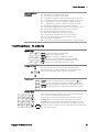
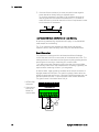
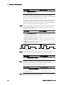
Installation
General Information ....................................................................... 24
Inspecting the Unit ......................................................................... 25
Installing the Unit ........................................................................... 26
Connecting the Line Cord .............................................................. 30
Connecting the Outputs ................................................................. 31
Remote Sense Connections ........................................................... 36
Parallel Connections ...................................................................... 38
Series Connections......................................................................... 40
Additional Load Considerations ..................................................... 42
Connecting the Auxiliary Voltage Measurement Input ................. 44
This chapter describes how to install your power system. It discusses
rack mounting and line cord connections.
This chapter also discusses how to connect your load to the output
terminals. It discusses what you need to know about wire sizes and how
to compensate for voltage drops in the load leads. It describes various
loads configurations and how to connect the output terminals in series
and parallel.
Before installing the instrument, check the list under “Items Supplied”
and verify that you have received these items with your instrument. If
anything is missing, please contact your nearest Keysight Sales and
Support Office.
2
Installation
General Information
Models
Keysight Model
Description
N6700B / N6701A / N6702A
400 W / 600 W / 1200W MPS Mainframe - without power modules
N6710B / N6711A / N6712A
Build-to-order Modular Power System – mainframe with installed power modules
N6731B / N6741B
50 W / 100 W 5 V DC Power Module
N6732B / N6742B
50 W / 100 W 8 V DC Power Module
N6733B / N6743B / N6773A
50 W / 100 W / 300 W 20 V DC Power Module
N6734B / N6744B / N6774A
50 W / 100 W / 300 W 35 V DC Power Module
N6735B / N6745B / N6775A
50 W / 100 W / 300 W 60 V DC Power Module
N6736B / N6746B / N6776A, N6777A
50 W / 100 W / 300 W 100 V DC Power Module
N6751A / N6752A
50 W / 100 W High-Performance Autoranging DC Power Module
N6753A, N6754A / N6755A , N6756A
300 W / 500 W High-Performance Autoranging DC Power Module
N6761A / N6762A
50 W / 100 W Precision DC Power Module
N6763A, N6764A / N6765A, N6766A
300 W / 500 W Precision DC Power Module
N6781A, N6782A, N6784A
20 W Source/Measure Unit (SMU)
N6785A, N6786A
80 W Source/Measure Unit (SMU)
N6783A-MFG / N6783A-BAT
18 W / 24 W Application-Specific DC Power Module
Options
Mainframe
Options
Description
0L1
English Manual Set. Contains User’s Guide and Service Guide. Also available as part number 5969-2939.
908
Rack Mount Kit. For mounting in a 19-inch EIA rack cabinet. Also available as Model N6709A.
FLR
Filler module. For mainframes with less than four power modules. Also available as Model N6708A.
Power Module Options
054
High-Speed Test Extensions. Includes digitized output measurements and output list capability.
Available for Models N673xB,- 4xB,-5xA, -7xA. Included with Models N676xA, N678xA SMU, and N6783A.
760 NOTE 1
Output disconnect/polarity reversal. Disconnects the + and – output and sense terminals. Switches the
+ and – output and sense polarities. Not available on N6741B, N6751A, N6752A, N676xA, or N678xA.SMU.
761 NOTE 1
Output disconnect. Disconnects + and – output and sense terminals. Available for all power modules.
UK6
Commercial calibration with test results data
1A7
ISO 17025 calibration certificate
2UA
200 microampere measurement range with output disconnect relays. Only on Models N6761A, N6762A.
J01
Tracking overvoltage protection function. Only available on Models N6752A, N6754A, and N6762A when
installed in an N6700B, N6701A, or N6702A mainframe.
1
24
A small AC network is always present across the output terminals.
Keysight N6700 User’s Guide
Installation
2
Items Supplied
Mainframe Items
Description
Part Number
Power Cord
A power cord suitable for your location.
Call Keysight Sales & Support Office
Ferrite Core for N6700B
Installs on power cord to reduce common mode currents.
Keysight 9170-2131
Digital Connector plug
8-pin connector for connecting signal lines to the digital port.
Keysight 1253-6408
Phoenix Contact MC 1,5/8-ST-3,5
Product Reference CD-ROM
Includes drivers and documentation.
Keysight 5969-2914
Automation-Ready CD-ROM
Contains Keysight IO Libraries Suite.
Keysight E2094N
Quick Reference Guide
Contains quick reference information.
Keysight 5969-2950
T-10 Torx tool
Torx tool for installing or removing power modules.
Keysight 8710-2416
8 A Output Connector plug
One 8 A, 8-pin connector plug for connecting power and sense
leads. Only used in N678xA SMU.
Keysight 1253-6408
Phoenix Contact MC 1,5/8-ST-3,5
12 A Output Connector plug
One 12 A, 4-pin connector plug for connecting power and sense
leads. Used in all except N6731B, N6741B, N6753A-N6756A,
N6763A-N6766A, N6773A, N678xA SMU.
Keysight 1253-5826
Phoenix Contact MSTB 2,5/4-STF
20 A Output Connector plug
One 20 A, 4-pin connector plug for connecting power and sense
leads. Only used in N6731B, N6741B, N6754A, N6756A,
N6764A, N6766A, N6773A.
Keysight 1253-6211
Phoenix Contact PC 4/4-ST-7,62
50 A Output Connector plug
One 50 A, 2-pin connector plug for connecting power leads. Only
used in N6753A, N6755A, N6763A, N6765A.
Keysight 1253-7187
Molex 39422-0002
AUX Measurement connector
plug
A 2-pin connector plug for connecting the auxiliary measurement
inputs. Only used in N6781A and N6785A.
Keysight 1253-8485
Phoenix Contact FMC 1,5/2-ST-3,5
Small Sense Jumpers
Two small jumpers for local sensing at the output connector.
Used in all except N6731B, N6741B, N6753A-N6756A, N6763AN6766A, N6773A, N678xA SMU.
Keysight 8120-8821
Phoenix Contact EPB 2-5(1733169)
Large Sense Jumpers
Two large jumpers for local sensing at the output connector. Only
used in N6731B, N6741B, N6754A, N6756A, N6764A, N6766A,
N6773A.
Keysight 0360-2935
Phoenix Contact 3118151
Sense Connector
A 4-pin connector for connecting sense leads. Wires (p/n 51858847) are used for local sensing. Only used in N6753A, N6755A,
N6763A, N6765A.
Keysight 1253-5830
Phoenix Contact MC 1,5/4-ST-3,5
Module Cal. Certificate
A certificate of calibration referenced to the serial number.
N/A
Power Module Items
Inspecting the Unit
When you receive your power system, inspect it for any obvious damage
that may have occurred during shipment. If there is damage, notify the
shipping carrier and nearest Keysight Sales and Support Office
immediately. Refer to www.keysight.com/find/assist.
Until you have checked out the power system, save the shipping carton
and packing materials in case the unit has to be returned. Check the list
under “Items Supplied” and verify that you have received these items
with your instrument. If anything is missing, please contact your nearest
Keysight Sales and Support Office.
Keysight N6700 User’s Guide
25
2
Installation
Installing the Unit
Safety Considerations
This power system is a Safety Class 1 instrument, which means it has a
protective earth terminal. That terminal must be connected to earth
ground through a power source equipped with a ground receptacle.
Refer to the Safety Summary page at the beginning of this guide for
general safety information. Before installation or operation, check the
power system and review this guide for safety warnings and instructions.
Safety warnings for specific procedures are located at appropriate places
throughout this Guide.
Environment
WARNING
Do not operate the instrument in the presence of flammable gasses or
fumes
The environmental conditions of the instrument are documented in
Appendix A. Basically, the instrument should only be operated indoors in
a controlled environment.
The dimensions of your instrument as well as an outline diagram are
given in Appendix A. A fan cools the power system by drawing air
through the sides and exhausting it out the side and back. The
instrument must be installed in a location that allows sufficient space at
the sides and back of the unit for adequate air circulation.
Cleaning
WARNING
SHOCK HAZARD To prevent electric shock, unplug the unit before
cleaning.
Use a dry cloth or one slightly dampened with water to clean the
external case parts. Do not use detergent or chemical solvents. Do not
attempt to clean internally.
Power Module Channel Assignment
The slot location of a power module in the mainframe determines the
channel assignment of the module. When viewed from the rear, the
module next to the GPIB connector is always output channel one.
Numbering continues sequentially to the left, from 1 up to 4.
Double-wide power modules are assigned the number of the lowest
numbered slot in which is installed. For example, if a double-wide module
is installed in slots 3 and 4, it is assigned channel number 3.
Grouped power modules, those that are connected in parallel and have
been configured or grouped to act as a single higher-power channel, are
assigned the channel number of the lowest numbered slot of the group.
26
Keysight N6700 User’s Guide
Installation
2
Power Module Installation
NOTE
CAUTION
The information in this section applies if you have purchased an N6700
mainframe without the power modules installed, or if you are adding a power
module to the mainframe.
Turn the mainframe off and disconnect the power cord before installing or
removing power modules. Observe all standard electrostatic discharge
precautions before handling electronic components.
Modules must be installed next to one another, starting with slot 1. Do not leave
any empty slots between modules, otherwise the power system will not operate.
Any remaining unused slots must have a filler module installed to ensure proper
cooling. Do not install filler modules between power modules.
Tools required: T10 Torx driver;
Small flat-blade screwdriver
Firmware Note: Newer power modules can only be installed in N6700
mainframes with the latest firmware. Refer to the “Updates” section in
the front of this manual for more information. If your mainframe has the
latest firmware version, install the power module. If not, download and
install the latest version firmware from the web.
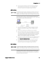
Step 1. Remove the blower cover. Remove the screws from the top and sides of
the blower cover. Tilt the cover up and slide it out.
Step 2. To install a power module, align the module over the pins and push it
down onto the mainframe connector.
Keysight N6700 User’s Guide
27
2
Installation
Step 3. Use a T10 Torx driver and install the screws at each end of the power
module. Because the RFI strips apply upward pressure, continue pushing
down on the module until the screws are tight.
Step 4. Replace the blower cover when finished. Carefully fit the spring clips
under the lip of the power modules.
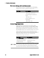
Rack Installation
CAUTION
You cannot use support rails for rack mounting your instrument.
Support rails would block the airflow needed for cooling.
Use Rack Mount kit (Option 908) to rack mount your instrument.
The Rack Mount Kit is also available by ordering part number N6709A.
Keysight N6700 MPS mainframes can be mounted in a 19-inch EIA rack
cabinet. They are designed to fit in one rack-unit (1U) of space. Do not
block the air intake and exhaust at the sides of the unit, or the exhaust at
the rear of the unit.
Tools required:
Phillips driver, T22 Torx driver, T10 Torx driver
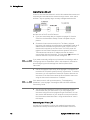
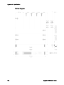
Step 1. Install eight clip-nuts on the rack frame (2 in each corner) where your
instrument will be located.
4
3
1
6
2b
2d
2c
5
28
2a
1
Keysight N6700 User’s Guide
Installation
2
Step 2. Install the two front ears and the two rear extender supports on the
instrument as shown in the figure. Use six M3 x 8mm screws (a) for the
front ears and four M3 x 6mm screws (b) for the extender supports. If the
standard extender supports are either too short or too long, use the
longer supports (c). Cut the supports if required (d).
Step 3. Install the two rear ears on the back of the instrument rack as shown in
the figure. Use four plain 10-32 screws to install the rear ears.
Step 4. Slide the instrument into the rack, making sure that the rear extender
supports are aligned inside the rear ears.
Step 5. Attach the front ears to the front of the instrument rack using the four
dress 10-32 screws provided.
Step 6. This is optional. Insert a plain 10-32 screw through the slot of the rear
ear and extender support. Attach it with a clip-nut. Note that this will
prevent the unit from being slid out of the front of the rack.
Bench Installation
CAUTION
Do not block the air intake and exhaust at the sides, or the exhaust at
the rear of the unit. Refer to the outline diagram in Appendix A.
Minimum clearances for bench operation are 2 inches (51 mm) along the
sides and back.
400 Hz Operation
Redundant Ground Requirement
At 400 Hz AC input operation, the leakage current of the unit exceeds
3.5 mA. This requires the installation of a permanent, redundant ground
from the instrument chassis to earth ground. This ensures that ground
will always be connected and that any leakage current will be diverted to
ground. Refer to the Service Guide for installation instructions.
Power Factor
Refer to Appendix A for power factor statistics at 400 Hz operation.
Keysight N6700 User’s Guide
29
2
Installation
Connecting the Line Cord
WARNING
FIRE HAZARD Use only the power cord that was supplied with your
instrument. Using other types of power cords may cause overheating of
the power cord, resulting in fire.
SHOCK HAZARD The power cord provides a chassis ground through a
third conductor. Be certain that your power outlet is of the threeconductor type with the correct pin connected to earth ground.
Connect the power cord to the IEC 320 connector on the rear of the unit.
If the wrong power cord was shipped with your unit, contact your
nearest Keysight Sales and Support Office.
The AC input on the back of your unit is a universal AC input. It accepts
nominal line voltages in the range of 100 VAC to 240 VAC. The frequency
can be 50 Hz, 60 Hz, or 400 Hz.
Keysight N6702A Mainframe Note: Standard AC mains circuits rated at
nominal 100-120 VAC cannot supply enough current to power the
N6702A mainframe when it is operated at its full rated power.
Nevertheless, the N6702A can be connected to an AC mains circuit
rated at nominal 100-120 VAC. In this case, internal circuits will limit the
power available to modules to 600 W. As a result of this power limiting,
the current drawn from the AC mains will be < 15 A, so that standard
100-120 VAC mains circuits will not be overloaded.
NOTE
30
The detachable power cord may be used as an emergency disconnecting
device. Removing the power cord will disconnect AC input power to the
unit.
Keysight N6700 User’s Guide
Installation
2
Connecting the Outputs
WARNING
SHOCK HAZARD Turn off AC power before making rear panel
connections. All wires and straps must be properly connected with the
terminal block screws securely tightened.
Disconnect the connector plug to make your wire connections. The
8A connector plug accepts wires sizes from AWG 14 to AWG 30. The
12A connector plug accepts wires sizes from AWG 12 to AWG 30. The
20A connector plug accepts wires sizes from AWG 10 to AWG 24. The
50A connector plug accepts wires sizes from AWG 6 to AWG 20. Wire
sizes smaller than AWG 20 are not recommended. Connect the load
wires to the + and - terminals. Connect the sense wires to the +s and -s
terminals. Sense jumpers are provided for local sensing.
Securely fasten all wires by tightening the screw terminals. Insert the
connector plug into the back of the unit. Secure the 12 A and 50 A
connector by tightening the locking screws. A chassis ground binding
post is located next to the AC input connector for ground connections.
Part number information for all connector plugs is provided under “Items
Supplied” at the beginning of this chapter.
CAUTION
On power modules with the 50A sense connector, the +LS and –LS
terminals are ONLY used for local sense connections as illustrated. Do
not connect these terminals in any other way.
TIGHTEN
SCREWS
8A CONNECTOR
-
-
G
+
+ +S G -S
12A & 20 A
CONNECTOR
LOCKING
SCREW
+S
+
50 A
CONNECTOR
+
LOCKING
SCREW
50A
SENSE
-S
+S +LS -LS -S
INSERT
WIRES
SENSE JUMPERS
INSTALLED FOR
LOCAL SENSING
INSERT WIRES
TWIST
LEADS
-
+
LOAD
Keysight N6700 User’s Guide
SENSE
JUMPERS
INSTALLED
FOR LOCAL
SENSING
TWIST LEADS
+
+
LOAD
LOAD
31
2
Installation
Wire Size
WARNING
FIRE HAZARD Select a wire size large enough to carry short-circuit
current without overheating (refer to the table below). To satisfy safety
requirements, load wires must be heavy enough not to overheat while
carrying the short-circuit output current of the unit. Keysight Model
N678xA SMU wiring requirements are described on the following page.
Along with conductor temperature, you must also consider voltage drop
when selecting wire sizes. The following table lists the resistance for
various wire sizes and the maximum lengths to limit the voltage drop to
1.0 V per lead for various currents.
Note that the minimum wire size required to prevent overheating may
not be large enough to prevent over-voltage tripping or maintain good
regulation. Under most conditions, the load wires should also be heavy
enough to limit the voltage drop to no more than l.0 V per lead.
To help prevent nuisance tripping of the over-voltage circuit, select a
wire size sufficient to handle the FULL output current of the unit no
matter what the intended load current or current limit setting
Load lead resistance is also an important factor relating to the CV
stability of the instrument when remote sensing capacitive loads. If high
capacitance loads are expected, you should not use wire gauges heavier
than 12 to 14 AWG for long runs of load lead.
Wire size
Current-carrying capacity in Amps
for stranded copper wire
Resistance
Max. Length to Limit Voltage to 1 V/Lead
for 5 A
for 10 A
for 20A
for 50
A
AWG
20
18
16
14
12
10
8
6
Area in mm2
0.5
0.75
1
1.5
2.5
4
6
10
2 wires bundled
7.8
14.5
18.2
29.3
37.6
51.7
70.5
94
2 wires bundled
7.8
9.4
12.7
15.0
23.5
30.1
37.6
59.2
Ω/foot
0.0102
0.0064
0.0040
0.0025
0.0016
0.0010
0.0006
0.0004
Wire length in feet
20
x
30
15
50
25
80
40
125
63
200
100
320
160
504
252
Wire length in meters
5
x
7.4
x
10
5
14.6
7.2
24.4
12.2
39.2
19.6
58
29
102
51
4 wires bundled
6.9
12.8
16.1
25.9
33.2
45.7
62.3
83
4 wires bundled
6.9
8.3
11.2
13.3
20.8
26.6
33.2
52.3
Ω/meter
0.0401
0.0267
0.0200
0.0137
0.0082
0.0051
0.0034
0.0020
x
x
x
20
30
50
80
126
x
x
x
x
x
20
32
50
x
x
x
x
6.1
9.8
14.7
25
x
x
x
x
x
3.9
5.9
10.3
Notes: 1. Capacity for AWG wires derived from MIL-W-5088B. Max. ambient temp: 55°C. Max. wire temp: 105°C.
2. Capacity for metric wires are derived from IE Publication 335-1.
3. Capacity of aluminum wire is approximately 84% of that listed for copper wire.
4. “x” indicates wire is not rated for the maximum output current of the power module.
5. Because of wire inductance considerations, it is also recommended that you keep your load leads twisted, tie wrapped, or
bundled together and less than 50 feet (14.7 meters) in length per lead.
32
Keysight N6700 User’s Guide
Installation
2
Keysight N678xA SMU Wiring Requirements
Because of the effect of wire inductance, the wire length information
given in the previous table does not apply to Keysight Models N678xA
SMU.
NOTE
To minimize the effect of wire inductance, the following table describes
the allowable load lead and wire length for several common output wire
types. Using longer (or shorter) wire lengths than those indicated in the
table may cause output oscillation.
To module connector
Cable Type
Length in
feet
Length in
meters
Twisted pair (AWG 14 or
smaller)
1 to 4.25 ft
0.3 to 1.3 m
50 ohm coaxial (RG-58)
2 to 10 ft
0.6 to 3 m
10 ohm coaxial (inductance per
cable foot ≤ 32 nH)
8.5 to 33 ft
2 to 10 m
High Bandwidth Modes with Remote Sensing
The following wiring requirements apply when using Keysight Models
N678xA SMU in the High bandwidth modes with remote sensing.
Refer to chapter 4 under “Output Bandwidth” for more information about
the bandwidth settings.
L
4
< 15 cm
+
-
1
3
CL
N678xA
2
+s
- s
5
1) Load wires must be twisted-pair or coax and must not be twisted
along with the sense wires. Refer to the above table for length (L).
2) Sense wires must be twisted-pair or coax and must not be twisted
with the load wires.
3) No capacitors are allowed within the sense-compensated load path.
4) If the load capacitor (CL) is not located at the sense point, the
distance from the sense point to the load capacitor cannot exceed
15 cm and must be twisted-pair, coax, or pc traces.
Keysight N6700 User’s Guide
33
2
Installation
5) If the test fixture consists of pc traces, the positive and negative
traces should be directly facing on adjacent layers.
To minimize inductance, the width (w) of the traces should be at
least as great as the thickness of the dielectric (h). It is better to
make the traces much wider than this minimum requirement in order
to minimize the DC resistance.
w
h
Low Bandwidth Mode with Remote or Local Sensing
All previously stated wiring requirements still apply in Low bandwidth
mode except for the following.
The 15 cm maximum limit between the sense point and the load
capacitor (see #4) does not apply when using Low bandwidth mode.
Guard Connection
The purpose of a cable guard is to eliminate the effects of leakage
current that can exist in the current path of the external test circuit. The
cable guard can be used when the test fixture requires guarding and the
power system is sourcing or measuring DC currents under
1 μA. Without a guard, leakage currents in the test circuit could affect
the accuracy of the micro-amp measurements. Guarding is generally not
required when measuring currents 1 μA and greater.
As shown below, cable guards are available at the output connector of
Keysight Models N678xA SMU. The guard is typically used to drive the
shields of cables and test fixtures. It provides a buffered voltage that is at
the same potential as the + output terminals of the module connector.
The guard current is limited to about 300 μA.
1. N678xA SMU
connector
- - G + +
+S G -S
GUARD
2. Guard shield
(can be the
shield of a
coaxial cable)
1
2
-
34
+
Keysight N6700 User’s Guide
Installation
2
Multiple Loads
If you are using local sensing and are connecting multiple loads to one
output, connect each load to the output terminals using separate
connecting wires as shown in the following figure.
8A CONNECTOR
-
-
G
+
+S
+
-S
+ +S G -S
12A & 20 A
CONNECTOR
50 A
CONNECTOR
+
50A SENSE
+S +LS -LS -S
TWIST
LEADS
SENSE JUMPERS
INSTALLED FOR
LOCAL SENSING
TWIST
LEADS
-
+
LOAD
-
+
+
LOAD
+
LOAD
LOAD
+
LOAD
-
+
LOAD
-
SENSE
JUMPERS
INSTALLED
FOR LOCAL
SENSING
This minimizes mutual coupling effects and takes full advantage of the
power system's low output impedance. Keep each pair of wires as short
as possible and twist or bundle them to reduce lead inductance and
noise pickup.
Note that Keysight Models N678xA SMU have additional wiring
restrictions as discussed under “Keysight N678xA SMU Wiring
Requirements”.
If load considerations require the use of distribution terminals that are
located away from the instrument, connect the output terminals to the
remote distribution terminals by a pair of twisted or bundled wires.
Connect each load to the distribution terminals separately. Remote
voltage sensing is recommended under these circumstances. Sense
either at the remote distribution terminals or, if one load is more
sensitive than the others, directly at the critical load.
Keysight N6700 User’s Guide
35
2
Installation
Remote Sense Connections
WARNING
SHOCK HAZARD Turn off AC power before making or changing rear
panel connections.
Remote sensing improves the voltage regulation at the load by
monitoring the voltage there instead of at the output terminals. This
allows the power system to automatically compensate for the voltage
drop in the load leads. Remote sensing is especially useful for CV
operation with load impedances that vary or have significant lead
resistance. It has no effect during CC operation. Because sensing is
independent of other power system functions, remote sensing can be
used regardless of how the power system is programmed.
Connect the unit for remote sensing by first disconnecting the straps
between sense and load terminals. Make your connections as shown in
the following figure. Connect the load to the output terminals using
separate connecting wires. Keep the wire-pair as short as possible and
twist or bundle it to reduce lead inductance and noise pickup. Keep load
leads under 14.7 meters (50 feet) per lead because of inductance
effects.
8A CONNECTOR
-
-
G +
+S
+ +S G -S
+
-S
12A & 20 A
CONNECTOR
50 A
CONNECTOR
+
50A SENSE
+S +LS -LS -S
TWIST
LEADS
TWIST
PAIR
+
TWIST
PAIR
TWIST
LEADS
+
LOAD
LOAD
+
LOAD
Connect the sense leads as close to the load as possible. Do NOT bundle
the sense wire-pair together with the load leads; keep the load wires and
sense wires separate. Note that the sense leads carry only a few
milliamperes of current and can be a lighter gauge than the load leads.
However, note that any voltage drop in the sense leads can degrade the
voltage regulation of the instrument. Try to keep the sense lead
resistance less than about 0.5Ω per lead (this requires 20 AWG or
heavier for a 50 foot length).
Note that Keysight Models N678xA SMU require remote sensing when
using any of the High output bandwidth modes discussed in Chapter 4.
Also, these models have additional wiring restrictions as discussed under
“Keysight N678xA SMU Wiring Requirements”.
CAUTION
36
When remote sensing on power modules with the 50A sense connector,
do not connect the +LS and –LS terminals. These are dedicated for local
sensing only.
Keysight N6700 User’s Guide
Installation
2
Open Sense Leads
The sense leads are part of the output's feedback path. Connect them in
such a way so that they do not inadvertently become open circuited. The
power system includes protection resistors that reduce the effect of
open sense leads during remote-sensing operation. If the sense leads
open during operation, the power system returns to the local sensing
mode, with the voltage at the output terminals approximately 1% higher
than the programmed value.
Over-voltage Protection Considerations
You must take into account any voltage drop in the load leads when
setting the over-voltage trip point. This is because the OVP circuit
senses at the output terminals and not at the sense terminals. Due to
the voltage drop in the load leads, the voltage sensed by the OVP circuit
could be higher than the voltage being regulated at the load.
Note that for Keysight Models N678xA SMU only, the OVP circuit senses
at the 4-wire sense terminals rather than at the output terminals. This
allows for more precise overvoltage monitoring directly at the load.
Since incorrect sense terminal wiring could defeat this feature, there is
also a backup local OVP function.
The local OVP function tracks the programmed OVP setting and trips if
the voltage at the + and - output terminals rises more than 1.5 V above
the programmed OVP setting. The local OVP also trips if the voltage at
the + and - output terminals exceeds 7.5 V on the 6 V range and 21.5 V
on the 20 V range.
Output Noise Considerations
Any noise picked up on the sense leads will appear at the output
terminals and may adversely affect CV load regulation. Twist the sense
leads or use a ribbon cable to minimize the pickup of external noise. In
extremely noisy environments it may be necessary to shield the sense
leads. Ground the shield at the power system end only; do not use the
shield as one of the sensing conductors.
The noise specifications documented in the Keysight N6700 Modular
Power System Family Specifications Guide apply at the output terminals
when using local sensing. However, voltage transients may be produced
at the load by noise induced in the leads or by load current transients
acting on the inductance and resistance of the load lead. If it is desirable
to keep voltage transient levels to a minimum, place an aluminum or
tantalum capacitor, with an approximate value of 10 µF per foot (30.5
cm) of load lead, right across the load.
Keysight N6700 User’s Guide
37
2
Installation
Parallel Connections
Only connect outputs that have identical voltage and current ratings in parallel.
Keysight Models N678xA SMU may be paralleled, but ONLY when operated in
Current Priority mode. Voltage Priority operation is not allowed.
CAUTION
Connecting outputs in parallel provides a greater current capability than
can be obtained from a single output.
The following figures show how to connect two outputs in parallel. The
figure on the left illustrates local sensing. If voltage drop in the load
leads is a concern, the figure on the right shows how to connect the
sense leads directly at the load. Note that in both cases, the remote
sense terminals must be connected.
+S
+
OUTPUT 2
OUTPUT 1
OUTPUT 2
+S
-S
+
TWIST LEADS
SENSE
JUMPERS
INSTALLED
-S
+S
+
OUTPUT 1
+S
-S
+
-S
TWIST
LEADS
SENSE
JUMPERS
INSTALLED
+
+
LOAD
LOAD
WITH LOCAL SENSING
WITH REMOTE SENSING
The following figure shows the connections for 50A power modules.
OUTPUT 3
OUTPUT 1
+
OUTPUT 3
+
+S +LS -LS -S
OUTPUT 1
+
+S +LS -LS -S
+
+S +LS -LS -S
SENSE
JUMPERS
INSTALLED
+S +LS -LS -S
TWIST
LEADS
TWIST LEADS
+
+
LOAD
WITH LOCAL SENSING
38
LOAD
WITH REMOTE SENSING
Keysight N6700 User’s Guide
Installation
2
The following figure shows the paralleled connections for N678xA SMU
power modules. Note that remote sensing is not normally used in
Current Priority mode.
OUTPUT 2
−
−
G
+
OUTPUT 1
−
+ +S G -S
−
G
+
+ +S G -S
SENSE JUMPERS
INSTALLED FOR
LOCAL SENSING
TWIST LEADS
LOAD
+
Grouping the Outputs
Once outputs have been connected in parallel, they can be configured or
“grouped” to act as a single, higher-power channel. This applies when
programming via the front panel or using SCPI commands. How to
group output channels that have been connected in parallel is discussed
in Chapter 4 under “System-Related Operations”. The output grouping
function is not available for N678xA SMU power modules.
If you are not grouping output channels, first program both outputs to
the desired output voltage. Then program the current limit of each
output. In Current Priority mode, program the output current of each
output to one half of the total desired output current. Set the voltage
limit to a value higher than the expected output voltage.
Effect on Specifications
Specifications for outputs operating in parallel can be obtained from the
specifications for single outputs. Most specifications are expressed as a
constant or as a percentage (or ppm) plus a constant. For parallel
operation, the percentage portion remains unchanged while constant
portions or any constants are changed as indicated below. For current
readback accuracy and temperature coefficient of current readback, use
the minus current specifications:
Current All parallel specifications referring to current are twice the single output
specification except for programming resolution, which is the same for both
single output and parallel output operation.
Voltage All parallel specifications referring to voltage are the same as for a single
output except for CV load effect, CV load cross regulation, CV source effect,
and CV short term drift. These are all twice the voltage programming accuracy
(including the percentage portion) at all operating points.
Load Transient Load transient specifications are typically twice the single output.
Recovery Time
Keysight N6700 User’s Guide
39
2
Installation
Series Connections
WARNING
SHOCK HAZARD Floating voltages must not exceed 240 VDC. No
output terminal may be more than 240 VDC from chassis ground.
CAUTION
Only connect outputs that have identical voltage and current ratings in
series. Keysight Models N678xA SMU and N6783A–x cannot be
connected in series.
To prevent currents from damaging the power system when the load is
connected, always turn series-connected outputs on and off together.
Do not leave one output on while the other is off.
Connecting outputs in series provides a greater voltage capability than
can be obtained from a single output. Because the current is the same
through each element in a series circuit, outputs connected in series
must have equivalent current ratings.
The following figures show how to connect two outputs in series to a
single load. If voltage drop in the load leads is a concern, connect the
sense leads of output 1 and output 2 for remote sensing as shown in the
figure on the right. Note that the +sense lead of output 1 must remain
connected to the -sense terminal of output 2.
OUTPUT 2
+S
+
OUTPUT 1
+S
-S
+
-S
SENSE
JUMPERS
INSTALLED
SENSE
JUMPERS
INSTALLED
OUTPUT 1
OUTPUT 2
+S
+
+S
-S
+
-S
SENSE
JUMPER
INSTALLED
TWIST LEADS
TWIST LEADS
+
+
LOAD
LOAD
WITH LOCAL SENSING
WITH REMOTE SENSING
The following figure shows the connections for 50A power modules.
40
Keysight N6700 User’s Guide
Installation
OUTPUT 3
OUTPUT 1
OUTPUT 3
+
+
OUTPUT 1
+
+
+S +LS -LS -S
+S +LS -LS -S
SENSE
JUMPERS
INSTALLED
2
+S +LS -LS -S
+S +LS -LS -S
SENSE
JUMPER
INSTALLED
TWIST LEADS
+
TWIST LEADS
+
LOAD
LOAD
WITH LOCAL SENSING
WITH REMOTE SENSING
Setting the Outputs
Outputs connected together in series cannot be grouped.
To program outputs connected in series, first program the current limit
of each output to the total desired current limit point. Then program the
voltage of each output so that the sum of both voltages equals the total
desired operating voltage. The simplest way to accomplish this is to
program each output to one half of the total desired operating voltage.
NOTE
The operating mode of each output is determined by the output’s
programmed settings, operating point, and load condition. Because
these conditions may change during series operation, the front panel
status indicator will reflect these changes. This is normal. Momentary
status changes are also normal.
Effect on Specifications
Specifications for outputs operating in series can be obtained from the
specifications for single outputs. Most specifications are expressed as a
constant or a percentage (or ppm) plus a constant. For series operation,
the percentage portion remains unchanged while constant portions or
any constants are changed as indicated.
Voltage
All series specifications referring to voltage are twice the single output
specification except for programming resolution, which is the same as for a
single output.
Current
All series specifications referring to current are the same as for a single output
except for CC load effect, CC load cross regulation, CC source effect, and CC
short term drift. These are twice the current programming accuracy (including
the percentage portion) at all operating points.
Load Transient
Recovery Time
Keysight N6700 User’s Guide
Load transient specifications are typically twice the single output.
41
2
Installation
Additional Load Considerations
Response Time with an External Capacitor
When programming with an external capacitor, voltage response time
may be longer than that for purely resistive loads. Use the following
formula to estimate the additional up-programming response time:
Response Time = (Added Output Capacitor)X(Change in Vout)
(Current Limit Setting)−(Load Current)
Note that programming into an external output capacitor may cause the
power system to briefly enter constant current or constant power
operating mode, which adds additional time to the estimation.
Positive and Negative Voltages
Either positive or negative voltages with respect to ground can be
obtained from the output by grounding (or "commoning") one of the
output terminals. Always use two wires to connect the load to the output
regardless of where or how the system is grounded. The instrument can
be operated with any output terminal ± 240 VDC including output
voltage from ground.
NOTE
Keysight Models N678xA SMU are optimized for grounding the negative
output terminal. Grounding the positive terminal may result in increased
current measurement noise and a reduction in current measurement
accuracy.
Protecting Sensitive Loads from AC Power Switching Transients
NOTE
This only applies if you are connecting loads that are highly sensitive to
voltage or current transients to the output of the power system. If your
load is connected directly to the output of the power system and is not
connected to chassis ground in any way, you do not need to worry about
AC power switching transients appearing at the output of the power
system.
Operating the AC line switch can inject common mode current spikes
into the DC output leads, resulting in voltage spikes that may damage
loads that are highly sensitive to voltage or current transients. Note that
any electronic device meeting international standards for EMI
compliance is likely to generate similar current spikes. This situation
arises from the presence of EMI filters at both the AC input and the DC
output. These filters typically include common mode capacitors
connected to the chassis of the power system. Since the AC input has an
earth ground, any load that is also earth-grounded provides a possible
return path for common mode currents.
The following figure illustrates a typical situation where a load that might
otherwise be floating becomes grounded, thereby providing a return
42
Keysight N6700 User’s Guide
Installation
2
path for any injected currents. In this case, the return path is created by
the low side of the scope probe, which is connected to the load circuit
common and also to the scope’s chassis. For this and similar cases, the
following steps by order of preference, will help mitigate common mode
current spikes appearing at the output when the power system is turned
on or off by the AC line switch:
1
Install a ferrite core (Keysight p/n 9170-2131) on the power cord to
insert additional impedance in the current path. This ferrite core is now
installed inside N6701A and N6702A mainframes.
2
Install a separate “bonding” wire from the load’s common point, to
the ground terminal of the power system. This provides a lower
impedance path that helps direct injected currents away from the
DC output leads (and the sensitive load).
3
Break the return path through the external equipment. For example,
instead of the single-ended scope shown in the figure, you can use a
differential scope with a floating input or you can connect an
isolated measuring instrument to the load.
2
Scope
probe
N6700 Modular
Power System
3
-S
+
1
NOTE
Keysight N6700 User’s Guide
+S
+
Disconnecting the load from the output before switching the power
system on or off will always protect the load from common mode
currents.
43
2
Installation
Connecting the Auxiliary Voltage Measurement Input
NOTE
This information only applies to Keysight Models N6781A and N6785A.
The auxiliary voltage measurement input is located on the rear panel of
the Keysight N6781A and N6785A. It is primarily used for battery voltage
rundown measurements, but it is also suitable for general purpose DC
measurements.
The auxiliary voltage measurement input is isolated from other
commons. It has a bandwidth of about 2 kHz. It has one input range: −20
to +20 VDC.
As shown in the following figure, auxiliary voltage measurements cannot
be made on test points that are at a greater potential than ±60 VDC from
ground. Refer to chapter 4 under “Making Measurements” for more
information.
CAUTION
When using the auxiliary voltage measurement input, no output terminal
or measurement input terminal may be more than ± 60 VDC from any
other terminal and chassis ground.
+
DC voltage
–
–
– G
+
+ –S G +S
+/- 60 VDC max
44
Keysight N6700 User’s Guide
3
Getting Started
Turning the Unit On ........................................................................ 46
Selecting an Output Channel ......................................................... 46
Entering an Output Voltage Setting .............................................. 46
Entering a Current Limit Setting .................................................... 47
Enabling the Output ....................................................................... 47
Using the Front Panel Menu .......................................................... 48
Connecting to the Interfaces ......................................................... 50
Communicating Over the LAN ....................................................... 57
Securing the Interfaces .................................................................. 59
This chapter describes how to get started using your power system. It
discusses turning the unit on, using the front panel controls, and
navigating the front panel command menu. A map of the front panel
menu structure is found in Chapter 1.
This chapter also contains information on how to configure the three
remote interfaces that are provided on the back of the instrument.
NOTE
Detailed information on configuring the remote interfaces is included in
the Keysight Technologies USB/LAN/GPIB Interfaces Connectivity
Guide, which is available on the Automation-Ready CD included with this
product.
3
Getting Started
Turning the Unit On
After you have connected the line cord, turn the unit on with the front
panel power switch. The front panel display will light up after a few
seconds.
A power-on self-test occurs automatically when you turn the unit on. This
test assures you that the instrument is operational. If the self-test fails,
the front panel Err indicator comes on. Press the Error key to display the
list of errors on the front panel. Refer to the Service Guide for further
information.
When the front panel display appears, you can use the front panel
controls to enter voltage and current values.
Selecting an Output Channel
Channel
Press Channel to select the output channel that you wish to program.
Entering an Output Voltage Setting
Method 1 – Use the Navigation and Arrow Keys
Navigation Keys
Use the left and right navigation keys to navigate to the setting that
you wish to change. In the display below, channel 1’s voltage setting
is selected. Enter a value using the numeric keypad. Then press Enter.
Sel
Arrow Keys
You can also use the arrow keys to adjust the value up or down, and
switch between + and − limits on Model N6784A. When the output is
on and the unit is operating in CV mode, the output voltage changes
immediately. Otherwise, the value will become effective when the
output is turned on.
Method 2 - Use the Voltage key to enter a value
Voltage
NOTE
46
Press Voltage to select the voltage entry field. In the display below,
channel 1’s voltage setting is selected. Enter the desired setting using
the numeric keypad. Then press Enter.
If you make a mistake, either use the backspace key to delete the
number, press Back to back out of the menu, or press Meter to return to
meter mode.
Keysight N6700 User’s Guide
Getting Started
3
Entering a Current Limit Setting
Method 1 – Use the Navigation and Arrow Keys
Navigation Keys
Use the left and right navigation keys to navigate to the setting that
you wish to change. In the display below, channel 1’s current setting
is selected. Enter a value using the numeric keypad. Then press Enter.
Sel
Arrow Keys
You can also use the arrow keys to adjust the value up or down and
switch between + and − limits on Models N678xA SMU. When the
output is on and the unit is operating in CC mode, the output current
changes immediately. Otherwise, the value will become effective when
the output is turned on.
Method 2 - Use the Current key to enter a value
Current
NOTE
Press Current to select the current entry field. In the display below,
channel 1’s current setting is selected. Enter the desired setting using
the numeric keypad. Then press Enter.
If you make a mistake, either use the backspace key to delete the
number, press Back to back out of the menu, or press Meter to return to
meter mode.
Enabling the Output
Use the On/Off key to enable the output
On/Off
NOTE
Keysight N6700 User’s Guide
If a load is connected to the output, the front panel display will
indicate that it is drawing current. Otherwise, the current reading will
be zero. The status indicator next to the channel number indicates the
output’s status. In this case, the output channel is in constant voltage
mode.
For a description of the status indicators, refer to Chapter 1, under
“Front Panel Display – At a Glance”.
47
3
Getting Started
Using the Front Panel Menu
The front panel command menu lets you access most of the power
system’s functions. The actual function controls are located at the lowest
menu level. Briefly:
Press the Menu key to access the command menu.
Press the navigation keys to move across the menu commands.
Press the center (Sel) key to select a command and move down to
the next level in the menu.
Press the Help key at the lowest menu level to display help
information about the function controls.
A map of the front panel command structure is found in Chapter 1. The
following example shows you how to navigate the front panel command
menu to program the over-voltage protection function.
Set the Over-Voltage Protection
The over-voltage protection function turns off the affected output if the
output voltage reaches the programmed over-voltage limit.
Press Menu to access the front panel command menu. The first line
identifies the output channel that is being controlled followed by the
menu path. Since the top level is displayed, the path is empty.
The second line indicates the commands that are available at the
present menu level. In this case, the top-level menu commands are
shown, with the Output command highlighted.
The third line indicates which commands are available under the
Output command. Selecting the highlighted command accesses this
lower level.
Menu
Press the right arrow key to traverse the menu until the Protect
command is highlighted. Press Sel to select the Protect command.
Sel
Sel
48
The menu path now shows that the commands shown on the second
line are located under the Protect command. The OVP command is
highlighted. The third line indicates which functions are located under
the OVP command. Press Sel to select the OVP command.
Keysight N6700 User’s Guide
Getting Started
Sel
4
3
The command menu is now at the function control level. This is the
lowest level in this path.
Use the navigation keys to highlight the OVP Level control as shown
below. Enter the desired over-voltage level using the numeric keypad.
Then press Enter.
4 Enter
Channel
NOTE
Press Channel at any time to select a different output channel. This
can save time because you can directly access the OVP control of
each channel without having to navigate through the menu levels.
If you program an over-voltage protection level that is lower than the
present output voltage, the over-voltage protection circuit will trip and
turn the output off. The front panel status indicator will show OV.
Exiting the Command Menu
There are two ways to exit the command menu.
Meter
Press Meter to immediately return to the metering screen. This is the
quickest way to return to metering mode.
Back
Press Back to back up one level at a time in the command menu.
This method may be more convenient if there are other menu
commands to be given.
Detailed instructions on how to use the power system’s functions and
capabilities are found in the next chapter. Detailed information about the
SCPI programming commands are found in the Programmer’s Reference
Help file on your Keysight N6700 Product Reference CD.
In Case of Trouble
Press the Help key to obtain additional help about any function control
menu level. Press the Back key to exit the Help menu.
The front panel Err indicator comes on if self-test fails or if other
operating problems occur with your instrument. Press the Error key to
display the list of errors. Refer to the N6700 Service Guide for further
information.
The N6700 Service Guide is included as part of the optional Manual Set
(Option 0L1). An electronic copy of the N6700 Service Guide is also
included on the N6700 Product Reference CD-ROM.
Keysight N6700 User’s Guide
49
3
Getting Started
Connecting to the Interfaces
The Keysight N6700 MPS supports GPIB, LAN, and USB interfaces. All
three interfaces are live at power-on. Connect your interface cable to the
appropriate interface connector. Information on configuring the
interfaces is found later in this chapter.
The front panel IO indicator comes on whenever there is activity on the
remote interfaces. The front panel Lan indicator comes on when the LAN
port is connected and configured.
Power system mainframes provide Ethernet connection monitoring. With
Ethernet connection monitoring, the instrument’s LAN port is continually
monitored, and automatically reconfigured when the instrument is
unplugged for a minimum of 20 seconds and then reconnected to a
network.
GPIB Interface
NOTE
For detailed information about GPIB interface connections, refer to the
Keysight Technologies USB/LAN/GPIB Interfaces Connectivity Guide,
located on the Automation-Ready CD that is shipped with your product.
The following steps will help you quickly get started connecting your
instrument to the General Purpose Interface Bus (GPIB). The following
figure illustrates a typical GPIB interface system.
50
1
If you have not already done so, install the Keysight IO Libraries
Suite from the Automation-Ready CD that is shipped with your
product.
2
If you do not have a GPIB interface card installed on your computer,
turn off your computer and install the GPIB card.
3
Connect your instrument to the GPIB interface card using a GPIB
interface cable.
4
Use the Connection Expert utility of the Keysight IO Libraries Suite
to configure the installed GPIB interface card’s parameters.
5
The power system is shipped with its GPIB address set to 5. Use the
front panel menu if you need to change the GPIB address.
a
Press the Menu key, then use the navigation keys to select
System\IO\GPIB.
b
Use the numeric keys to enter a new value. Valid addresses are
from 0 to 30. Press the Enter key to enter the value. Press the
Meter key to exit the menu.
Keysight N6700 User’s Guide
Getting Started
6
3
You can now use Interactive IO within the Connection Expert to
communicate with your instrument, or you can program your
instrument using the various programming environments.
USB Interface
NOTE
For detailed information about USB interface connections, refer to the
Keysight Technologies USB/LAN/GPIB Interfaces Connectivity Guide,
located on the Automation-Ready CD that is shipped with your product.
The following steps will help you quickly get started connecting your
USB-enabled instrument to the Universal Serial Bus (USB). The following
figure illustrates a typical USB interface system.
1
If you have not already done so, install the Keysight IO Libraries
Suite from the Automation-Ready CD that is shipped with your
product.
2
Connect your instrument to the USB port on your computer.
3
With the Connection Expert utility of the Keysight IO Libraries Suite
running, the computer will automatically recognize the instrument.
This may take several seconds. When the instrument is recognized,
your computer will display the VISA alias, IDN string, and VISA
address. This information is located in the USB folder.
4
Note that you can also view the instrument’s VISA address from the
front panel. Press the Menu key, then use the navigation keys to
select System\IO\USB\Identification.
5
You can now use Interactive IO within the Connection Expert to
communicate with your instrument, or you can program your
instrument using the various programming environments.
LAN Interface
NOTE
For detailed information about LAN interface connections, refer to the
Keysight Technologies USB/LAN/GPIB Interfaces Connectivity Guide,
located on the Automation-Ready CD that is shipped with your product.
The following steps will help you quickly get started connecting and
configuring your instrument on a local area network. The two types of
local area networks connections that are discussed in this section are
site networks and private networks.
Keysight N6700 User’s Guide
51
3
Getting Started
Connecting to a Site LAN
A site LAN is a local area network in which LAN-enabled instruments and
computers are connected to the network through routers, hubs, and/or
switches. They are typically large, centrally-managed networks with
services such as DHCP and DNS servers.
NOTE
1
If you have not already done so, install the Keysight IO Libraries
Suite from the Automation-Ready CD that is shipped with your
product.
2
Connect the instrument to the site LAN. The factory-shipped
instrument LAN settings are configured to automatically obtain an IP
address from the network using a DHCP server (DHCP is set On).
Note that this may take up to one minute. The DHCP server will
register the instrument’s hostname with the dynamic DNS server.
The hostname as well as the IP address can then be used to
communicate with the instrument. The front panel Lan indicator will
come on when the LAN port has been configured.
If you need to manually configure any instrument LAN settings, refer to
“Configuring the LAN Parameters” later in this chapter for information
about configuring the LAN settings from the front panel of the
instrument.
3
NOTE
Use the Connection Expert utility of the Keysight IO Libraries Suite
to add the N6700 power system and verify a connection. To add the
instrument, you can request the Connection Expert to discover the
instrument. If the instrument cannot be found, add the instrument
using the instrument’s hostname or IP address.
If this does not work, refer to the chapter on “Troubleshooting
Guidelines” in the Keysight Technologies USB/LAN/GPIB Interfaces
Connectivity Guide.
4
You can now use Interactive IO within the Connection Expert to
communicate with your instrument, or you can program your
instrument using the various programming environments. You can
also use the Web browser on your computer to communicate with
the instrument as described under “Using the Web Server” later in
this chapter.
Connecting to a Private LAN
A private LAN is a network in which LAN-enabled instruments and
computers are directly connected, and not connected to a site LAN.
52
Keysight N6700 User’s Guide
Getting Started
3
They are typically small, with no centrally-managed resources.
NOTE
1
If you have not already done so, install the Keysight IO Libraries
Suite from the Automation-Ready CD that is shipped with your
product.
2
Connect the instrument to the computer using a LAN crossover
cable. Alternatively, connect the computer and the instrument to a
standalone hub or switch using regular LAN cables.
Make sure your computer is configured to obtain its address from DHCP and
that NetBIOS over TCP/IP is enabled. Note that if the computer had been
connected to a site LAN, it may still retain previous network settings from
the site LAN. Wait one minute after disconnecting it from the site LAN before
connecting it to the private LAN. This allows Windows to sense that it is on a
different network and restart the network configuration. If you are running
Windows 98, you may need to manually release the previous settings.
3
NOTE
Turning off DHCP reduces the time required to fully configure a network
connection when the power system is turned on. To manually configure the
instrument LAN settings, refer to “Configuring the LAN Parameters” later in
this chapter.
4
NOTE
Use the Connection Expert utility of the Keysight IO Libraries Suite
to add the N6700 power system and verify a connection. To add the
instrument, you can request the Connection Expert to discover the
instrument. If the instrument cannot be found, add the instrument
using the instrument’s hostname or IP address.
If this does not work, refer to the chapter on “Troubleshooting Guidelines” in
the Keysight Technologies USB/LAN/GPIB Interfaces Connectivity Guide.
5
Keysight N6700 User’s Guide
The factory-shipped instrument LAN settings are configured to
automatically obtain an IP address from a site network using a
DHCP server. You can leave these settings as they are. Most
Keysight products and most computers will automatically choose an
IP address using auto-IP if a DHCP server is not present. Each
assigns itself an IP address from the block 169.254.nnn. Note that
this may take up to one minute. The front panel Lan indicator will
come on when the LAN port has been configured.
You can now use Interactive IO within the Connection Expert to
communicate with your instrument, or you can program your
instrument using the various programming environments. You can
also use the Web browser on your computer to communicate with
the instrument as described under “Using the Web Server” later in
this chapter.
53
3
Getting Started
Viewing the Active LAN Settings
To view the currently active LAN settings, press the Menu key, then use
the navigation keys to select: System\IO\LAN\ActiveSettings.
The currently active settings for the IP Address, Subnet Mask, and
Default Gateway may be different from the front panel configuration
menu settings - depending on the configuration of the network. If the
settings are different, it is because the network has automatically
assigned its own settings.
Modifying the LAN Settings
NOTE
The power system must be rebooted for any LAN setting modifications to
take effect.
As shipped from the factory, the power system’s pre-configured settings
should work in most LAN environments. If you need to manually
configure these settings, press the Menu key, then use the navigation
keys to select: System\IO\LAN\Config.
In the Config menu you can then select from the following items: IP,
Name, Domain, DNS, TCP, and Reset. Note that the Reset command
resets the LAN settings to the factory-shipped state.
IP
Select IP to configure the addressing of the instrument. The configurable
parameters include:
Automatic
54
This parameter automatically configures the addressing of the
instrument. When selected, the instrument will first try to obtain an
IP address from a DHCP server. If a DHCP server is found, the DHCP
server will assign an IP address, Subnet Mask, and Default Gateway
to the instrument. If a DHCP server is unavailable, the instrument will
try to obtain an IP address using AutoIP. AutoIP automatically
assigns an IP address, Subnet Mask, and Default Gateway addresses
on networks that do not have a DHCP server.
Manual
This parameter allows you to manually configure the addressing of
the instrument by entering values in the following three fields. These
fields only appear when Manual is selected.
IP Address
This value is the Internet Protocol (IP) address of the instrument. An
IP address is required for all IP and TCP/IP communications with the
instrument. An IP Address consists of 4 decimal numbers separated
by periods. Each decimal number ranges from 0 through 255.
Subnet Mask
This value is used to enable the instrument to determine if a client IP
address is on the same local subnet. When a client IP address is on a
different subnet, all packets must be sent to the Default Gateway.
Default
Gateway
This value is the IP Address of the default gateway that allows the
instrument to communicate with systems that are not on the local
subnet, as determined by the subnet mask setting. A value of 0.0.0.0
indicates that no default gateway is defined.
Keysight N6700 User’s Guide
Getting Started
3
Name
Select Name to configure the hostname of the instrument. If you want to
change the hostname, you should do so before you connect the
instrument to the network. Otherwise, the original hostname may be
cached in the network for up to several hours.
Host name
This field registers the supplied name with the selected naming
service. If the field is left blank, no name is registered. A hostname
may contain upper and lower case letters, numbers and dashes(-).
The maximum length is 15 characters. Use the navigation keys to
enter an alpha character. Use the up/down navigation or arrow keys
to select a letter from the alphabetic choices as you scroll through
the selections. Use the number keys to enter a number.
Each power system is shipped with a default hostname with the
format: A-modelnumber-serialnumber, where modelnumber is the
mainframe’s 6-character model number (e.g. N6700B), and
serialnumber is the last five characters of the 10-character
mainframe serial number located on the label on the top of the unit
(e.g. 45678 if the serial number is MY12345678).
A-N6700B-45678 is an example of a hostname.
Use Dynamic DNS
naming service
Use NetBIOS
naming service
Registers the hostname using the Dynamic DNS naming system.
Registers the hostname using the RFC NetBIOS naming protocol.
Domain
Select Domain if your DNS server requires an instrument to register not
only the hostname, but also the domain name.
Domain name
Registers the Internet domain for the instrument. The Domain must
start with a letter and may contain upper and lower case letters,
numbers, dashes(-) and dots(.). Use the navigation keys to enter an
alpha character. Use the up/down navigation or arrow keys to select
a letter from the alphabetic choices as you scroll through the
selections. Use the number keys to enter a number.
DNS
Select DNS to configure the Domain Name System (DNS) setup of the
instrument. DNS is an internet service that translates domain names into
IP addresses. It is also needed for the instrument to find and display its
hostname assigned by the network.
Obtain DNS server
from DHCP
Select this item to obtain the DNS server address from DHCP. You
must have enabled DHCP in the IP menu.
Use the following
DNS server
Select this item if you are not using DHCP or need to connect to a
specific DNS server.
DNS Server
This value is the address of the DNS server. It is used if you are not
using DHCP or if you need to connect to a specific DNS server.
Keysight N6700 User’s Guide
55
3
Getting Started
NOTE
For improved performance when connected to an isolated subnet, select
Use the following DNS server. However, leave the DNS server address
field blank.
TCP
Select TCP to configure the TCP keepalive settings of the instrument.
Enable TCP
Keepalive
TCP keepalive
timeout
Check the Enable box to enable the TCP keepalive function. The
instrument uses the TCP keepalive timer to determine if a client is
still reachable. If there has been no activity on the connection after
the specified time, the instrument will send keepalive probes to the
client to determine if it is still alive. If not, the connection will be
marked as down or "dropped." The instrument will release any
resources that were allocated to that client.
This is the delay in seconds before TCP keepalive probes will be sent
to the client. It is recommended that the largest value be used that
still meets the application's need for unreachable client detection.
Smaller keepalive time-out values will generate more keepalive
probes (network traffic), using more of the available network
bandwidth. Allowed values: 720 - 99999 seconds.
Reset
Resets the LAN settings to the factory-shipped state. These settings are
listed at the end of this chapter.
56
Keysight N6700 User’s Guide
Getting Started
3
Communicating Over the LAN
The Keysight IO Libraries Suite along with instrument drivers for specific
programming environments can be used to communicate with your
power system. You can also communicate with your power system using
its built-in Web server, the Telnet utility, or sockets. These latter
methods are a convenient way to communicate with the power system
without using I/O libraries or drivers. In all cases, you must first establish
a LAN connection from your computer to the power system as previously
discussed.
Using the Web Server
Your power system has a built-in Web server that lets you control it
directly from an internet browser on your computer. With the Web
server, you can access the front panel control functions including the
LAN configuration parameters. Up to two simultaneous connections are
allowed. With additional connections, performance will be reduced.
NOTE
The built-in Web server only operates over the LAN interface. It requires
Internet Explorer 7+ or Firefox2+. You also need the Java (Sun) Plug-in.
This is included in the Java Runtime Environment. Refer to Sun
Microsystem’s website. If you are using Internet Explorer 7 open a separate
browser window for each connection.
The Web server is enabled when shipped. To launch the Web server:
Keysight N6700 User’s Guide
1
Open the internet browser on your computer.
2
Enter the instrument’s hostname or IP address into the browser’s
Address field to launch the Web server. The following home page
will appear:
3
Click on the Browser Web Control button in the navigation bar on
the left to begin controlling your instrument.
57
3
Getting Started
4
For additional help about any of the pages, click on the Help with
this Page button.
If desired, you can control access to the Web server using password
protection. As shipped from the factory, no password is set. To set a
password, click on the View & Modify Configuration button. Refer to the
on-line help for additional information about setting a password.
Using Telnet
In an MS-DOS Command Prompt box type: telnet hostname 5024 where
hostname is the N6700 hostname or IP address, and 5024 is the
instrument’s telnet port.
You should get a Telnet session box with a title indicating that you are
connected to the power system. Type the SCPI commands at the
prompt.
Using Sockets
NOTE
Power system mainframes allow any combination of up to four
simultaneous
data socket, control socket, and telnet connections to be made.
Keysight instruments have standardized on using port 5025 for SCPI
socket services. A data socket on this port can be used to send and
receive ASCII/SCPI commands, queries, and query responses. All
commands must be terminated with a newline for the message to be
parsed. All query responses will also be terminated with a newline.
The socket programming interface also allows a control socket
connection. The control socket can be used by a client to send device
clear and to receive service requests. Unlike the data socket, which uses
a fixed port number, the port number for a control socket varies and
must be obtained by sending the following SCPI query to the data
socket: SYSTem:COMMunicate:TCPip:CONTrol?
After the port number is obtained, a control socket connection can be
opened. As with the data socket, all commands to the control socket
must be terminated with a newline, and all query responses returned on
the control socket will be terminated with a newline.
To send a device clear, send the string “DCL” to the control socket.
When the power system has finished performing the device clear it
echoes the string “DCL” back to the control socket.
Service requests are enabled for control sockets using the Service
Request Enable register. Once service requests have been enabled, the
client program listens on the control connection. When SRQ goes true
the instrument will send the string “SRQ +nn” to the client. The “nn” is
the status byte value, which the client can use to determine the source
of the service request.
58
Keysight N6700 User’s Guide
Getting Started
3
Securing the Interfaces
Enable/Disable the USB, LAN, and Web Server
The USB interface, LAN interface, and the Web server are enabled when
shipped.
To enable or disable the USB interface from the front panel, press the
Menu key and select System\Admin\USB.
Enable USB
Check this box to enable the USB. Uncheck to disable the USB.
To enable or disable the LAN interface or Web server, press the Menu
key and select the following menu commands: System\Admin\LAN.
Enable LAN
Check this box to enable the LAN. Uncheck to disable the LAN.
Enable Web
Server
Check this box to enable the Web server. Uncheck this box to disable
the Web server. The LAN must be enabled in order to enable the Web
server.
If you cannot access the Admin menu, it may be password protected.
Password-Protecting the Interfaces, Factory Settings, and Calibration
You can password-protect access to the LAN and USB interfaces as well
as the non-volatile RAM reset and the calibration functions. This
capability is available in the System\Admin menu.
As shipped from the factory, the Admin menu password is 0 (zero). This
means that you do not have to enter a password to access the Admin
menu. Simply select System\Admin\Login and press Enter.
To password-protect the Admin menu, select System\Admin\ Password.
The password must be numeric, and up to 15 digits long. When done,
log out of the Admin menu to activate the password. You can now only
enter the Admin menu by providing the right password.
If the password is lost, access can be restored by setting an internal
switch to reset the password to 0. If the message “Locked out by internal
switch setting” or “Calibration is inhibited by switch setting” appears, the
internal switch is set to prevent the password from being changed (Refer
to the Service Guide).
Restoring the Non-volatile Factory Settings
Remote interface settings are stored in non-volatile memory. The
factory-shipped interface settings documented in the following table are
optimized for connecting your power system to a site network. They
should also work well for other network configurations.
These factory-shipped LAN settings can be restored by selecting the
Reset control in the System\IO\LAN\Config\Reset menu.
All non-volatile settings including LAN, can be restored by selecting the
Reset control located in the System\Admin\Nvram menu.
Keysight N6700 User’s Guide
59
3
Getting Started
Factory-shipped non-volatile LAN settings
Get IP Address
IP Address
Subnet Mask
Default Gateway
Obtain DNS server from
DHCP
DNS server
Host name
Automatic
169.254.67.0
255.255.0.0
0.0.0.0
Enabled
Dynamic DNS naming service
NetBIOS naming service
Domain name
TCP keepalive
TCP keepalive seconds
Enabled
Enabled
Blank
Enabled
1800
Blank
A-N67xxx-xxxxx
Ethernet Auto-negotiation
Ping server
Web password
Enabled
Enabled
Blank
On/Off key affects all
channels
Output Inhibit mode
Saved states
Screen contrast
Screen saver
Screen saver delay
USB interface
Wake on I/O
Web server
Disabled
Other factory-shipped non-volatile settings
60
Admin/Calibration password
0 (zero)
Calibration date
Channel grouping
Digital port function (all pins)
Digital port polarity (all pins)
Front panel lockout
Front panel meter view
GPIB Address
Key clicks
LAN interface
March 5, 2003
No groups
Digital In
Positive
Disabled
1-channel
5
Enabled
Enabled
Off
*RST command
50%
Enabled
60 minutes
Enabled
Enabled
Enabled
Keysight N6700 User’s Guide
4
Operating the Power System
Programming the Output ............................................................... 62
Synchronizing Output Steps .......................................................... 68
Programming Output Lists ............................................................. 72
Making Measurements ................................................................... 77
Using the Digitizer .......................................................................... 79
Using the Protection Functions ..................................................... 87
External Data Logging.................................................................... 91
System-Related Operations ........................................................... 95
This chapter contains examples on how to operate your power system
from the front panel and over the remote interface using SCPI
commands.
For complete details on the SCPI (Standard Commands for
Programmable Instruments) commands, refer to the Programmer’s
Reference Help file included on the Keysight N6700 Product Reference
CD. This CD-ROM is shipped along with your instrument.
The simple examples discussed in this chapter show you how to
program:
Output voltage and current functions
Output triggers
Measurement functions
Measurement triggers
Protection functions
System functions
Refer to Appendix B for information about using the Digital Port on the
back of your instrument.
Refer to Appendix C for information about using the power allocation
function.
4
Operating the Power System
Programming the Output
Select a Channel View
Front Panel:
SCPI Command:
Press the Meter key to toggle
between single-channel and
multiple-channel view.
To select single-channel view:
DISP:VIEW METER1
To set multiple-channel view:
DISP:VIEW METER4
Select an Output Channel
Front Panel:
SCPI Command:
Press the Channel key to select
an output channel.
Enter the selected channel(s) in
the command’s parameter list.
OUTP;STAT? (@1,2)
Set the Output Voltage
Front Panel:
SCPI Command:
Press the Voltage key.
Enter a value and press Select.
To set output 1 to 5 V:
VOLT 5,(@1)
To set all outputs to 10 V:
VOLT 10,(@1:4)
For models with multiple ranges, you can select a lower range if you
need better output resolution.
Front Panel:
SCPI Command:
Press the Voltage key.
Select a lower range and press
Select.
To select the lower range,
program a value that falls within
the range:
VOLT:RANG 5,(@1)
For Keysight Models N678xA SMU operating in current priority mode,
you can specify a Voltage limit., which limits the output voltage at the
specified value. In current priority mode, the output current remains at
its programmed setting as long as the output voltage is within the
positive or negative limit. Check Tracking to let the negative voltage limit
track the positive voltage limit setting.
62
Front Panel:
SCPI Command:
Press the Voltage key.
Specify a + Voltage limit and or a
− Voltage limit and press Select.
Check the Tracking box if you
want the − limit to track the +
limit.
To select the voltage limit:
VOLT:LIM 5,(@1)
To select the negative voltage
limit:
VOLT:LIM:NEG 3,(@1)
To enable voltage limit tracking:
VOLT:LIM:COUP ON,(@1)
Keysight N6700 User’s Guide
Operating the Power System
4
Set the Output Current
Front Panel:
SCPI Command:
Press the Current key.
Enter a value and press Select.
To set output 1 to 1 A:
CURR 1,(@1)
To set all outputs to 2 A:
CURR 2,(@1:4)
For models with multiple ranges, you can select a lower range if you
need better output resolution.
Front Panel:
SCPI Command:
Press the Current key.
Select a lower range and press
Select.
To select the lower range,
program a value that falls within
the range:
CURR:RANG 1,(@1)
For Keysight Models N678xA SMU operating in voltage priority mode,
you can specify a Current limit., which limits the output current at the
specified value. In voltage priority mode, the output voltage remains at
its programmed setting as long as the load current is within the positive
or negative limit. Check Tracking to let the negative current limit track
the positive current limit setting.
Front Panel:
SCPI Command:
Press the Current key.
Specify a + Current limit and or a
− Current limit and press Select.
Check the Tracking box if you
want the − limit to track the +
limit.
To select the current limit:
CURR:LIM 5,(@1)
To select the negative current
limit:
CURR:LIM:NEG 3,(@1)
To enable current limit tracking:
CURR:LIM:COUP ON,(@1)
Set the Output Mode
NOTE
This information applies to Keysight Models N678xA SMU only.
For Keysight Models N678xA SMU, you can select either Voltage priority
or Current priority mode.
In voltage priority mode the output is controlled by a bi-polar constant
voltage feedback loop, which maintains the output voltage at its positive
or negative programmed setting. The output voltage will remain at its
programmed setting as long as the load current remains within the
positive or negative current limit.
In current priority mode the output is controlled by a bi-polar constant
current feedback loop, which maintains the output sourcing or sinking
current at its programmed setting. The output current will remain at its
programmed setting as long as the load voltage remains within the
positive or negative voltage limit.
Keysight N6700 User’s Guide
63
4
Operating the Power System
NOTE
Front Panel:
SCPI Command:
Select Output\Mode.
Select either Voltage priority or
Current priority and press Select.
To set output 1 to current priority:
FUNC CURR,(@1)
When switching between Voltage priority and Current priority, the
output is turned off and the output settings revert to their Power-on or
RST values. Refer to Appendix E for information about voltage and
current priority mode operation.
Set the Slew Rate
Front Panel:
SCPI Command:
Select Output\Advanced\Slew
Then select Voltage or Current
Enter the voltage or current
slew rate in the Slew Rate field.
Check Max slew rate to
program the fastest slew rate.
To set the voltage slew rate to 5 V/s
VOLT:SLEW 5,(@1)
To set the current slew rate to 1 A/s
CURR:SLEW 1,(@1)
To set the fastest slew rate:
VOLT:SLEW MAX,(@1)
The voltage slew rate determines the rate at which the voltage changes to
a new programmed setting. When set to MAXimum, INFinity, or to a very
large value, the slew rate will be limited by the analog performance of
the output circuit. The slowest or minimum slew rate is modeldependent and is a function of the full scale range. For other ranges the
minimum slew rate is proportional to the full scale range.
The current slew rate control is only available on Keysight Models
N678xA SMU. It determines the rate at which the current changes to a
new programmed setting. When set to MAXimum, INFinity, or to a very
large value, the slew rate will be limited by the analog performance of
the output circuit. The slowest or minimum slew rate is modeldependent and is a function of the full scale range. For other ranges the
minimum slew rate is proportional to the full scale range.
Enable the Output
Front Panel:
SCPI Command:
Press the On/Off key.
To enable/disable ALL outputs
using the On/Off key, select
System\Preferences\Keys.
Check On/Off affects all channels.
To enable only output 1:
OUTP ON,(@1)
To enable outputs 1-4:
OUTP ON,(@1:4)
Because of internal circuit start-up procedures and any installed relay
options, output on may take between 35 and 50 milliseconds to
complete its function. Conversely, output off may take between 20 and
25 milliseconds to complete its function.
To mitigate these built-in delays, you can program the output to zero
volts rather than using the output on/off function.
64
Keysight N6700 User’s Guide
Operating the Power System
4
Sequence Multiple Outputs
Turn-on and turn-off delays control the power-up and power-down
sequencing of the output channels in relation to each other.
Front Panel:
SCPI Command:
Press the Channel key to select
an output. Then select
Output\Sequence\Delay.
Select either Turn-on or Turn-off.
Enter a delay in seconds, then
press Select.
Select System\Preferences\Keys.
Check On/Off affects all
channels.
To program a 50 millisecond turnon delay for output 1 and a 100
millisecond turn-on delay for
output 2:
OUTP:DEL:RISE .05,(@1)
OUTP:DEL:RISE .1,(@2)
To program a 200 millisecond turnoff delay for outputs 3 and 4:
OUTP:DEL:FALL .2,(@3,4)
Output turn-on characteristics vary across the power module types - DC
Power, Autoranging, Precision, and Source/Measure. When output
channels of the same module type are programmed off-to-on, output
sequencing is determined by the programmed turn-on delays.
When outputs of different module types are sequenced, there may be
additional offsets of a few milliseconds from one output to another that
must be accounted for. Specifying a common delay offset assures that
the programmed turn-on delays will be synchronized to start at the
completion of the common delay offset. Select the delay offset of the
slowest power module in the mainframe and use that as the common
delay offset. (See Appendix D for more information.)
Front Panel:
SCPI Command:
In the front panel menu, select
To query the delay offset of the
slowest power module in the
mainframe (the maximum delay
offset) in seconds:
OUTP:COUP:MAX:DOFF?
To specify the common delay
offset for the mainframe in
seconds:
OUTP:COUP:DOFF .051
Output\Sequence\Couple.
The Max delay offset for this frame
field displays the delay offset of
the slowest power module in the
frame. Enter this value into the
Delay offset field in milliseconds;
then press Select.
Program the Output Relays
Output relay availability and options are described in Chapter 1 under
“Model Differences”. Option 761 provides double-pole, double-throw
relays that disconnect both the output and sense terminals. Option 760
is the same as option 761 but adds output reversal relays. Note that a
small AC network is always present across the output terminals.
If you have Option 761 installed, the normal operating mode of the relay
is to open and close as the output is turned on or off. The relays are only
opened or closed when the output is at a safe state (zero voltage; zero
current). Note however, that you can program the output state on or off
while leaving the relay state unchanged.
Keysight N6700 User’s Guide
65
4
Operating the Power System
Front Panel:
SCPI Command:
Not Available
To leave the relays closed when output 1 is turned off:
OUTP OFF,NOR,(@1)
To leave the relays open when output 1 is turned on:
OUTP ON,NOR,(@1)
If you have Option 760 installed, you can also reverse the polarity of the
output and sense terminals. Note that this command briefly turns the
output off while the output and sense terminal polarities are switched.
Also note that if this option is installed in Model N6742B, the maximum
output current will be limited to 10A.
NOTE
Front Panel:
SCPI Command:
Select Output\Advanced\Pol.
Then check the Reverse box.
Uncheck the Reverse box to
return the polarity to normal.
To switch the output and sense
terminal polarities of output 1:
OUTP:REL:POL REV,(@1)
To return the polarities back to
normal:
OUTP:REL:POL NORM,(@1)
When the output polarity has been reversed, the voltage meter on the
front panel display will show a bar over the voltage 10.001V
reading:
Set the Output Resistance
NOTE
This information applies to Keysight Models N6781A and N6785A only.
Output resistance programming is primarily used in battery testing
applications, and only applies in Voltage priority mode. Values are
programmed in Ohms, from – 40 mΩ to + 1 Ω.
Front Panel:
SCPI Command:
Select
Output\Advanced\Resistance.
Enter a value and press Select.
To set the output resistance to 0.5 Ω:
OUTP:RES 0.5,(@1)
Set the Output Bandwidth
NOTE
This information applies to Keysight Models N678xA SMU only.
Keysight Models N678xA SMU have several voltage bandwidth modes to
allow you to optimize output response time with capacitive loads.
The Low bandwidth setting provides stability with a wide range of output
capacitors. Additional bandwidth modes provide faster output response
when the output capacitance is restricted to smaller values.
66
Keysight N6700 User’s Guide
Operating the Power System
4
If capacitive loads cause the output to oscillate on the default (Low
bandwidth) or any of the other bandwidth settings, a protection function
will detect the oscillation and latch the output off. The condition is
annunciated by the OSC status bit. At power-on the oscillation
protection function is enabled.
Select a bandwidth according to the following output capacitances and
lead lengths:
Setting
Output
Capacitance
Sensing
Maximum distance from
sense point to capacitor
ESR
@100 kHz
Low
0–150 μF
Local or remote
Full lead length (see chapter 2)
50 to 200 mΩ
High1
0–1 μF
Remote only
6 inches (155 mm)
50 to 200 mΩ
High2
1–7 μF
Remote only
6 inches (155 mm)
50 to 200 mΩ
High3
7–150 μF
Remote only
6 inches (155 mm)
50 to 200 mΩ
See Chapter 2 under “Keysight N678xA SMU Wiring Requirements” for
additional information on allowable load lead lengths.
NOTE
Connecting capacitive loads that fall outside the indicated ranges may
result in output instability or oscillation, and may cause the output to
turn off, setting the OSC status bit.
Front Panel:
SCPI Command:
Select
Output\Advanced\Bandwidth.
Select a bandwidth from the
selections listed and press Select.
To select the bandwidth:
VOLT:BWID HIGH1,(@1)
Set the Output Turn-Off Mode
NOTE
This information applies to Keysight Models N678xA SMU only.
This lets you specify high impedance or low impedance mode at output
turn-on and turn-off.
Low impedance - At turn-on the output relays are closed after which the
output is programmed to the set value. At turn-off the output is first
programmed to zero, after which the output relays are opened. High
impedance – At turn-on the output is programmed to the set value after
which the output relays are closed. At turn-off the output relays are
opened while the output remains at its set value. This reduces current
pulses that may be undesirable in some applications.
Keysight N6700 User’s Guide
Front Panel:
SCPI Command:
Select Output\Advanced\Tmode.
Select either High Impedance or
Low impedance and press Select.
To set output 1 to a high
impedance mode:
OUTP:TMOD HIGHZ,(@1)
67
4
Operating the Power System
Synchronizing Output Steps
The transient system lets you step the output voltage and current up or
down in response to triggered events. To generate a triggered output
step you must:
1.
Enable the output to respond to trigger commands.
2.
Set the voltage or current trigger levels.
3.
Select the transient trigger source.
4.
Initiate the trigger system and provide a trigger signal.
Enable the Output to Respond to Trigger Commands
First, you must enable the output to respond to trigger commands.
Unless an output is enabled to respond to triggers, nothing will happen
even if you have programmed a trigger level and generated a trigger for
the output.
Use the following commands to enable an output to respond to triggers:
NOTE
Front Panel:
SCPI Command:
Select Transient\Mode.
For voltage step triggering, set the
Voltage mode to Step. For current
step triggering, set the Current
mode to Step. Then press Select.
To enable the voltage function
on output 1 to respond to
triggers, use:
VOLT:MODE STEP,(@1)
To enable the current function
on output 1 to respond to
triggers, use:
CURR:MODE STEP,(@1)
In Step mode, the triggered value becomes the immediate value when
the trigger is received. In Fixed mode, trigger signals are ignored; the
immediate values remain in effect when a trigger is received.
Set the Voltage or Current Trigger Levels
Next, use the following commands to program an output trigger level.
The output will go to this level when the trigger is received.
If you have a model that has multiple ranges, the selected triggered
voltage and current settings must be within the same range that the
output channel is presently operating in.
68
Front Panel:
SCPI Command:
Select Transient\Step.
Select the Trig Voltage box to
set the voltage. Select the Trig
Current box to set the current.
Enter a value and press Select.
To set a voltage and current
trigger level for output 1 use:
VOLT:TRIG 15,(@1)
CURR:TRIG 1,(@1)
Keysight N6700 User’s Guide
Operating the Power System
4
Select the Transient Trigger Source
NOTE
An immediate trigger command either from the front panel or over the
bus will generate an immediate trigger regardless of the trigger source.
Unless you are using the front panel menu or a TRIGger:TRANsient
command to trigger the output, select a trigger source from the following:
Bus
Selects GPIB device trigger, *TRG, or <GET> (Group Execute Trigger).
Pin<n>
Selects a pin on the external port connector as the trigger source.
<n> specifies the pin number. The selected pin must be configured as a
Trigger Input in order to be used as a trigger source (see Appendix B).
Transient<n>
Selects the output channel’s transient system as the trigger source.
<n> specifies the channel. When you select a channel, you must also
set up that channel’s transient system to generate a trigger out signal.
Refer to “Generate Trigger Out Signals”.
Ext
Selects any pin configured as a trigger input as the trigger source.
Use the following commands to select a trigger source:
Front Panel:
SCPI Command:
To select Bus triggers, select
Transient\TrigSource. Select Bus.
To select Digital pin triggers,
select Transient\TrigSource. Then
select one of the digital port pins.
To select Transient output triggers,
select Transient\TrigSource. Then
select one of the output channels.
To select Bus triggers for output 1:
TRIG:TRAN:SOUR BUS,(@1)
To select Digital pin triggers:
TRIG:TRAN:SOUR PIN<n>,(@1)
where n is the pin number.
To select Transient output triggers:
TRIG:TRAN:SOUR TRAN<n>,(@1)
where n is the output channel that
will generate the trigger signal.
Initiate the Transient Trigger System
Next, you must initiate or enable the transient trigger system.
When the power system is turned on, the trigger system is in the idle
state. In this state, the trigger system is disabled, ignoring all triggers.
Initiating the trigger system moves it from the idle state to the initiated
state, which enables the power system to receive triggers. To initiate the
trigger system, use:
Front Panel:
SCPI Command:
Select the Transient\Control.
Scroll to Initiate and press Select.
To initiate the transient trigger
system:
INIT:TRAN (@1)
It takes a few milliseconds for the instrument to be ready to receive a
trigger signal after receiving the INITiate:TRANsient command.
Keysight N6700 User’s Guide
69
4
Operating the Power System
If a trigger occurs before the trigger system is ready for it, the trigger will
be ignored. You can test the WTG_tran bit in the operation status
register to know when the instrument is ready to receive a trigger after
being initiated.
Front Panel:
SCPI Command:
Not Available
To query the WTG_tran bit (bit 4):
STAT:OPER:COND?(@1)
If a bit value of 16 is returned in the query, the WTG_tran bit is true, and
the instrument is ready to receive the trigger signal. Refer to the N6700
Programmer’s Reference Help file for more information.
NOTE
Unless INITiate:CONTinuous:TRANsient is programmed, it will be
necessary to initiate the transient trigger system each time a triggered
action is desired.
Trigger the Output
The trigger system is waiting for a trigger signal in the initiated state.
You can immediately trigger the output as follows:
Front Panel:
SCPI Command:
Select Transient\Control.
Select Trigger to generate an
immediate trigger signal
regardless of the trigger source
setting.
To generate an immediate trigger
on channel 1:
TRIG:TRAN (@1)
Alternatively, if the trigger source
is BUS, you can also program a
*TRG or an IEEE-488 <get>
command
As previously discussed, a trigger can also be generated by another
output channel or by a trigger signal applied to an input pin on the
digital port connector. If any of these systems are configured as the
trigger source, the instrument will wait indefinitely for the trigger signal.
If the trigger does not occur, you must manually return the trigger
system to the idle state.
The following commands return the trigger system to the idle state:
Front Panel:
Select Transient\Control.
Scroll to and select Abort.
SCPI Command:
ABOR:TRAN (@1)
When a trigger is received, the triggered functions are set to their
programmed trigger levels. When the triggered actions are completed,
the trigger system returns to the idle state.
You can test the TRAN_active bit in the operation status register to know
when the transient trigger system has returned to the idle state.
70
Keysight N6700 User’s Guide
Operating the Power System
4
Front Panel:
SCPI Command:
Not Available
To query the TRAN_active bit (bit 6):
STAT:OPER:COND?(@1)
If a bit value of 64 is returned in the query, the TRAN_active bit is true,
and the transient action is NOT complete. When the TRAN_active bit is
false, the transient action is complete. Refer to the N6700 Programmer’s
Reference Help file for more information.
Generate Trigger Out Signals
Each output channel can generate trigger signals that can be used by
other output channels, or routed to a pin on the digital port that has
been configured as a trigger output (TOUT). Use the following
commands to program transient trigger signals that are generated when
an output Step occurs:
Keysight N6700 User’s Guide
Front Panel:
SCPI Command:
Use the Channel key to select
the channel that is the trigger
source. Select Transient\Step.
Check Enable Trigger Output.
Then press Select.
To program channel 3’s step
function to generate a trigger signal,
use
STEP:TOUT ON,(@3)
71
4
Operating the Power System
Programming Output Lists
NOTE
The Output List function described in this section is not available on all
models. Refer to the Test Extensions feature under “Model Differences”
in chapter 1,
The List Function
Either output voltage or output current or both, may be list-controlled.
For Keysight Models N678xA SMU, only the parameters associated with
one of the priority modes (either voltage priority or current priority) may
be list controlled. List mode lets you generate complex sequences of
output changes with rapid, precise timing, which may be synchronized
with internal or external signals. Lists can contain up to 512 individually
programmed steps, and can be programmed to repeat themselves.
The voltage and current lists are paced by a separate list that defines the
duration or dwell of each step. Each of the up to 512 steps can have an
individual dwell time associated with it, which specifies the time in
seconds that the list will remain at that step before moving on to the
next step. Dwell times can be programmed from 0 to 262.144 seconds.
The default dwell time is 0.001 seconds.
If you need an output list to closely follow external events, then a
trigger-paced list is more appropriate. In a trigger-paced list, the list
advances one step for each trigger received. As previously discussed, a
number of trigger sources can be selected to generate triggers. With a
trigger-paced list, you do not need to program a dwell time for each
step. If you do program a dwell time, triggers that are received during
the dwell period are ignored.
Voltage and current lists can also be configured to generate trigger
signals at specified steps. This is accomplished by two additional lists: a
beginning-of-step (BOST) and an end-of-step (EOST) list. These lists
define which steps will generate a trigger signal and if the trigger occurs
at the beginning or end of the step. These trigger signals can be used to
synchronize other events with the list.
When either a voltage or current list is programmed, the associated
dwell, BOST, and EOST lists must all be set to the same number of steps,
otherwise an error will occur when the list is run. For convenience, a list
may be programmed with only one step or value. In this case, a singlestep list is treated as if it had the same number of steps as the other
lists, with all values being equal to the one value.
NOTE
72
List data is not stored in non-volatile memory. This means that list data
that is sent to the instrument either from the front panel or over the bus
will be lost when the power system is turned off. However, list data can
be saved as part of a saved instrument state. Refer to “Instrument State
Storage” later in this chapter.
Keysight N6700 User’s Guide
Operating the Power System
4
Program an Output Pulse or Pulse Train
The following procedure shows how to generate an output pulse train
using the List function.
Trigger
0
Pulse width
1
Off
time
List Count = 1+additional pulses
Step 1. Set the voltage or current function for which you want to generate a
pulse to List mode. This example programs a voltage pulse.
Front Panel:
SCPI Command:
Select Transient\Mode. Set the
voltage mode to List. Press Select.
To program output 1, use
VOLT:MODE LIST, (@1)
Step 2. Set the amplitude and width of the pulse. For example, to generate a
pulse with an amplitude of 15 V and a pulse width of 1 second, use:
Front Panel:
SCPI Command:
Select Transient\List\Config.
Select List Step 0 and enter a
voltage value of 15. Press Select.
Enter a dwell value of 1 for List
Step 0 and Press Select.
To program output 1, use
LIST:VOLT 15, (@1)
LIST:DWEL 1, (@1)
Step 3. Set the list pacing to Auto, so that as each dwell time elapses, the next
step is immediately output.
Front Panel:
Select Transient\List\Pace.
Select Dwell and press Select.
SCPI Command:
LIST:STEP AUTO, (@1)
If you only wish to program a single pulse, skip steps 4 and 5 and go to
step 6.
Step 4. If you want to generate a pulse train, you must specify the off time
between pulses. To do this you must program another step. For a
voltage list, you must specify an amplitude and an off time. For example,
to program an off time of 2 seconds with an amplitude of 0 V between
pulses, use:
Keysight N6700 User’s Guide
Front Panel:
SCPI Command:
Select Transient\List\Config.
Select List Step 1 and enter a
voltage value of 0. Press Select.
Enter a dwell value of 2 for List
Step 1 and Press Select.
To program output 1, use
LIST:VOLT 15,0, (@1)
LIST:DWEL 1,2, (@1)
73
4
Operating the Power System
Step 5. To generate a pulse train, you can simply repeat the pulse as needed.
For example, to program a pulse train of 50 pulses, use:
Front Panel:
SCPI Command:
Select Transient\List\Repeat.
Enter the number of list repetitions
(50) and Press Select.
To program output 1, use
LIST:COUN 50, (@1)
Step 6. Specify if you want the output pulse to generate a trigger signal that can
be used to trigger actions on other output channels or on any external
equipment connected to the digital port. For example, to generate a
trigger signal at the end of the pulse, use:
Front Panel:
SCPI Command:
Select Transient\List\Config.
Select List Step 0 and check the
Tout Step box. Press Select.
To program a trigger at the End
of the pulse for output 1, use
LIST:TOUT:EOST 1,0, (@1)
You must program a value of 0
(no trigger) for step 1 as a
placeholder.
Step 7. Specify the output state after the pulse has completed. For example, to
return the output to the state it was in before the pulse, use:
Front Panel:
SCPI Command:
Select Transient\List\Terminate.
Select Return to Start. Press
Select.
To program output 1, use
LIST:TERM:LAST 0, (@1)
Step 8. Select the trigger source that will generate the pulse or pulse train. For
example, to select Bus triggers as the trigger source, use:
Front Panel:
SCPI Command:
Select Transient\TrigSource.
Select Bus and press Select.
To program output 1, use:
TRIG:TRAN:SOUR BUS, (@1)
Step 9. Initiate the transient trigger system. To enable the trigger system for one
transient event or trigger use:
Front Panel:
SCPI Command:
Select the Transient\Control.
Select Initiate and Press Select.
To program output 1, use
INIT:TRAN (@1)
Step 10. Trigger the output pulse or pulse train.
Front Panel:
Select Transient\Control.
Select Trigger and Press Select.
74
SCPI Command:
*TRG
Keysight N6700 User’s Guide
Operating the Power System
4
Program an Arbitrary List
The following procedure shows how to generate the list of voltage
changes as illustrated in the following figure.
Trigger
0
1
2
3
4
5
List Count = 1
List Count = 2
Step 1. Set the function, voltage or current, for which you want to generate a list
to List mode. This example programs a voltage list.
Front Panel:
SCPI Command:
Select Transient\Mode. Set the
Voltage mode to List. Press Select.
To program output 1, use
VOLT:MODE LIST, (@1)
Step 2. Program the list of values for the List function. The order in which the
values are entered determines the order in which the values will be
output. To generate the voltage list shown in the figure, a list may
include the following values: 9, 0, 6, 0, 3, 0
Front Panel:
Select Transient\List\Config.
Select the List Step number and
enter a voltage value. Press Select.
Repeat this for each step. Use the
keys to select the next step.
SCPI Command:
To program output 1, use
LIST:VOLT 9,0,6,0,3,0, (@1)
Step 3. Determine the time interval, in seconds, that the output remains at each
step in the list before it advances to the next step. To specify the six
dwell intervals in the figure, a list may include the following values: 2,
3, 5, 3, 7, 3
Front Panel:
Select Transient\List\Config.
Select the List Step number and
enter a dwell value. Press Select.
Repeat this for each step. Use the
keys to select the next step.
NOTE
SCPI Command:
To program output 1, use
LIST:DWEL 2,3,5,3,7,3, (@1)
The number of dwell steps must equal the number of voltage steps. If a
dwell list has only one value, that value will be applied to all steps in the
list.
Step 4. Determine how the list is paced. To pace the list by dwell time, set the
list pacing to Dwell-paced on the front panel menu. (Set the LIST:STEP
command to AUTO.) As each dwell time elapses, the next step is
immediately output.
Keysight N6700 User’s Guide
75
4
Operating the Power System
Front Panel:
Select Transient\List\Pace.
Select Dwell-paced. Press Select.
SCPI Command:
LIST:STEP AUTO, (@1)
In a trigger-paced list, the list advances one step for each trigger
received. To enable trigger-paced lists, select Trigger-paced on the front
panel menu. (Set the LIST:STEP command to ONCE.)
The dwell time associated with each step determines the minimum time
that the output remains at the step. If a trigger is received before the
dwell time completes, the trigger is ignored. To ensure that no triggers
are lost in a trigger-paced list, set the dwell time to zero.
Step 5. Specify if you want the list to generate trigger signals that can be used
to trigger actions on other output channels or on external equipment
connected to the digital port.
0
1
Front Panel:
SCPI Command:
Select Transient\List\Config.
Select the List Step number.
To generate a trigger, enter a 1 in
the Tout Begin Step or Tout End
Step field. If a zero is entered, no
trigger is generated for the step.
Repeat this for each step. Use the
keys to select the next step.
To program a trigger at the start of
step 4 for output 1, use
2
3
4
5
Trigger at BOST
LIST:TOUT:BOST 0,0,0,0,1,0,
@(1)
To program a trigger at the end of
step 0, 2, and 4 for output 1, use
LIST:TOUT:EOST 1,0,1,0,1,0,
(@1)
0
1
2
3
4
5
Trigger at EOST
Step 6. Specify how you want the list to terminate. For example, if you want the
list to remain at the values of the last list step when finished, use:
Front Panel:
SCPI Command:
Select Transient\List\Terminate.
To program output 1, use
Select Stop Last Step. Press Select. LIST:TERM:LAST 1, (@1)
Step 7. If applicable, specify how many times you want the list to repeat.
Sending the INFinity parameter in the SCPI command makes the list
repeat indefinitely. At reset, the list count is set to 1.
Front Panel:
SCPI Command:
Select the Transient\List\Repeat.
Enter the number of list repetitions
(2) and Press Select.
To program the output 1 list to
repeat 2 times, use
LIST:COUN 2, (@1)
Step 8. Select a trigger source, initiate, and trigger the list. This is described in
detail under "Synchronizing Output Steps".
76
Keysight N6700 User’s Guide
Operating the Power System
4
Making Measurements
Each output channel has its own measurement capability. The output
voltage and current is measured by acquiring a number of samples at
the selected time interval, applying a window function to the samples,
and averaging the samples.
The power-on time interval is 20.48 microseconds. The output window
function is Rectangular.
Use the following commands to make a simple measurement:
Front Panel:
SCPI Command:
Select the Meter key.
To measure average voltage or current:
MEAS:VOLT?(@1)
MEAS:CURR?(@1)
Measurement Ranges
Some models have multiple voltage and current measurement ranges.
(Refer to Chapter 1, “Model Differences”). Selecting a lower
measurement range provides greater measurement accuracy, provided
the measurement does not exceed the range.
Front Panel:
SCPI Command:
Select Measure\Range.
Select the lower measurement
range from the voltage or
current dropdown menu. Then
press Select.
To set the 5 V measurement range:
SENS:VOLT:RANG 5, (@1)
To set the 1 A measurement range:
SENS:CURR:RANG 1, (@1)
The maximum measurable current is the maximum rating of the range. If
the measurement exceeds the range, an “Overload” error will occur.
Examples of programming measurement ranges are:
3.06 A range
To select, program values > 0.1 A and ≤ 3.06 A.
0.10 A range
To select, program values > 200 µA and ≤ 0.1 A.
200 μA range (option 2UA)
To select, program values ≤ 200 µA.
Seamless Measurements
Seamless voltage and current measurement autoranging is available on
Keysight Models N6781A, N6782A, N6785A, and N6786A. This enables a
wide dynamic measurement range with no data lost across ranges.
Autoranging does not include the 10 μA range, which must be selected
manually.
Keysight N6700 User’s Guide
Front Panel:
SCPI Command:
Select Measure\Range.
Select Auto from the voltage
or current dropdown menu.
Then press Select.
To enable seamless voltage or current
autoranging on channel 1:
SENS:VOLT:RANG:AUTO ON, (@1)
SENS:CURR:RANG:AUTO ON, (@1)
77
4
Operating the Power System
Simultaneous Voltage and Current Measurements
Some models have simultaneous voltage and current measurement
capability (Refer to Chapter 1, “Model Differences”). In this case BOTH
voltage and current can be acquired on any measurement.
Front Panel:
SCPI Command:
Not available.
Select the measurement function:
SENS:FUNC:VOLT ON,(@1)
SENS:FUNC:CURR ON,(@1)
Initiate and trigger the measurement
system:
INIT:ACQ (@1)
TRIG:ACQ (@1)
Fetch the voltage and current
measurement:
FETC:VOLT? (@1)
FETC:CURR? (@1)
Auxiliary Voltage Measurements
Keysight Models N6781A and N6785A have an auxiliary voltage
measurement input, whose primary use is for battery voltage rundown
measurements. It may also be suitable for other applications including
general purpose DC voltage measurements between +/-20 VDC. The
auxiliary voltage measurement input is isolated from other commons. It
has a bandwidth of about 2 kHz. It has one input range: −20 to +20 VDC.
Auxiliary voltage measurements cannot be made along with output
voltage measurements. When the auxiliary voltage measurement input is
selected, the voltage measurement input will be switched to the Aux
Voltage inputs instead of the normal + and − sense terminals.
To enable auxiliary voltage measurements:
Front Panel:
SCPI Command:
Select Measure\Input.
To enable auxiliary measurements:
Select Auxiliary and press Select. SENS:FUNC:VOLT:INP AUX,(@1)
Select Main to reconnect the
Take the auxiliary voltage
voltage measurement input to
measurement:
the output terminals.
MEAS:VOLT? (@1)
NOTE
78
When the auxiliary voltage measurement terminals are left unconnected,
the front panel meter will indicate a voltage reading of approximately
1.6V. This is a normal indication which does not affect the voltage
measurement once the auxiliary measurement terminals are connected.
Keysight N6700 User’s Guide
Operating the Power System
4
Using the Digitizer
NOTE
The Digitizer functions described in this section are not available on all
models. Refer to the Test Extensions feature under “Model Differences”
in chapter 1.
The digitizer function lets you access the enhanced voltage and current
measurement capabilities of the power system. You can:
NOTE
Specify a measurement function and range.
Adjust the measurement sample rate.
Select a measurement window that can attenuate AC noise.
Retrieve arrays of the digitized current or voltage measurement.
Synchronize measurements using trigger signals.
When a remote interface measurement is in progress, the front panel
display may indicate “-- -- -- -- --“. Front panel measurements resume
when the remote measurement completes.
Programming the Digitizer
Select the Measurement Function and Range
The following commands select a measurement function. To enable the
measurement function, use:
Front Panel:
SCPI Command:
Not Available
To enable voltage measurements:
SENS:FUNC:VOLT ON, (@1)
To enable current measurements:
SENS:FUNC:CURR ON, (@2)
If a power module has simultaneous measurements (see chapter 1,
“Model Differences”), you can enable BOTH voltage and current
measurements on the same output channel.
Some power modules also have multiple measurement ranges. Selecting
a lower measurement range provides greater measurement accuracy,
provided that the measurement does not exceed the range. To select
lower measurement ranges, use:
Keysight N6700 User’s Guide
Front Panel:
SCPI Command:
Select Measure\Range.
Select the lower measurement
range from the voltage or
current dropdown menu. Then
press Select.
To set the 5 V measurement range:
SENS:VOLT:RANG 5, (@1)
To set the 1 A measurement range:
SENS:CURR:RANG 1, (@1)
79
4
Operating the Power System
Seamless Measurements
Seamless voltage and current measurement autoranging is available on
Keysight Models N6781A, N6782A, N6785A, and N6786A. This enables a
wide dynamic measurement range with no data lost across ranges.
Autoranging does not include the 10 μA range, which must be selected
manually.
Front Panel:
SCPI Command:
Select Measure\Range.
Select Auto from the voltage
or current dropdown menu.
Then press Select.
To enable seamless voltage or current
autoranging on channel 1:
SENS:VOLT:RANG:AUTO ON, (@1)
SENS:CURR:RANG:AUTO ON, (@1)
Adjust the Measurement Sample Rate
The following figure illustrates the relationship between measurement
samples (or points), and the time interval between samples in a typical
measurement.
TRIGGER
OCCURS
MEASUREMENT
SAMPLE (POINT)
TIME INTERVAL BETWEEN SAMPLES
ACQUISITION TIME
(TIME INTERVAL X #SAMPLES - 1)
You can vary the measurement data sampling rate as follows:
Front Panel:
SCPI Command:
Select Measure\Sweep.
Enter the number of points and
press Select. Scroll to Time
Interval, enter a value and press
Select.
To set the time interval to 60µs*
with 4096 samples, use:
SENS:SWE:TINT 60E-6, (@1)
SENS:SWE:POIN 4096, (@1)
The maximum number of sample points that are available for all
measurements is 512 K points (K = 1024). If you specify a voltage
measurement with 500 K points on channel 1 for example, you will only
have 12 K points available for all other measurements.
Time interval values can range from 5.12 microseconds (for one
parameter on Models N678xA SMU) to 40,000 seconds. Note that the
shortest time interval (fastest speed) that can be specified depends on
the number of parameters that are being measured, the model that is
doing the measuring, and the time interval resolution.
5.12 microseconds:
10.24 microseconds:
20.48 microseconds:
20.48 microseconds:
80
1 parameter (models N678xA SMU only)
1 or 2 parameters (all models)
3 or 4 parameters (all models, with 20 µs resolution)
Up to 8 parameters (all models, with 40 µs resolution)
Keysight N6700 User’s Guide
Operating the Power System
4
Time interval values from 10.24 up to 20.48 microseconds are rounded
to the nearest 10.24-microsecond increment. Values above 20.48
microseconds are rounded to the nearest 20.48-microsecond increment
when the resolution is set to RES20. Values above 20.48 microseconds
are rounded to the nearest 40.96-microsecond increment when the
resolution is set to RES40.
You can change the time interval resolution as follows:
Front Panel:
SCPI Command:
Not Available
To set the resolution to 20 microseconds:
SENS:SWE:TINT:RES RES20, (@1)
To set the resolution to 40 microseconds:
SENS:SWE:TINT:RES RES40, (@1)
Specify a Window Function
Windowing is a signal conditioning process that reduces the error in
average measurements made in the presence of periodic signals and
noise. Two window functions are available: Rectangular and Hanning. At
power-on, the measurement window is Rectangular.
The Rectangular window calculates average measurements without any
signal conditioning. However, in the presence of periodic signals such
AC line ripple, a Rectangular window can introduce errors when
calculating average measurements. This can occur when a non-integral
number of cycles of data has been acquired due to the last partial cycle
of acquired data.
One way of dealing with AC line ripple is to use a Hanning window. The
Hanning window applies a cos4 weighting function to the data when
calculating average measurements. This attenuates the AC noise in the
measurement window. The best attenuation is achieved when at least
three or more waveform cycles are in the measurement.
Front Panel:
SCPI Command:
Select Measure\Window.
Then select either Rectangular
or Hanning and press Select.
To set the sense window to
Hanning for output 1 use:
SENS:WIND HANN, (@1)
Send the Measurement Command
The following commands trigger and return measurement data.:
Keysight N6700 User’s Guide
Front Panel:
SCPI Command:
Select the Meter key. Front
panel meters can only measure
average voltage and current.
To measure average voltage &
current:
MEAS:VOLT?(@1)
MEAS:CURR?(@1)
To measure RMS voltage & current:
MEAS:VOLT:ACDC?(@1)
MEAS:CURR:ACDC?(@1)
81
4
Operating the Power System
Front Panel:
SCPI Command:
Not Available
To measure the high level of a
pulse:
MEAS:VOLT:HIGH?(@1)
MEAS:CURR:HIGH?(@1)
To measure the low level of a pulse:
MEAS:VOLT:LOW?(@1)
MEAS:CURR:LOW?(@1)
To measure the maximum value:
MEAS:VOLT:MAX?(@1
MEAS:CURR:MAX?(@1)
To measure the minimum value:
MEAS:VOLT:MIN?(@1)
MEAS:CURR:MIN?(@1)
To measure power:
MEAS:POW?(@1)
Power can only be measured on power modules with simultaneous
measurement capability (see chapter 1, “Model Differences”)
Array queries return all values in the voltage and current measurement
buffer. No averaging is applied, only raw data is returned from the buffer.
Front Panel:
Not Available
SCPI Command:
MEAS:ARR:VOLT?(@1)
MEAS:ARR:POW?(@1)
MEAS:ARR:CURR?(@1)
Retrieve array data
Once a measurement finishes, you may wish to retrieve the array data
without initiating a new measurement. Use FETCh queries to return the
array data from the last measurement. Fetch queries do not alter the
data in the measurement buffer. The commands are:
Front Panel:
Not Available
SCPI Command:
FETC:ARR:VOLT?(@1)
FETC:ARR:POW?(@1)
FETC:ARR:CURR?(@1)
Power can only be measured on power modules with simultaneous
measurement capability (see chapter 1, “Model Differences”)
If a FETCh query is sent before the measurement is started or before it is
finished, the response will be delayed until the measurement trigger
occurs and the acquisition completes. This may tie up the computer if
the measurement trigger does not occur immediately. You can test the
MEAS_active bit in the operation status register to know when the
measurement has completed as explained in the following section.
82
Keysight N6700 User’s Guide
Operating the Power System
4
Synchronizing Digitizer Measurements
Use the measurement trigger system to synchronize the acquisition of
measurements with a Bus, Transient, or an external trigger. Then use
FETCh commands to return voltage or current information from the
acquired data. Briefly, to make a triggered measurement:
Select the measurement function to trigger.
Adjust the measurement to capture pre-trigger data.
Select the trigger source.
Initiate the trigger system and generate a trigger.
Fetch the triggered measurements.
Select the Measurement Function to Trigger
The following commands select a measurement function.
Front Panel:
SCPI Command:
Not Available
To select the voltage measurement function:
SENS:FUNC:VOLT ON,(@1)
To select the current measurement function:
SENS:FUNC:CURR ON,(@1)
Some power modules have two measurement converters, which allow
simultaneous voltage and current measurements (Refer to Chapter 1,
“Model Differences”). In that case, BOTH voltage and current
measurements can be enabled. If a power module has only one
converter, the parameter that it measures (either voltage or current)
must be specified.
Capture Pre-trigger Data
The measurement system lets you capture data before, after, or at the
trigger signal. As shown in the following figure, you can move the block
of data being read into the acquisition buffer with reference to the
trigger. This allows pre- or post-trigger data sampling.
524,288 DATA POINTS
OFFSET = -524,287
524,288 DATA POINTS
OFFSET = -262,144
524,288 DATA POINTS
OFFSET = 0
OFFSET = 0 to 2E9
524,288 DATA POINTS
TIME
TRIGGER
Keysight N6700 User’s Guide
83
4
Operating the Power System
To offset the beginning of the acquisition buffer relative to the
acquisition trigger, use:
Front Panel:
SCPI Command:
Select Measure\Sweep.
Enter an offset value and press
Select.
To offset the measurement on
channel 1 by 100 points use:
SENS:SWE:OFFS:POIN 100,(@1)
When the value is 0, all values are taken after the trigger. Values greater
than 0 can be used to program a delay time from the receipt of the
trigger until the values entered into the buffer are valid. (Delay time =
offset x sample period). Negative values let you acquire samples prior to
the trigger.
NOTE
If, during a pre-trigger data acquisition, a trigger occurs before the pretrigger data count is completed, the measurement system ignores this
trigger. This will prevent the completion of the measurement if another
trigger is not generated.
Select the Measurement Trigger Source
NOTE
An immediate trigger command over the bus will generate an immediate
trigger regardless of the trigger source.
Unless you are using a TRIGger:ACQuire command to trigger the
measurement, select a trigger source from the following:
Bus
Selects GPIB device trigger, *TRG, or <GET> (Group Execute Trigger).
External
Selects any pin configured as a trigger input as the trigger source.
Pin<n>
Selects a pin on the external port connector as the trigger source.
<n> specifies the pin number. The selected pin must be configured as a
Trigger Input in order to be used as a trigger source (see Appendix B).
Transient<n>
Selects the output channel’s transient system as the trigger source.
<n> specifies the channel. When you select a channel, you must also
set up that channel’s transient system to generate a trigger out signal.
See “Generate Trigger Out Signals” and “Program an Arbitrary List”
earlier in this chapter.
Use the following commands to select a trigger source:
Front Panel:
SCPI Command:
Not Available
To select Bus triggers for output 1:
TRIG:ACQ:SOUR BUS,(@1)
To select a Digital pin as the trigger:
TRIG:ACQ:SOUR PIN<n>,(@1)
To select a Transient output as trigger:
TRIG:ACQ:SOUR TRAN<n>,(@1)
where n is the output channel that will
generate the trigger signal.
84
Keysight N6700 User’s Guide
Operating the Power System
4
Initiate the Measurement Trigger System
Next, you must initiate or enable the measurement trigger system.
When the power system is turned on, the trigger system is in the idle
state. In this state, the trigger system is disabled, ignoring all triggers.
The INITiate commands enable the trigger system to receive triggers. To
initiate the trigger system, use:
Front Panel:
SCPI Command:
Not Available
To initiate the measurement trigger
system:
INIT:ACQ (@1)
It takes a few milliseconds for the instrument to be ready to receive a
trigger signal after receiving the INITiate:ACQuire command, and it can
take longer for Keysight Models N678xA SMU.
If a trigger occurs before the trigger system is ready for it, the trigger will
be ignored. You can test the WTG_meas bit in the operation status
register to know when the instrument is ready to receive a trigger after
being initiated.
Front Panel:
SCPI Command:
Not Available
To query the WTG_meas bit (bit 3):
STAT:OPER:COND?(@1)
If a bit value of 8 is returned in the query, the WTG_meas bit is true, and
the instrument is ready to receive the trigger signal. Refer to the N6700
Programmer’s Reference Help file for more information.
NOTE
It will be necessary to initiate the measurement trigger system each time
a triggered measurement is desired.
Trigger the Measurement
The trigger system is waiting for a trigger signal in the initiated state.
You can immediately trigger the measurement as follows:
Front Panel:
SCPI Command:
Not Available
To generate a measurement trigger:
TRIG:ACQ (@1)
Alternatively, if the trigger source is BUS,
you can also program a *TRG or an
IEEE-488 <get> command.
As previously discussed, a trigger can also be generated by another
output channel or an input pin on the digital port connector. If any of
these systems are configured as the trigger source, the instrument will
wait indefinitely for the trigger signal. If the trigger does not occur, you
must manually return the trigger system to the idle state.
Keysight N6700 User’s Guide
85
4
Operating the Power System
The following commands return the trigger system to the idle state:
Front Panel:
Select Measure\Control.
Then select the Abort control.
SCPI Command:
ABOR:ACQ (@1)
Fetch the Measurement
After a trigger is received and the data acquisition completes, the trigger
system will return to the idle state. When this occurs, you can use FETCh
queries to return the measurement data.
Front Panel:
SCPI Command:
Not Available
To return average voltage & current:
FETC:VOLT?(@1)
FETC:CURR?(@1)
To return RMS voltage & current:
FETC:VOLT:ACDC?(@1)
FETC:CURR:ACDC?(@1)
To return the high level of a pulse:
FETC:VOLT:HIGH?(@1)
FETC:CURR:HIGH?(@1)
To return the low level of a pulse:
FETC:VOLT:LOW?(@1)
FETC:CURR:LOW?(@1)
To return the maximum value:
FETC:VOLT:MAX?(@1
FETC:CURR:MAX?(@1)
To return the minimum value:
FETC:VOLT:MIN?(@1)
FETC:CURR:MIN?(@1)
To return power:
FETC:POW?(@1)
Power can only be measured on power modules with simultaneous
measurement capability (see chapter 1, “Model Differences”)
If a FETCh query is sent before the measurement is finished, the
response will be delayed until the measurement trigger occurs and the
acquisition completes. You can test the MEAS_active bit in the operation
status register to know when the measurement trigger system has
returned to the idle state.
Front Panel:
SCPI Command:
Not Available
To query the MEAS_active bit (bit 5):
STAT:OPER:COND?(@1)
If a bit value of 32 is returned in the query, the MEAS_active bit is true,
and the measurement is NOT complete. When the MEAS_active bit is
false, you can retrieve the measurement. Refer to the N6700
Programmer’s Reference Help file for more information.
86
Keysight N6700 User’s Guide
Operating the Power System
4
Using the Protection Functions
Each output has independent protection functions. A front panel status
indicator will turn on when a protection function has been set. Protection
functions are latching, which means that they must be cleared once they
have been set. As explained under “Couple Output Protection” you can
configure the instrument so that when a protection fault occurs on one
output, ALL outputs will be turned off.
Of the following protection functions, only OV, OV-, OC, OSC, PROT, and
INH are user- programmable.
OV
Over-voltage protection is a hardware OVP whose trip level is a programmable value. The
OVP is always enabled.
OV−
Negative voltage protection is a hardware OVP. Only applies to Keysight N678xA SMU and
N6783A.
OC
Over-current protection is a programmable function that can be enabled or disabled.
When enabled, the output will be disabled when the output current teaches the current
limit setting.
OT
Over-temperature protection monitors the temperature of each output and shuts down the
output if any temperature exceeds the maximum factory-defined limits.
OSC
Oscillation protection shuts down the output if an oscillation is detected on the output.
Only applies to Keysight N678xA SMU.
PF
PF indicates that a power fail condition on the AC mains has disabled the output.
CP+
CP+ indicates that a positive power limit condition has disabled the output. This protection
function does not apply to all power modules. Refer to Appendix C for further information.
CP−
CP− indicates that a negative power limit condition has disabled the output. This
protection function does not apply to all power modules. Refer to Appendix C for further
information.
PROT
Prot indicates that the output is disabled, either because of a coupled protection signal
from another output, or because the programmed output watchdog time has expired.
INH
The Inhibit input (pin 3) on the rear panel digital connector can be programmed to act as
an external shutdown signal. Refer to Appendix B for further information.
Set the Over-Voltage Protection
The over-voltage protection function turns off the affected output if the
output voltage reaches the programmed over-voltage limit. The OVP
circuit monitors the voltage at the + and – output terminals. However, on
Keysight Models N678xA SMU and units with Option J01, the voltage is
monitored at the + and – sense terminals. This allows for more precise
over-voltage monitoring directly at the load.
Units with Option J01 have tracking OVP in addition to the standard
overvoltage protection. It lets you set an overvoltage protection limit that
is offset from the programmed voltage. The tracking OVP threshold
automatically tracks the real time programmed settings. Option J01 is
only available on models N6752A, N6754A and N6762A.
Keysight N6700 User’s Guide
87
4
Operating the Power System
Front Panel:
SCPI Command:
Select Protect\OVP.
Enter a value in the OVP level
box and press Select.
For J01 units, enter a value in
the Tracking OVP Offset box
and check the Enable box.
Then press Select.
To set an OVP of 10 V for output 1:
VOLT:PROT 10,(@1,2)
For Models N678xA SMU:
VOLT:PROT:REM 10,(@1,2)
To enable tracking OVP for output 1:
VOLT:PROT:TRAC ON,(@1)
To set the tracking offset for output 1:
VOLT:PROT:TRAC:OFFS 2,(@1)
Keysight Models N678xA SMU also have a back-up local OVP function. Refer
to “Over-voltage Protection” in chapter 2 for a description of the feature.
Additionally, for Keysight Model N6784A, you can program a negative overvoltage value. Enter the value in the -OVP field.
Set the Over-Current Protection
When over-current protection is enabled, the power system turns off the
output if the output current reaches the current limit setting and
transitions from CV to CC mode.
Front Panel:
SCPI Command:
Select Protect\OCP.
To enable OCP for outputs 1 and 2:
Check Enable OCP and press Select. CURR:PROT:STAT 1,(@1,2)
You can also specify an OCP delay to prevent momentary CV-to-CC
status changes from tripping the over-current protection. The power
system may momentarily transition into CC mode when it is turned on,
when an output value is programmed, or when the output load is
connected. In most cases these temporary conditions would not be
considered an over-current protection fault, and having an OCP
condition disable the output when the CC status bit is set would be a
nuisance. Specifying an OCP delay lets the OCP circuit ignore the CC
status bit during the specified delay period. Once the OCP delay time
has expired and if the CC mode persists, the output will shut down.
The delay can be programmed from 0 to 0.255 seconds. You can specify
if the OCP delay timer is started by any transition of the output into CC
mode, or only at the end of a settings change in voltage, current, or
output state.
88
Front Panel:
SCPI Command:
Select Protect\OCP.
Enter a delay value and press Select.
Check "Start delay on CC" to start
the delay timer by ANY output
transition into CC mode. Otherwise,
the delay timer will only be started
by a settings change in voltage,
current, or output state.
To specify a 10 millisecond delay:
OUTP:PROT:DEL 0.01,(@1)
To start the delay timer by ANY
output transition into CC mode:
CURR:PROT:DEL:STAR CCTR, (@1)
To start the delay timer by a settings
change in voltage current or output:
CURR:PROT:DEL:STAR SCH, (@1)
Keysight N6700 User’s Guide
Operating the Power System
4
Factors that influence how long the settings change or output load
change may last include: difference between old output value and new
output value, the current limit setting, and the load capacitance in CV
mode or load inductance in CC mode. The delay required must be
determined empirically; the power module programming-response time
characteristics may be used as guidelines.
Note that the time it takes the output to go into CC mode varies depending on the magnitude of the over-current condition compared to
the current limit setting. For example, if the over-current is only slightly
greater than the current limit setting, it may take several tens of
milliseconds, depending on the power module type, for the output to set
the CC status bit. If the over-current is significantly greater than the
current limit setting, it may only take a few milliseconds or less,
depending on power module type, for the output to set the CC status bit.
To determine when the output will shut down, you must add the time it
takes for the CC status bit to the over-current protection delay time. If
the over-current persists beyond the sum of these two time intervals, the
output will shut down.
Couple Output Protection
Protection coupling lets you disable all output channels when a
protection condition occurs on a single output channel. To couple output
protection:
Front Panel:
SCPI Command:
Select Protect\Couple.
Check the Enable Coupling box
and press Select.
To enable output protection
coupling:
OUTP:PROT:COUP ON
Output Watchdog Timer
The output watchdog timer causes all outputs to go into protection
mode if there is no SCPI I/O activity on the remote interfaces (USB, LAN,
GPIB) within the user-specified time period. Note that the watchdog
timer function is NOT reset by activity on the front panel or when using
the Web server – the outputs will still shut down after the time period
has elapsed..
After the time period has expired, the outputs will be disabled, but the
programmed output state is not changed. The PROT bit in the status
questionable register as well as the PROT indicator on the front panel
will be set.
The watchdog delay can be programmed from 1 to 3600 seconds in 1
second increments. As shipped from the factory, the watchdog timer is
set to disable the outputs 60 seconds after all IO activity has ceased.
The watchdog state and delay settings are volatile, but can be saved and
recalled as part of the instrument state. A watchdog protect can be
cleared as described under “Clear Output Protection Functions”.
Keysight N6700 User’s Guide
89
4
Operating the Power System
Front Panel:
SCPI Command:
Select Protect\Wdog
To enable the output watchdog
timer:
OUTP:PROT:WDOG ON
To set the output watchdog timer to
600 seconds:
OUTP:PROT:WDOG:DEL 600
Check Enable Watchdog to
enable the watchdog timer.
Enter a value in the Watchdog
Delay box and press Select.
Set the Oscillation Protection
NOTE
This information applies to Keysight Models N678xA SMU only.
If open sense leads or capacitive loads outside the allowable range
cause the output to oscillate, the oscillation protection function detects
the oscillation and latches the output off. The condition is annunciated
on the front panel by the OSC status annunciator.
Front Panel:
SCPI Command:
Select Protect\OSC.
Check the OSC box and
press Select.
To enable oscillation protection for
output 1:
VOLT:PROT:OSC ON,(@1,2)
Clear Output Protection Functions
If an over-voltage, over-current, over-temperature, power-fail condition,
power-limit condition, protection condition, or inhibit signal occurs, the
power system turns off the affected output channel. The appropriate
operating status indicator on the front panel will be on. To clear the
protection function and restore normal operation, first remove that
condition that caused the protection fault. Then, clear the protection
function as follows:
90
Front Panel:
SCPI Command:
Select Protect\Clear.
Select the Clear button.
To clear a protection fault on output 1:
OUTP:PROT:CLE(@1)
Keysight N6700 User’s Guide
Operating the Power System
4
External Data Logging
NOTE
The external data log function is only available on mainframes with firmware
revision D.01.09 and up. It cannot be programmed from the front panel.
The power system has an external data logger (ELOG) function that lets
you log voltage and current measurements from all four outputs directly
to an internal FIFO (first-in, first-out) buffer. Note that this buffer is only
large enough to hold about 20 seconds of accumulated measurements.
The following table lists this, along with some other restrictions that
apply to the external data logger.
Function
External Data Logger
Data viewing
No front panel view or front panel control. Data must be exported to a
spreadsheet.
Data storage
Buffers measurements for about 20 seconds and requires that the computer
periodically reads measurements to prevent the internal buffer from
overflowing. The computer needs to provide the data storage function.
Measurement
resources
Run independently on each output. Some outputs can be running an external
data log, while the remaining outputs can be used in front panel control or used
for other SCPI functions.
Measurement
functions
If a power module has only one measurement converter, then either voltage or
current, but not both, can be logged.
Logging rate
Up to 102.4 microseconds for one parameter with data format set to real.
Briefly, to make external data log measurements:
Select the measurement functions and ranges.
Specify the measurement integration period.
Select the trigger source.
Trigger the data logger.
Retrieve the data log measurement.
The external data logger function cannot be programmed from the front
panel.
Select the Measurement Functions and Ranges
The following commands select a measurement function:
Keysight N6700 User’s Guide
Front Panel:
SCPI Command:
Not Available
To enable voltage or current measurements:
SENS:ELOG:FUNC:VOLT ON,(@1)
SENS:ELOG:FUNC:CURR ON,(@1)
To enable min/max measurements:
SENS:ELOG:FUNC:VOLT:MINM ON,(@1)
SENS:ELOG:FUNC:CURR:MINM ON,(@1)
91
4
Operating the Power System
If a power module has simultaneous measurements (see chapter 1,
“Model Differences”), you can enable BOTH voltage and current
measurements on the same output channel. Power modules that do not
have simultaneous measurement capability cannot externally log both
voltage and current.
Some power modules also have multiple measurement ranges. Selecting
a lower measurement range provides greater measurement accuracy,
provided that the measurement does not exceed the range. To select
lower measurement ranges, use:
Front Panel:
SCPI Command:
Not Available.
To set the 5 V measurement range:
SENS:ELOG:VOLT:RANG 5,(@1)
To set the 1 A measurement range:
SENS:ELOG:CURR:RANG 1,(@1)
Seamless Measurements
Seamless voltage and current measurement autoranging is available on
Keysight Models N6781A, N6782A, N6785A, and N6786A. This enables a
wide dynamic measurement range with no data lost across ranges.
Autoranging does not include the 10 μA range, which must be selected
manually.
Front Panel:
SCPI Command:
Not Available
To enable seamless elog autoranging:
SENS:ELOG:VOLT:RANG:AUTO ON,(@1)
SENS:ELOG:CURR:RANG:AUTO ON,(@1)
Specify the Integration Period
The integration period can be set from a minimum of 102.4
microseconds to a maximum of 60 seconds.
Front Panel:
SCPI Command:
Not Available
To set an integration period of 600 microseconds:
SENS:ELOG:PER 600E-6,(@1)
During the integration period, data log samples are averaged, and the
minimum and maximum values are tracked. At the end of each
integration period the average, minimum, and maximum values are
added to the internal FIFO buffer.
Although the absolute minimum integration period is 102.4
microseconds, the actual minimum varies as a function of the number of
parameters that are being logged. The actual minimum is 102.4
microseconds times the number of parameters being logged at each
interval. Note that you can measure up to 4 parameters with the time
interval resolution set to 20 microseconds, and up t o 8 parameters with
the resolution set to 40 microseconds.
92
Keysight N6700 User’s Guide
Operating the Power System
102.4 microseconds:
204.8 microseconds:
409.6 microseconds:
409.6 microseconds:
4
1 parameter (voltage or current)
2 parameters (voltage+current)
4 parameters (voltage+min+max+current)
with 20 µs time interval resolution)
Up to 8 parameters with 40 µs time interval
resolution
You can change the time interval resolution as follows:
Front Panel:
SCPI Command:
Not Available
To set the resolution to 20 microseconds:
SENS:SWE:TINT:RES RES20,(@1)
To set the resolution to 40 microseconds:
SENS:SWE:TINT:RES RES40,(@1)
If the specified integration period is at or near the minimum logging
intervals, the data format must be specified as binary. If binary format is
not specified, the data will be in ASCII format and the minimum logging
intervals will typically be up to five times longer than what can be
achieved with binary format.
Front Panel:
SCPI Command:
Not Available
To set the data format to binary:
FORM[:DATA] REAL
Select the Data Logger Trigger Source
The TRIGger:ELOG command generates an immediate trigger regardless
of the trigger source. Unless you are using this command, select a
trigger source from the following:
BUS
Selects GPIB device trigger, *TRG, or <GET> (Group Execute Trigger).
EXTernal
Selects any pin configured as a trigger input as the trigger source.
IMMediate
Selects the immediate trigger source. This triggers the data logger
immediately when initiated.
PIN<n>
Selects a pin on the digital port. <n> specifies the pin number. The pin
must be configured as a Trigger Input to be used as a trigger source
(see Appendix C).
Use the following commands to select one of the available trigger
sources:
Keysight N6700 User’s Guide
Front Panel:
SCPI Command:
Not Available
TRIG:ELOG:SOUR
or
TRIG:ELOG:SOUR
or
TRIG:ELOG:SOUR
or
TRIG:ELOG:SOUR
BUS,(@1)
IMM,(@1)
EXT,(@1)
PIN<n>,(@1)
93
4
Operating the Power System
Initiate and Trigger the Data Logger
When the power system is turned on, the trigger system is in the Idle
state. In this state, the trigger system is disabled, ignoring all triggers.
The INITiate command enables the measurement system to receive
triggers. To initiate and trigger the external data log:
Front Panel:
SCPI Command:
Not Available
To initiate data log measurements:
INIT:ELOG (@1)
To trigger the data logger:
TRIG:ELOG (@1)
If the trigger source is BUS, you can also program *TRG or <GET> to
trigger the data logger.
When triggered, the data logger starts placing data in the internal
measurement buffer. Because the buffer is only large enough to hold 20
seconds of accumulated measurement your PC application must
periodically retrieve (or fetch) the data from this buffer.
Periodically Retrieve the Data log Measurement
Each FETCh command returns number of requested records of the data
in the buffer and removes them, making room available for more data.
The measurement continues until it is aborted.
Front Panel:
SCPI Command:
Not Available
To retrieve a maximum of 1000 records:
FETC:ELOG? 1000, (@1)
ASCII data (the default format) is returned as comma-separated ASCII
numeric data sets of average/min/max values terminated by a newline.
ASCII queries can only fetch data from one channel at a time.
Binary data is returned as a comma-separated list of data for each
channel requested. The data for each channel is a definite length binary
block, with the byte order specified by the FORMat:BORDer command.
Terminate the Measurement
94
Front Panel:
SCPI Command:
Not Available
To abort the external data logger:
ABOR:ELOG (@1)
Keysight N6700 User’s Guide
Operating the Power System
4
System-Related Operations
Self-Test
A power-on self-test occurs automatically when you turn on the power
system. This test assures you that the instrument is operational. If the
self-test is successful, the power system will continue to operate
normally. If the self-test fails, the front panel Err indicator comes on.
Press the Error key to display the list of errors on the front panel. Refer
to the Service Guide for further information.
Front Panel:
Cycle AC power.
SCPI Command:
*TST?
Instrument Identification
For Keysight N6700 mainframes, you can return the model number,
serial number, firmware revision, backup and active firmware. For power
modules, you can return the model number, serial number, installed
options, voltage, current and power rating.
Front Panel:
Select System\About\Frame.
or
Select System\About\Module.
SCPI Command:
*IDN?
SYST:CHAN:MOD? (@1)
SYST:CHAN:OPT? (@1)
SYST:CHAN:SER? (@1)
Instrument State Storage
The power system has two storage locations in non-volatile memory to
store instrument states. The locations are numbered 0 and 1. Any state
previously stored in the same location will be overwritten.
Front Panel:
SCPI Command:
Select States\SaveRecall.
In the SaveRecall field, enter a
location from 0 to 1, and press
Select. Select Save to save the
state or Recall to recall a state.
To save a state:
*SAV <n>
To recall a state:
*RCL <n>
When shipped from the factory, the power system is configured to
automatically recall the reset (*RST) settings at power-on. However, you
can configure the power system to use the settings stored in memory
location 0 at power-on.
Front Panel:
Select States\PowerOn.
Select Recall State 0, then press
Select.
Keysight N6700 User’s Guide
SCPI Command:
OUTP:PON:STAT RCL0
95
4
Operating the Power System
Output Groups
Output grouping does not apply to Keysight Models N678xA SMU.
NOTE
Output channels can be configured or “grouped” to create a single
output with higher current and power capability. Almost all instrument
functionality is supported by grouped channels, including voltage and
current programming, measurements, status, step and list transients.
The following conditions apply:
Up to four output channels can be grouped per mainframe.
Output channels that are grouped must also be connected in
parallel as described in Chapter 2.
Grouped channels do not have to be adjacent, but they must have
identical model numbers and options installed.
The maximum output current is the sum of the maximum of each
channel in the group.
Low current measurement ranges should not be used with grouped
channels, otherwise a measurement overload error will occur. Low
current output ranges, however, can be used.
Over-current protection delay has a slightly slower response time
(~10 ms) and slightly less resolution than an ungrouped channel.
When output channels have been grouped, they are addressed
using the channel number of the lowest channel in the group.
Power limiting should not be used when Keysight N673xB, N674xB,
and N677xA power modules are grouped. Refer to Appendix C.
Front Panel:
SCPI Command:
Select System\Groups.
In the matrix that appears,
select the channels you want
to group. Each row defines a
separate group.
To configure a group of channels:
SYST:GRO:DEF (@2,3,4)
This groups channels 2 through 4. To
address the group, use channel 2.
To return grouped channels back to an ungrouped state, first remove the
parallel connections between channels and proceed as follows:
Front Panel:
SCPI Command:
Select System\Groups.
In the matrix, place each
output channel in its own
separate group.
To ungroup all channels:
SYST:GRO:DEL:ALL
Reboot the unit for the changes to take effect.
Front Panel:
Cycle AC power.
96
SCPI Command:
SYST:REB
Keysight N6700 User’s Guide
Operating the Power System
4
Front Panel Keys
Lockout
You can lock the front panel keys to prevent unwanted control of the
instrument from the front panel. This is the most secure way of locking
the front panel keys because you need a password to unlock the front
panel. The lockout setting is saved in non-volatile memory so that the
front panel remains locked even after AC power is cycled.
NOTE
Front Panel:
SCPI Command:
Select System\Preferences\Lock
In the dialog box, enter the password
to unlock the front panel. Then select
Lock.
The menu to unlock the front panel
appears every time a key is pressed.
Enter the password to unlock the front
panel.
Not Available
If the password is lost, the SYSTem:PASSword:FPANel:RESet command
can reset the front panel lockout password. Refer to the Programmer’s
Reference Help file on your Keysight N6700 Product Reference CD for
more information.
The SYSTem:COMMunicate:RLSTate RWLock command can also lock
and unlock the front panel. This command is completely independent of
the front panel lockout function. If you use this command to lock the
front panel, the front panel will be unlocked when AC power is cycled.
Keys
You can enable or disable the front panel key clicks.
Front Panel:
SCPI Command:
Select System\Preferences\Keys
Check Enable key clicks to enable key
clicks. Uncheck to disable key clicks.
Not Available
You can configure the On/Off key to enable or disable ALL outputs.
Keysight N6700 User’s Guide
Front Panel:
SCPI Command:
Select System\Preferences\Keys.
Check On/Off key affects all channels.
The ON/Off key will now be active on
ALL channels.
Not Available
97
4
Operating the Power System
Front Panel Display
Screen Saver
The power system has a front panel screen saver that significantly
increases the life of the LCD display by turning it off during periods of
inactivity. The delay can be set from 30 to 999 minutes in 1 minute
increments. As shipped from the factory, the screen saver comes on one
hour after activity on the front panel or interface has ceased.
When the screen saver is active, the front panel display turns off, and the
LED next to the Line switch changes from green to amber. To restore the
front panel display, simply press one of the front panel keys. The first
action of the key turns the display on. Subsequently, the key will revert
to its normal function.
If the Wake on I/O function is selected, the display is restored whenever
there is activity on the remote interface. This also resets the timer on the
screen saver. As shipped, Wake on I/O is active.
Front Panel:
SCPI Command:
Select System\Preferences\Display\Saver
Enable or disable the screen saver by
checking or unchecking the Screen Saver
checkbox. Then Press Select.
Enter a value in minutes in the Saver Delay
field to specify the time when the screen
saver will activate.
Check Wake on I/O to activate the display
with I/O bus activity.
Not Available.
Contrast
You can set the contrast of the front panel display to compensate for
ambient lighting conditions. The contrast can be set from 0% to 100% in
increments of 1%. As-shipped, the contrast is set to 50%.
Front Panel:
SCPI Command:
Select
System\Preferences\Display\Contrast
Enter a contrast value in the Contrast box.
Then Press Select.
Not Available.
View
You can specify how the output channels are displayed at turn on.
98
Front Panel:
SCPI Command:
Select System\Preferences\Display\View
Check 1-channel to display channel one.
Check 4-channel to display all channels.
To display all channels:
DISP:VIEW METER4
Keysight N6700 User’s Guide
Appendix A
Specifications
Keysight N6700B, N6701A, N6702A MPS Mainframes .............. 100
This appendix lists the supplemental characteristics of the Keysight
N6700 Modular Power System. A dimensional line drawing of the
mainframe is included at the end of the chapter.
Supplemental characteristics are not warranted but are descriptions of
performance determined either by design or type testing. All
supplemental characteristics are typical unless otherwise noted.
NOTE
Complete specifications and supplemental characteristics information
for all power modules are included in the Keysight N6700 Modular
Power System Family Specifications Guide. This document is available
on the Keysight N6700 Product Reference CD that is shipped along with
your instrument as well as on the web at www.keysight.com/find/N6700.
Appendix A
Specifications
Keysight N6700B, N6701A, N6702A MPS Mainframes
Supplemental Characteristics
N6700B, N6701A, N6702A
Maximum Power Available for Modules: (sum of total module output power)
400 W (for N6700B mainframes)
600 W (for N6701A mainframes)
1200 W (for N6702A mainframes)
Internal Flash Memory:
8 Mbyte
Protection Response Characteristics:
INH input
Fault on coupled outputs
5 µs from receipt of inhibit to start of shutdown
< 10 µs from receipt of fault to start of shutdown
Command Processing Time: ≤ 1 ms from receipt of command to start of output change
Digital Control Characteristics:
Maximum voltage ratings
Pins 1 and 2 as FLT output
Pins 1 - 7 as digital/trigger outputs
(pin 8 = common)
Pins 1 - 7 as digital/trigger inputs
and pin 3 as INH input
(pin 8 = common)
+16.5 VDC/− 5 VDC between pins
(pin 8 is internally connected to chassis ground).
Maximum low-level output voltage = 0.5 V @ 4 mA
Maximum low-level sink current = 4 mA
Typical high-level leakage current = 1 mA @ 16.5 VDC
Maximum low-level output voltage = 0.5 V @ 4 mA;
1 V @ 50 mA; 1.75 V @ 100 mA
Maximum low-level sink current = 100 mA
Typical high-level leakage current = 0.8 mA @ 16.5 VDC
Maximum low-level input voltage = 0.8 V
Minimum high-level input voltage = 2 V
Typical low-level current = 2 mA @ 0 V (internal 2.2k pull-up)
Typical high-level leakage current = 0.12 mA @ 16.5 VDC
Interface Capabilities:
GPIB
LXI Compliance
USB 2.0
10/100 LAN
Built-in Web server
SCPI - 1993, IEEE 488.2 compliant interface
Class C (only applies to units with LXI label on front panel)
Requires Keysight IO Library version M.01.01 or 14.0 and up
Requires Keysight IO Library version L.01.01 or 14.0 and up
Requires Internet Explorer 7+ or Firefox 2+
Regulatory Compliance:
EMC
Complies with European EMC Directive for test and measurement
products.
● IEC/EN 61326-1
● CISPR 11, Group 1, class A
● AS/NZS CISPR 11
● ICES/NMB-001
Complies with Australian standard and carries C-Tick mark.
This ISM device complies with Canadian ICES-001.
Cet appareil ISM est conforme à la norme NMB-001 du Canada.
Safety
100
Complies with European Low Voltage Directive and carries the CEmarking.
Conforms to UL 61010-1 and CSA C22.2 61010-1.
Keysight N6700 User’s Guide
Specifications
Appendix A
Supplemental Characteristics (continued)
N6700B, N6701A, N6702A
Environmental Conditions
Operating environment
Temperature range
Relative humidity
Altitude
Storage temperature
Indoor use, installation category II (for AC input),
pollution degree 2
0°C to 55°C (output current is derated 1% per °C above 40°C
ambient temperature)
Up to 95%
Up to 2000 meters
-30°C to 70°C
Acoustic Noise Declaration:
This statement is provided to
comply with the requirements of the
German Sound Emission Directive,
from 18 January 1991.
Sound Pressure Lp <70 dB(A), At Operator Position,
Normal Operation, According to EN 27779 (Type Test).
Schalldruckpegel Lp <70 dB(A), Am Arbeitsplatz,
Normaler Betrieb, Nach EN 27779 (Typprüfung).
Output Terminal Isolation:
Maximum Rating
No output terminal may be more than 240 VDC from any other
terminal or chassis ground.
N6781A/N6785A Note:
When using the AUX measurement input terminals on Models
N6781A and N6785A, no output or input terminal may be more
than ±60 VDC from any other terminal or chassis ground.
AC Input:
~ 100 VAC – 240 VAC; 50/60/400Hz
1000 VA (N6700B)
1440 VA (N6701A)
1440 VA (N6702A @ < 180 VAC input)
2200 VA (N6702A @ > 180 VAC input)
0.99 @ nominal input and rated power
Internal fuse - not customer accessible.
Input Ratings
Power Consumption
Power Factor NOTE 1
Fuse
N6702A Note:
AC mains circuits rated at 100-180 VAC cannot supply enough
current to power the N6702A mainframe when operated at its full
rated power. When connected to a 100-180 VAC mains, internal
circuits will limit the power available to modules to 600 W
maximum.
Net Weight:
N6700B with 4 power modules
N6701A with 4 power modules
N6702A with 4 power modules
Single power module (typical)
12.73 kg / 28 lbs.
11.82 kg / 26 lbs.
14.09 kg / 31 lbs.
1.23 kg / 2.71 lbs
Dimensions:
Refer to the outline diagrams on the following page.
1
Keysight N6700 User’s Guide
Under full load at 400 Hz, power factor drops from 0.99 @ 120 VAC to as low as
0.76 @ 265 VAC. Power factor degrades further under no load conditions.
101
Appendix A
Specifications
Outline Diagram
102
Keysight N6700 User’s Guide
Appendix B
Using the Digital Port
Digital Control Port ......................................................................104
Configuring the Digital Control Port ............................................105
A Digital Control Port consisting of seven I/O pins is provided to access
various control functions. Each pin is user-configurable. The following
control functions are available for the I/O pins:
NOTE
Bi-directional Digital I/O
Digital Input only
External Trigger
Fault Output
Inhibit Input
Output State (see Appendix D)
Earlier Keysight N6700A mainframes use a 4-pin connector instead of
the 8-pin connector available on the N6700B, N6701A, and N6702A
mainframes. Refer to the Service Guide for information on pin
functionality of the 4-pin connector.
Appendix B
Using the Digital Port
Digital Control Port
An 8-pin connector and a quick-disconnect connector plug are provided
on each instrument for accessing the five digital control port functions.
TIGHTEN SCREWS
1
2
3
4
5
6
7
I
+ INSERT WIRES
Output trigger
signal, or
Input trigger
signal
Signal Common
The digital control connector accepts wires sizes from AWG 14 to AWG
30. Note that wire sizes smaller than AWG 24 are not recommended.
Disconnect the connector plug to make your wire connections.
NOTE
It is good engineering practice to twist and shield all signal wires to and
from the digital connectors. If shielded wire is used, connect only one
end of the shield to chassis ground to prevent ground loops.
The following chart describes the possible pin configuration for the
digital port functions. For a complete description of the electrical
characteristics of the digital I/O port, refer to Appendix A.
Pin Function
Available configurable pins
Digital I/O and Digital In
Pins 1 through 7
External Trigger In/Out
Pins 1 through 7
Fault Out
Pins 1 and 2
Inhibit In
Pin 3
Output State
Pins 4 through 7
Common (⊥)
Pin 8
In addition to the configurable pin functions, the active signal polarity for
each pin is also configurable. When Positive polarity is selected, a logical
true signal is a voltage high at the pin. When Negative polarity is
selected, a logical true signal is a voltage low at the pin.
For a complete description of the electrical characteristics of the digital
port, see Appendix A.
104
Keysight N6700 User’s Guide
Using the Digital Port
Appendix B
Configuring the Digital Control Port
Bi-directional Digital I/O
Each of the seven pins can be configured as general purpose bidirectional digital inputs and outputs. The polarity of the pins can also be
configured. Pin 8 is the signal common for the digital I/O pins. Data is
programmed according to the following bit assignments:
Pin
Bit weight
7
6
5
4
3
2
1
6
(msb)
5
4
3
2
1
0
(lsb)
To configure the pins for digital I/O:
Front Panel:
SCPI Command:
Select System\IO\DigPort\Pins.
Select a pin in the Pin field.
In the Function field, select Dig I/O.
In the Polarity field, select either
Positive or Negative.
To send data to the pins, select
System\IO\DigPort\Data.
Select the Data Out field and enter
the binary word.
To configure the pin function:
DIG:PIN<1-7>:FUNC DIO
To configure pin polarity:
DIG:PIN<1-7>:POL
<pol>
To send data to the pins:
DIG:OUTP:DATA <data>
The digital I/O pin can be used to control both relay circuits as well as
digital interface circuits. The following figure illustrates typical relay
circuits as well as digital interface circuit connections using the digital
I/O functions.
16.5 V Max.
1
2
3
4
5
6
7
1
2
3
4
5
6
7
I
I
Coil
Current
0.1 A
Max.
Digital Output
Pins 1 - 7
1
2
3
4
5
6
7
I
TTL, AS, CMOS, HC
Relay driver
Pins 1 - 7
(contain internal
clamp diodes for
inductive flyback)
Digital Input
Pins 1 - 7
A) Relay Circuits
Keysight N6700 User’s Guide
B) Digital Interface Circuits
105
Appendix B
Using the Digital Port
Digital Input
Each of the seven pins can be configured as digital input only. The
polarity of the pins can also be configured. Pin 8 is the signal common
for the digital input pins. The pin status reflects the true condition of the
external signal that is applied to the pin. The pin state is not affected by
the value of the binary output word.
To configure the pins for digital input only:
Front Panel:
SCPI Command:
Select System\IO\DigPort\Pins.
Select a pin in the Pin field.
In the Function field, select Dig In.
In the Polarity field, select either
Positive or Negative.
To read the data from the pins,
select System\IO\DigPort\Data.
The input data is displayed as a
binary number in the Data In field.
To configure the pin function:
DIG:PIN<1-7>:FUNC DINP
To configure pin polarity:
DIG:PIN<1-7>:POL <pol>
To read the pin data:
DIG:INP:DATA?
External Trigger
Each of the seven pins can be configured as either trigger inputs or
trigger outputs. The polarity of the pins can also be configured. When
you program trigger polarity, POSitive means a rising edge and NEGative
means a falling edge. Pin 8 is the signal common for the trigger pins.
When configured as a trigger input, you can apply either a negativegoing or a positive-going pulse to the designated trigger input pin. The
trigger latency is 5 microseconds. The minimum pulse width is 4
microseconds for positive-going signals, and 10 microseconds for
negative-going signals. The pin’s polarity setting determines which edge
generates a trigger-in event.
When configured as a trigger output, the designated trigger pin will
generate a 10 microsecond-wide trigger pulse in response to a trigger
event. Depending on the polarity setting, it can be either positive-going
or negative-going when referenced to common.
106
Front Panel:
SCPI Command:
Select System\IO\DigPort\Pins,
Select a pin in the Pin field.
In the Function field, select either
Trig In or Trig Out.
In the Polarity field, select either
Positive or Negative.
To select the trigger output
function for pin 1:
DIG:PIN1:FUNC TOUT
To select the trigger input
function for pin 2:
DIG:PIN2:FUNC TINP
To select the trigger polarity:
DIG:PIN<1-7>:POL <pol>
Keysight N6700 User’s Guide
Using the Digital Port
Appendix B
Fault Output
Pins 1 and 2 can be configured as a fault-output pair. The polarity of pin
1 can also be configured. Pin 1 is the Fault output; pin 2 is the common
for pin 1. Note that pin 2 must also be connected to pin 8.
The Fault Output function enables a fault condition on any channel to
generate a fault signal on the Digital Control port. The following
conditions will generate a fault event: over-voltage, over-current, overtemperature, inhibit signal, power-fail condition, or on some models, a
power-limit condition.
Both pins 1 and 2 are dedicated to this function. This provides for an
optically-isolated output. Pin 2’s function is ignored. Note that the Fault
output signal remains latched until the fault condition is cleared. You
must also clear the protection circuit.
Front Panel:
SCPI Command:
Select System\IO\DigPort\Pins.
Select pin 1, then Function, then
Fault Out. In the Polarity field,
select either Positive or
Negative.
To configure the Fault function:
DIG:PIN1:FUNC FAUL
To select the fault output polarity:
DIG:PIN1:POL <pol>
Inhibit Input
Pin 3 can be configured as a remote inhibit input. The polarity of pin 3
can also be configured. Pin 8 is the common for pin 3.
The Inhibit Input function lets an external input signal control the output
state of all of the output channels in the mainframe. The signal latency is
5 microseconds. Pin 3 can be programmed for the following Inhibit
modes, which are stored in non-volatile memory:
LATChing Causes a logic-true transition on the Inhibit input to disable all outputs.
The outputs will remain disabled after the inhibit signal is received.
LIVE Allows the enabled outputs to follow the state of the Inhibit input. When
the Inhibit input is true, the outputs are disabled. When the Inhibit input
is false, the outputs are re-enabled.
OFF The Inhibit input is ignored.
Keysight N6700 User’s Guide
Front Panel:
SCPI Command:
Select System\IO\DigPort\Pins.
Select pin 3, then Function, then
Inhibit In. In the Polarity field,
select either Positive or
Negative.
Select Protect\Inhibit.
Select either Latching or Live.
To disable the Inhibit signal,
select Off
To configure the Inhibit function:
DIG:PIN3:FUNC INH
To select the inhibit input polarity:
DIG:PIN3:POL <pol>
To latch the Inhibit signal:
OUTP:INH:MODE LATC
To set the Inhibit signal live:
OUTP:INH:MODE LIVE
To disable the Inhibit signal:
OUTP:INH:MODE OFF
107
Appendix B
Using the Digital Port
Fault/Inhibit System Protection
The following figure illustrates some ways that you can connect the
Fault/Inhibit pins of the connector.
FLT INH
1
+
2
3
FLT INH
4
5
6
7
1
I
-
+
2
-
3
FLT INH
4
5
6
7
1
I
+
2
3
4
5
6
7
I
INH
Input
-
Panic
switch
INH
Common
As shown in the figure, when the Fault outputs and Inhibit inputs of
several mainframes are daisy-chained, an internal fault condition in one
of the mainframes will disable all of them without intervention by either
the controller or external circuitry.
You can also connect the Inhibit input to a manual switch or external
control signal that will short the Inhibit pin to common whenever it is
necessary to disable all output channels in the mainframe. Negative
polarity must be programmed for all pins in this case. You can also use
the Fault output to drive an external relay circuit or signal other devices
whenever a user-definable fault occurs.
Clearing a System Protection Fault
To restore all instruments to a normal operating condition when a fault
condition occurs in a daisy-chained system protection configuration, two
fault conditions must be removed:
NOTE
1.
The initial protection fault or external Inhibit signal.
2.
The subsequent daisy-chained fault signal (which is sourced by
the Inhibit signal).
Even when the initial fault condition or external signal is removed, the
Inhibit fault signal is still active and will continue to shut down the
outputs of all the mainframes.
To clear the daisy-chained fault signal if the operating mode of the
Inhibit input is Live, simply clear the output protection on any ONE
mainframe as explained in chapter 4. If the operating mode of the Inhibit
input is Latched, turn off the Inhibit input on ALL mainframes individually.
To re-enable the chain, re-program the Inhibit input on each mainframe
to Latched mode.
Output State
Only pins 4 through 7 can be configured to control the output state. This
function lets you connect multiple Keysight N6700 mainframes together
and synchronize the output on/off sequence across mainframes. Refer to
Appendix D for detailed information.
108
Keysight N6700 User’s Guide
Appendix C
Power Allocation
Power Limit Operation .................................................................110
Module Power Allocation .............................................................111
This appendix discusses the power allocation function.
For the majority of Keysight N6700 Modular Power System
configurations, full power is available from all installed power modules.
However, it is possible to configure a power system in which the
combined ratings of the power modules exceed the power rating of the
mainframe.
The power rating of Keysight N6700 mainframes is as follows:
Keysight N6700A/B = 400 W
Keysight N6701A = 600 W
Keysight N6702A @ nominal 100 - 120 VAC = 600 W
@ nominal 200 - 240 VAC = 1,200 W
Note that the power system will continue to operate normally as long as
the combined module output power is within the power rating of the
mainframe.
Appendix C
Power Allocation
Power Limit Operation
Mainframe Power Limit
If the combined power drawn from all of the power modules exceeds the
mainframe’s power rating, a power fault protection event will occur. This
causes ALL outputs to turn off and remain off until a protection clear
command is given. This is explained in chapter 4 under “Clear Output
Protection Functions”. A status bit (PF) will indicate that a power fault
protection event has occurred.
The power allocation function lets you programmatically limit the power
that can be sourced from individual power modules, thereby preventing
the combined power from exceeding the mainframe’s rated output
power and causing all the outputs to turn off.
NOTE
For N6702A mainframes operating at 100-120 VAC nominal, the sum of
the channel power limit settings cannot exceed 600W due to a
restriction on the AC line current. There is no restriction when operating
at 200-240 VAC nominal.
Module Power Limit
When the power limit has been set to a value less than the maximum
rating on a power module, and either the output voltage or the output
current increases to a point where the module exceeds the power limit
setting, the module’s power limit function will activate. If the power limit
is left at the maximum rating, then the power module will not enable its
power limit function.
On Keysight N673xB, N674xB, and N677xA power modules, the power
limit function will turn the output off after a power limit condition
persists for about 1 millisecond. A status bit (CP+) will indicate that the
output has been turned off because of a power limit condition. To restore
the output, you must first adjust the load so that it draws less power.
Then you must clear the protection function as explained in chapter 4
under “Clear Output Protection Functions”. Note that on these models, it
may be preferable for some applications to use the current or voltage
setting to limit the output power so as to avoid turning the output off.
On Keysight N675xA, and N676xA power modules, the power limit
function will limit the output power at its programmed setting. A status
bit (CP+) will indicate that the output is in power limit mode. When the
power drawn by the load is reduced below the power limit setting, the
output automatically returns to normal operation - either constant
voltage or constant current mode.
NOTE
Power limiting should not be used when Keysight N673xB, N674xB, and
N677xA power modules are grouped. When these power modules are
grouped, you must reset the power limit to its maximum rated value.
For Keysight Models N678xA SMU, the power limit function does not
apply.
110
Keysight N6700 User’s Guide
Power Allocation
Appendix C
Module Power Allocation
The following commands program the module power limit function:
Front Panel:
SCPI Command:
Select Output\Advanced\Power.
To set a power limit on output 1:
POW:LIM 100,(@1)
Enter a power limit for each output.
To query the power limits that are set, send:
Front Panel:
Select Output\Advanced\Power.
SCPI Command:
POW:LIM? (@1:4)
The power allocation for all output
channels is displayed in the dialog
boxes.
To return all output channels to their default settings, you can either
cycle AC power or send the following commands:
Front Panel:
Select States\Reset
SCPI Command:
*RST
or
POW:LIM MAX,(@1:4)
NOTE
Keysight N6700 User’s Guide
When an output channel is set to MAX, it returns to its maximum rated
value, and the power limit function will not activate.
111
Appendix D
Output On/Off Synchronization
Synchronizing Output Turn-on Delays ........................................114
Synchronizing Multiple Mainframes ............................................117
Operation ......................................................................................118
This appendix discusses output on/off synchronization. This function lets
you accurately synchronize output turn-on sequences by letting you
specify a common delay offset, which serves as a reference point for the
user-programmed turn-on delays.
This same reference point also makes it possible to connect multiple
Keysight N6700-series mainframes together and program accurate turnon sequences across multiple mainframes.
There is no need to specify a delay offset when outputs turn off. Outputs
start executing their turn-off delays as soon as an output Off command
is received.
For complete details on the SCPI commands discussed in this appendix,
refer to the N6700 Programmer’s Reference Help file included on the
Keysight N6700 Product Reference CD. This CD-ROM is shipped along
with your instrument.
Appendix D
Output On/Off Synchronization
Synchronizing Output Turn-on Delays
All N6700 Power Modules that are installed in a Keysight N6700
mainframe exhibit a minimum delay offset that applies from the time that
a command to turn on the output is received until the output actually
turns on. If you specify a user-programmed turn-on delay, this delay will
be added to the minimum delay offset, resulting in a turn-on delay that
is actually longer than the one you programmed. The minimum delay
offset is shown as follows:
Power Modules
Options and Mode
Delay Offset
N673xB, N674xB, N677xA Without relays
With relay option 760
32 ms
58 ms
N6751A, N6752A
Without relays
With relay option 760
25 ms
51 ms
N6753A, N6754A
Without relays
With relay option 760
18 ms
44 ms
N6761A, N6762A
Voltage Priority - without relays
Voltage Priority - with relay option 760
Current priority - without relays
Current priority - with relay option 760
32 ms
58 ms
23 ms
45 ms
N6781A, N6782A, N6784A Voltage Priority - Low Z mode; Current Priority
Voltage Priority - High Z mode
With relays always closed Voltage Priority - Low Z mode; Current Priority
Voltage Priority - High Z mode
25.6 ms
24.8 ms
5.2 ms
7.3 ms
N6785A, N6786A
35.9 ms
34.9 ms
5.2 ms
7.3 ms
Voltage Priority - Low Z mode; Current Priority
Voltage Priority - High Z mode
With relays always closed Voltage Priority - Low Z mode; Current Priority
Voltage Priority - High Z mode
To determine which power modules are installed in your mainframe,
select System\About\Module from the front panel. This identifies the
power module and the installed options. If N676xA power modules are
installed, send the OUTP:PMODE? query to determine if Current priority
mode has been set.
To determine the actual turn-on delay between the “on” event (such as
pressing the Output On key or sending an Output On command), you
must add the programmed turn-on delay to the minimum delay offset as
shown in the following example. In this example, if you program delay
values of 10 ms, 20 ms, 30 ms, and 40 ms for output channels 1 through
4 respectively, the actual output delays will be 68 ms, 45 ms, 81 ms, and
72 ms for output channels 1 through 4.
N6731B w/relays (1)
N6751A (2)
58
25
10
20
N6751A w/relays (3)
51
N6761A (4)
30
32
10
20
40
30
40
50
60
70
80
90
milliseconds
ON
= internal delay offset
= programmed turn-on delay
114
Keysight N6700 User’s Guide
Output On/Off Synchronization
Appendix D
To synchronize power modules with different minimum delay offsets as
shown above, you can specify a common delay offset parameter. By
setting the common delay offset to be greater than or equal to the
largest minimum delay offset, you can synchronize the programmed
turn-on delays as shown in the following example.
N6731B w/relays (1)
60
N6751A (2)
60
N6751A w/relays (3)
60
N6761A (4)
60
10
20
30
10
20
30
40
40
50
60
70
80
90
100
milliseconds
ON
60 ms = common delay offset
Since there will be an additional delay due to the common delay offset,
you will need to account for the additional delay time. As shown in the
previous example, if you program a common delay of 60 ms and userprogrammed delays of 10 ms, 20 ms, 30 ms, and 40 ms for output
channels 1 through 4, the actual output delays from the “on” event will
be 70 ms, 80 ms, 90 ms, and 100 ms respectively.
Even though this 60 ms delay offset will be seen on all outputs, the
additional delay time will not affect most applications because the
relative delay times between output module turn-on will still be 10 ms,
20, ms, 30 ms, and 40 ms – the exact values originally specified.
NOTE
If you have previously characterized the minimum turn-on delays of the power
modules that you are synchronizing and have incorporated this delay in your
application program, you do not need to rewrite your test program. Your application
will continue to work as before.
Procedure
To configure the output turn-on delays:
1.
Enable the turn-on synchronization function on the mainframe.
2.
Specify the output channels that will be synchronized or coupled.
3.
Specify the user-programmed turn-on delay for each output channel
that will be synchronized.
4.
This step is required if you have power modules with different
minimum delay offsets. Specify a common delay offset for all of the
synchronized output channels. When the common delay offset
completes, the user-programmed turn-on delays will start.
1. Enable the Synchronization Function
Output turn-on synchronization must be enabled on the mainframe.
Front Panel:
SCPI Command:
In the front panel menu, select
To enable, send:
OUTP:COUP ON
To disable, send:
OUTP:COUP OFF
Output\Sequence\Couple.
Check the box labeled “Enable”.
To disable, uncheck the box.
Keysight N6700 User’s Guide
115
Appendix D
Output On/Off Synchronization
2. Specify which Output Channels will be Synchronized
Select the output channels that will be synchronized.
Front Panel:
SCPI Command:
In the front panel menu, select
To specify a channel or
channels:
OUTP:COUP:CHAN 1,2,3,4
Output\Sequence\Couple.
Check which channels will be coupled.
To remove a channel, uncheck the box.
3. Specify the Turn-On Delays for each Output Channel
Turn-on delays can be specified for all coupled output channels. Any
delay sequence can be implemented. There are no restrictions on what
the sequence is or what channel comes up first.
Front Panel:
SCPI Command:
For channels 1, 2, 3, and 4,
select Output\Sequence\Delay.
Specify the Turn-on delay for
each channel in seconds; then
press Select.
Program a turn-on delays for
channels 1 through 4:
OUTP:DEL:RISE .01,(@1)
OUTP:DEL:RISe .02,(@2)
OUTP:DEL:RISE .03,(@3)
OUTP:DEL:RISE .04,(@4)
4. Specify the Common Delay Offset
Specifying a common delay offset assures that the user-programmed
turn-on delays will be synchronized to start at the completion of the
common delay offset. Select the delay offset of the slowest power
module in the mainframe and use that as the common delay offset.
Front Panel:
SCPI Command:
In the front panel menu, select
To query the delay offset of the
slowest power module in the
mainframe (the maximum delay
offset) in seconds:
OUTP:COUP:MAX:DOFF?
To specify the common delay
offset for the mainframe in
seconds:
OUTP:COUP:DOFF .051
Output\Sequence\Couple.
The Max delay offset for this frame
field displays the delay offset of
the slowest power module in the
frame. Enter the delay offset value
of the slowest power module in
the Delay offset field in
milliseconds; then press Select.
Note that you can program a common delay that is longer than the
maximum delay offset of the mainframe. You may choose a longer value
to make your program flexible for future configurations that may have
power modules with longer delay offsets. However, if you program a
value that is shorter than the maximum delay offset, you may experience
improper synchronization across all outputs.
NOTE
116
There is no need to specify a delay offset when outputs turn off. Outputs
start executing their turn-off delays as soon as an output Off command is
received.
Keysight N6700 User’s Guide
Output On/Off Synchronization
Appendix D
Synchronizing Multiple Mainframes
The output turn-on synchronization function can be used across multiple
mainframes that have coupled output channels. Each mainframe that
will be synchronized must have at least one coupled channel. Note that
cross-frame synchronization must be enabled for any mainframe that
contains synchronized output channels.
Procedure
1.
Configure the output channels on each mainframe as described in
steps 1 through 3 of the previous procedure.
2.
This step is required if you have power modules with different
minimum delay offsets. Specify a common delay offset for all of the
synchronized output channels. This value must be the largest delay
offset of all synchronized output channels regardless of the
mainframe in which they are installed. This same value must be
specified as the common delay offset for each mainframe.
Front Panel:
SCPI Command:
In the front panel menu of each
mainframe, select
To specify the common delay
offset for each mainframe in
seconds:
OUTP:COUP:DOFF .051
To return the delay offset of the
slowest power module in each
mainframe (the maximum delay
offset) in seconds:
OUTP:COUP:MAX:DOFF?
Output\Sequence\Couple.
In the Delay offset field, enter the
delay offset value of the slowest
power module of all the
mainframes in milliseconds; then
press Select.
The Max delay offset for this frame
field displays the delay offset of
the slowest power module in this
frame.
3.
Connect and configure the digital connector pins of the
synchronized mainframes as described in the following section.
Digital Connections and Configuration
NOTE
Only pins 4 through 7 can be configured as synchronization pins. You
cannot configure more than one ON couple and one OFF couple pin per
mainframe.
The polarity of the pins is not programmable.
The digital connector pins of the synchronized mainframes that contain
coupled channels must be connected together as shown in the following
figure. In this example, pin 6 will be configured as the output On control.
Pin 7 will be configured as the output Off control. The ground or
Common pins also need to be connected together.
Keysight N6700 User’s Guide
117
Appendix D
Output On/Off Synchronization
Mainframe #1
1
2
3
4
5
6
Mainframe #3
Mainframe #2
7
I
1
2
3
4
5
6
7
I
1
2
3
4
5
6
7
I
ON Couple
OFF Couple
Common
Only two of the digital connector pins on each mainframe can be
configured as “ONCouple” and “OFFCouple” on each synchronized
mainframe. The designated pins will function as both an input and an
output, with a negative transition on one pin providing the
synchronization signal to the other pins.
Front Panel:
SCPI Command:
For mainframe #1, select
System\IO\DigPort\Pin6
Select Function, then ONCouple.
Select Pins, select pin 7, then
select Function, then OFFCouple.
Repeat these steps for mainframes
#2 and #3.
To configure pin 6 of mainframe
#1 as the ON control:
DIG:PIN6:FUNC ONC
To configure pin 7 of mainframe
#1 as the OFF control:
DIG:PIN7:FUNC OFFC
Repeat these commands for
mainframes #2 and #3.
Operation
Once configured and enabled, turning the output on or off on any
coupled channel will cause all coupled channels on all configured
mainframes to turn on or off according to their user-programmed delays.
This applies to the front panel On/Off key, the Web server, and to SCPI
commands.
If a mainframe has its ON/OFF key coupled (located in the
System\Preferences\Keys menu), turning the output on or off on any
coupled channel will cause all coupled channels as well as non-coupled
channels on that mainframe to turn on or off.
118
Keysight N6700 User’s Guide
Appendix E
Source Operating Modes
Single Quadrant Operation ..........................................................120
Keysight N678xA Multi-Quadrant Operation ..............................122
This appendix discusses the difference between constant voltage and
constant current operating modes, multiple output quadrant operation,
and other advanced source functions.
Appendix E
Source Operating Modes
Single Quadrant Operation
The Keysight N6700 Modular Power System can operate in either
constant voltage (CV) or constant current (CC) over the rated output
voltage and current. Constant voltage mode is defined as an operating
mode in which the dc source maintains its output voltage at the
programmed voltage setting in spite of changes in load, line, or
temperature. Thus, when the load resistance changes, the output
voltage remains constant while the output current changes to
accommodate the change in load.
Constant current mode is defined as an operating mode in which the dc
source maintains its output current at the programmed current limit in
spite of changes in load, line, or temperature. Thus, when the load
resistance changes, the output current remains constant while the
output voltage changes to accommodate the change in load.
All DC power modules, except for Keysight Models N678xA SMU,
are designed as constant voltage sources. This means that the
specifications and operating characteristics are optimized for constant
voltage mode operation. Note that these power modules cannot be
programmed to operate in a specific mode. At turn-on, the operating
mode will be determined by the voltage setting, current setting, and the
load resistance. In the following figure, operating point 1 is defined by a
fixed load line traversing the positive operating quadrant in the constant
voltage region. Operating point 2 is defined by a fixed load line
traversing the positive operating quadrant in the constant current
region.
Voltage
Vmax
1
More load
resistance
CV
Downprogrammer
characteristic
re
sis
tiv
e
loa
dl
ine
Vset
e
od
M
CC
r
ve
so
s
o
cr
ad
lo
ad
e lo
stiv
i
s
re
e
li n
line
2
Less load resistance
Current
0
120
Iset Imax
Keysight N6700 User’s Guide
Source Operating Modes
Appendix E
Autoranging
NOTE
Autoranging only applies to Keysight N675xA and N676xA power
modules.
The following figure illustrates the autoranging output characteristic of
the Keysight N675xA and N676xA power modules. Point 3 shows a
situation in which the voltage and current settings are such that the
operating locus is limited by the maximum output power boundary of the
output. Depending on the power module, this may be greater than the
output power rating of the module. In this situation, the output is not
guaranteed to meet its operating specifications because it is operating in
an area that is outside its specified power rating.
Voltage
Vmax
1
loa
dl
ine
Vset
CV
More load
resistance
re
sis
tiv
e
Downprogrammer
characteristic
+
CP
d
lo a
e
li n
d li
loa
e
v
isti
res
CC
3
ne
2
Less load resistance
Current
0
Iset Imax
Downprogramming
As shown by the dashed line on the left in the figures, the power system
is capable of sinking current over the output voltage range from zero
volts to the rated voltage. This negative current sinking capability
provides fast downprogramming of the output. The negative current is
not programmable.
Keysight N6700 User’s Guide
121
Appendix E
Source Operating Modes
Keysight N678xA Multi-Quadrant Operation
Keysight Models N678xA SMU can be operated in either voltage or
current priority mode. They can source as well as sink output power.
Note that Keysight Models N6781A, N6782A, N6785A, and N6786A
operate only in the + Voltage quadrants.
Voltage Priority Mode
In voltage priority mode, the output voltage should be programmed to
the desired positive or negative value. A positive current limit value
should also be set. The current limit should always be set higher than
the actual output current requirement of the external load. With tracking
enabled, the negative current limit tracks the positive current limit
setting. With tracking disabled, you can set different values for the
positive and negative current limits.
The following figure shows the voltage priority operating locus of the
power modules. The area in the white quadrants shows the output as a
source (sourcing power). The area in the shaded quadrants shows the
output as a load (sinking power).
+ Voltage
+20 V
+6 V
+OV
V setting
-8 A
-3 A
-1 A
+ Current
-I limit
+I limit
+8 A
+3 A
+1 A
− Voltage
operation
applies to
N6784A
only
-20 V
-6 V
Key
−OV
Sourcing power
Sinking power
Programmable
The heavy solid line illustrates the locus of possible operating points as a
function of the output load. As shown by the horizontal portion of the
line, the output voltage remains regulated at its programmed setting as
long as the load current remains within the positive or negative current
limit setting. A CV (constant voltage) status flag indicates that the output
current is within the limit settings.
122
Keysight N6700 User’s Guide
Source Operating Modes
Appendix E
When the output current reaches either the positive or negative current
limit, the unit no longer operates in constant voltage mode and the
output voltage is no longer held constant. Instead, the power supply will
now regulate the output current at its current limit setting. Either a LIM+
(positive current limit), or LIM− (negative current limit) status flag is set
to indicate that a current limit has been reached.
As shown by the vertical portions of the load line, when the unit is
sinking power, the output voltage may continue to increase in the
positive or negative direction as more current is forced into the unit.
When the output voltage exceeds either the positive or negative overvoltage setting, the output will shut down, the output relays will open,
and either the OV or OV- and the PROT status bits will be set. Either the
user-defined over-voltage setting or the local over-voltage function can
trip the over-voltage protection.
Current Priority Mode
In current priority mode, the output current should be programmed to
the desired positive or negative value. A positive voltage limit value
should also be set. The voltage limit should always be set higher than
the actual output voltage requirement of the external load. With tracking
enabled, the negative voltage limit tracks the positive voltage limit
setting. With tracking disabled, you can set different values for the
positive and negative voltage limits.
The following figure shows the current priority operating locus of the
power modules. The area in the white quadrants shows the output as a
source (sourcing power). The area in the shaded quadrants shows the
output as a load (sinking power).
+ Voltage
+20 V
+6 V
+OV
OC
+V limit
I setting
-8 A
-3 A
-1 A
+ Current
+8 A
+3 A
+1 A
− Voltage
operation
applies to
N6784A
only
OC
-V limit
-20 V
-6 V
Key
Sourcing power
Sinking power
Programmable
Keysight N6700 User’s Guide
123
Appendix E
Source Operating Modes
The heavy solid line illustrates the locus of possible operating points as a
function of the output load. As shown by the vertical portion of the line,
the output current remains regulated at its programmed setting as long
as the output voltage remains within the positive or negative voltage
limit setting. A CC (constant current) status flag indicates when the
output voltage is within the limit settings.
If the output voltage reaches either the positive or negative voltage limit,
the unit no longer operates in constant current mode and the output
current is no longer held constant. Instead, the power supply will now
regulate the output voltage at its voltage limit setting. Either a LIM+
(positive voltage limit) or LIM− (negative voltage limit) status flag is set
to indicate that either the positive or negative voltage limit has been
reached.
As shown by the horizontal portions of the load line, when the unit is
sinking power, the output current may continue to increase in the
positive or negative direction as more current is forced into the unit.
Once the current is exceeds 112% of the rated current of the range, the
output will shut down, the output relays will open, and the OC and PROT
status bits will be set.
124
Keysight N6700 User’s Guide
Index
A
Admin menu, password ...................................... 59
airflow ................................................... 26, 29, 102
All ........................................................................ 64
allocation, power .............................................. 110
autoranging ...................................................... 121
auxiliary voltage measurement .......................... 44
auxiliary voltage measurements ......................... 78
B
bandwidth ........................................................... 66
bench location .................................................... 29
C
capacitor, external .............................................. 42
Caution.................................................................. 3
CC ....................................................................... 13
channel
groups ....................................................... 39, 95
location ........................................................... 26
numbering ....................................................... 26
select ......................................................... 46, 62
cleaning .............................................................. 26
connections
guard ............................................................... 34
multiple load ................................................... 35
negative voltage.............................................. 42
parallel ............................................................ 38
positive voltage ............................................... 42
remote sensing ............................................... 36
series ............................................................... 40
contrast, front panel ........................................... 97
control port, connector .................................... 104
control socket ..................................................... 58
CP– ..................................................................... 13
CP+.............................................................. 13, 110
current
measurement range ........................................ 77
priority mode ................................................... 63
returning current data .................................... 82
setting ....................................................... 47, 63
current priority .................................................. 123
current sinking .................................................. 121
CV........................................................................ 13
D
damage ............................................................... 25
data socket .......................................................... 58
DCL ...................................................................... 58
Declaration of conformity ..................................... 2
default gateway ................................................... 55
digital I/O
configuring..................................................... 105
connections ................................................... 105
digital input
configuring..................................................... 106
connections ................................................... 106
digitizer, programming........................................ 79
dimensions ........................................................ 102
downprogramming ............................................ 121
E
environmental conditions.................................... 26
Err .................................................................. 12, 49
external data logging .......................................... 90
initiate .............................................................. 92
returning arrays ............................................... 93
sample interval ................................................ 91
terminate ......................................................... 93
trigger source .................................................. 92
external trigger
configuring..................................................... 106
connections ................................................... 106
F
fault output
configuring..................................................... 107
connections ................................................... 107
ferrite core ........................................................... 30
fetch commands.................................................. 77
frequency, 400 Hz ............................................... 29
front panel
contrast............................................................ 97
display.............................................................. 12
keys .................................................................. 13
lockout ............................................................. 96
menus .............................................................. 14
screen saver..................................................... 97
view .................................................................. 97
front panel menu
exiting .............................................................. 49
using ................................................................ 48
G
GPIB interface ..................................................... 50
Appendix E
Source Operating Modes
address ............................................................ 50
ground
earth ................................................................ 26
redundant........................................................ 29
groups
channel............................................................ 95
view ................................................................. 12
guard connections .............................................. 34
H
Hanning .............................................................. 81
Help............................................................... 48, 49
history ................................................................... 2
I
INH ...................................................................... 13
inhibit input
configuring .................................................... 107
connections ................................................... 107
inspection ........................................................... 25
installation .......................................................... 26
instrument
identification ................................................... 94
storing states .................................................. 94
IO .................................................................. 12, 50
IP address ........................................................... 54
items supplied .................................................... 25
L
LAN interface .................................... 12, 51, 52, 53
parameters ...................................................... 54
private ............................................................. 52
site ................................................................... 52
sockets ............................................................ 58
Telnet .............................................................. 58
list
arbitrary ........................................................... 75
programming .................................................. 72
load connections ................................................ 31
lockout, front panel ............................................ 96
M
measure commands ........................................... 77
measurement
seamless autoranging ............................... 80, 91
measurement features.......................................... 9
measurement trigger
generate .......................................................... 85
initiate ............................................................. 84
source.............................................................. 83
126
measurements
arrays ............................................................... 82
converter.......................................................... 83
Hanning window .............................................. 81
Rectangular window ........................................ 81
sample interval ................................................ 80
simultaneous V and I ....................................... 78
Menu.................................................................... 48
model differences ................................................ 10
model numbers ................................................... 24
multiple load connections ................................... 35
N
N6781A
auxiliary measurements .................................. 78
resistance programming ................................. 66
N678xA
digitizing speed ............................................... 80
wire length requirements ................................ 33
non-volatile RAM settings................................... 59
O
OC ........................................................................ 13
OFF ...................................................................... 13
options ................................................................. 24
oscillation protection .......................................... 89
OT ........................................................................ 13
outline diagram ........................................... 26, 102
output
bandwidth ........................................................ 66
enable ..................................................47, 64, 65
features .............................................................. 8
groups ........................................................ 39, 95
noise ................................................................ 37
polarity reversal ............................................... 65
pulse ................................................................ 73
quadrant ........................................................ 122
resistance ........................................................ 66
state ............................................................... 108
step .................................................................. 68
turn-off ............................................................ 67
turn-on delay ................................................... 65
output trigger
enable .............................................................. 68
generate .......................................................... 70
initiate .............................................................. 69
level.................................................................. 68
source .............................................................. 69
outputs in parallel ............................................... 39
outputs in series .................................................. 41
Keysight N6700 User’s Guide
Source Operating Modes
OV ....................................................................... 13
over-current protection ...................................... 87
over-voltage protection ................................ 37, 86
local ................................................................. 37
setting ............................................................. 48
tracking ........................................................... 86
P
parallel outputs ................................................... 95
password ............................................................. 59
front panel ....................................................... 96
PF ............................................................................
........................................................................ 13
power allocation ............................................... 110
power cord, connecting ...................................... 30
power factor 400 Hz ........................................... 29
power receptacle ................................................ 26
pre-trigger data .................................................. 81
print date .............................................................. 2
priority mode .................................................... 122
PROT ................................................................... 13
protection
clearing ........................................................... 89
coupling .......................................................... 88
functions ......................................................... 86
watchdog timer ............................................... 88
pulse ................................................................... 73
R
rack mounting ..................................................... 28
tools required .................................................. 28
Rectangular ........................................................ 81
relay, output........................................................ 65
remote interface
factory settings ............................................... 59
securing........................................................... 59
remote sensing ................................................... 36
reset states ......................................................... 22
resistance ............................................................ 66
S
safety..................................................................... 3
class ................................................................ 26
warning ........................................................... 26
sample interval ............................................. 80, 91
SCPI
common commands ....................................... 21
subsystem commands .................................... 16
screen saver ........................................................ 97
Keysight N6700 User’s Guide
Appendix E
self-test ............................................................... 94
sense leads, open ................................................ 37
sensitive loads ..................................................... 42
sockets ................................................................ 58
specifications
characteristics ................................................. 99
SRQ...................................................................... 58
step programming ............................................... 68
storing states ....................................................... 94
subnet mask .................................................. 54, 55
support rails ........................................................ 28
switching transients ............................................ 42
synchronizing measurements ............................. 83
system features ..................................................... 9
system protection
clearing .......................................................... 108
connections ................................................... 108
T
Telnet ................................................................... 58
test extensions .............................................. 72, 79
transient trigger .................................................. 71
turn-off state ....................................................... 67
turn-on delay....................................................... 65
U
ungroup ............................................................... 95
UNR ..................................................................... 13
updates .................................................................. 6
USB interface ...................................................... 51
V
voltage
measurement range ........................................ 77
priority mode ................................................... 63
returning voltage data ..................................... 82
setting ........................................................ 46, 62
slew rate .......................................................... 64
voltage priority .................................................. 122
W
Warning ................................................................. 3
watchdog timer ................................................... 88
Web server .......................................................... 57
Web URL’s ............................................................. 4
wire sizes ............................................................. 32
127
Appendix E
Source Operating Modes
This information is subject to change without notice.
© Keysight Technologies 2006 - 2015
Edition 8, January 2015
*5969-2937*
5969-2937
www.keysight.com
128
Keysight N6700 User’s Guide