1
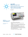
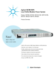
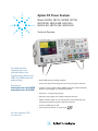
Agilent DC Power Analyzer
Models: N6705A, N6715A, N6705B, N6715B,
N6731B-36B, N6741B-46B, N6751-54A,
N6761A-62A, N6773A-76A, N6781A-82A
Technical Overview
See insights into power
consumption never seen
before with Agilent’s new
2-quadrant source/measure units
(SMUs) and 14585A control and
analysis software
For details visit
www.agilent.com/find/N6700
www.agilent.com/find/14585
• Ideal for R&D testing and design validation
• Sources and measures DC voltage and current into your device under test
• Combines 1 to 4 DC power supplies, DMM, oscilloscope, arbitrary waveform
generator, and datalogger in 1 integrated instrument
• Saves time – no programming required
• Eliminates need to gather and configure multiple instruments
• Flexible, modular system: Can mix and match DC source power levels and
measurement performance levels to optimize investment
• Connect via GPIB, LAN, or USB
• Fully compliant to LXI Class C specification
For Power Solutions in ATE –
See back cover
1
R&D Engineers are
Under Time Pressure
New Instrument Category for R&D Engineers
to Increase Productivity
Due to increasing time-to-market
pressures, research and development
engineers often find themselves
on tight schedule to work through
device under test (DUT) testing.
Along with being driven faster, the
R&D engineers can face a high
regret factor should their haste
result in damaging scarce, complex
or expensive DUTs during product
development. This is a particular
concern when tests involve applying
DC power to a DUT. Furthermore,
test complexity increases when
testing devices that require multiple
input voltages, such as printed circuit boards.
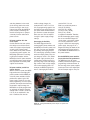
The Agilent N6705 DC Power
Analyzer represents an entirely
new instrument category for R&D
engineers. It provides unrivaled
productivity gains when sourcing and
measuring DC voltage and current
into a DUT. Using the Agilent N6705
DC Power Analyzer, R&D engineers
can gain insights into the DUT’s
power consumption in minutes without writing a single line of code. It
provides an easy-to-use interface,
with all sourcing and measuring
functions available from the front
panel.
Today, when performing DC powerrelated tests, R&D engineers must
gather and configure multiple instruments to complete DC sourcing and
measurement tasks. When executing these complex tasks, which can
involve simultaneously connecting
to and physically interacting with
multiple test instruments, the risk of
error increases. In response, R&D
engineers may choose to automate
tests that are too complex to do
manually. Unfortunately, while automating tasks reduces human error,
writing and debugging programs adds
more work to already overloaded
R&D engineers.
The Agilent N6705 DC power
analyzer saves time
• Provides unrivaled productivity
gains for sourcing and measuring
DC voltage and current into your
DUT by integrating up to four
advanced power supplies with
DMM, scope, arb, and datalogger
features.
• Eliminates the need to gather
multiple pieces of equipment,
create complex test setups including transducers (such as current
probes and shunts) to measure
current into your DUT.
• Eliminates the need to develop
and debug programs to control a
collection of instruments and take
useful measurements because all
the functions and measurements
are available at the front panel.
2
Agilent N6705 DC power analyzer
makes these tasks easy, right from
the front panel
• Setup and view critical turn-on/
turn-off sequences
• Measure and display voltage,
current versus time to visualize
power into the DUT
• Control DC bias supply ramp-up/
down rates
• Generate DC bias supply transients and disturbances
• Log data for seconds, minutes,
hours, or even days to see current
consumption or capture anomalies
• Save data and screen shots to
internal storage or external USB
memory devices
• Save and name your setup and
tests for easy re-use
• Share setups with colleagues
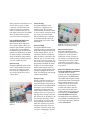
New 14585A control and analysis
software saves even more time
The new 14585A Control and
Analysis Software is a companion PC
application that gives you control of
up to four N6705 mainframes from a
single PC control screen. With this
software, you get improved data
visualization and data management.
Visit www.agilent.com/find/14585
for more information.
Modular System Based on
DC Power Supply Outputs
Feature
Benefit
Integrates capabilities of power supply,
DMM, scope, arb and datalogger
Saves time by eliminating the need to find and
interconnect multiple instruments.
Provides synergistic functions not available
from separately connected instruments.
Large color graphics display
Fast simple quick set up and monitoring.
Ability to visualize results of multiple channels.
Connections and controls
color-coded to the display
Fast set-up and control.
Confidence that you are configured
and testing correctly.
Intuitive, dedicated physical
controls for common functions
Fast set-up and control using a familiar
interface, with each instrument function
behaving like its standalone counterpart.
Access all capabilities
without programming
Reduce 90% of the effort associated with
set-up by eliminating the need for a PC,
drivers, and software.
The Agilent N6705 DC power
analyzer is a modular system that
is tailorable to meet specific test
needs. At the heart of the DC
power analyzer is the DC power
module. The Agilent N6705 DC
power analyzer is a mainframe
that has four slots to accept one
to four DC power modules. Each
DC power module takes one slot,
except for the N6754A 300 W highperformance autoranging DC power
module, which occupies two slots.
This modular design gives you the
flexibility to mix and match over
twenty different DC power modules
to create a solution optimized to
meet specific test requirements:
The N6730, N6740, and N6770 Series
of basic DC power modules
50 W, 100 W, and 300 W;
up to 100 V, up to 20 A
The N6750 Series of high-performance
autoranging DC power modules
50 W, 100 W and 300 W; up to 60 V,
up to 20 A
The N6760 Series of precision
DC power modules
50 W and 100 W; up to 50 V, up to 3 A
The N6780 Series of precision
DC power modules
20 W; up to 20 V, up to ± 3 A
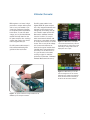
Figure 1. The Agilent N6705 DC power analyzer
3
Voltmeter/Ammeter
R&D engineers can invest in highperformance outputs where speed
and accuracy are needed, or purchase basic performance outputs
for simple DC power requirements.
In the future, as your test needs
change, you can purchase different
modules and swap them into the
DC power analyzer, thus creating a
solution that protects your investment and grows with you.
Each DC power module output is
fully isolated and floating from
ground and from each other.
Each DC power module in the
Agilent N6705 DC power analyzer
has a fully integrated voltmeter and
ammeter to measure the actual
voltage and current being sourced
out of the DC output into the DUT.
Because this voltmeter/ammeter
function is built-in, it is easy to
make measurements without additional wires or the added complexity
of current sense resistors or current
shunts. The accuracy of the voltage
and current measurements are
based on the type of module that is
installed (basic, high-performance,
precision). You can find the accuracy specification in the tables
starting on page 14 under the
performance parameter “Voltmeter/
Ammeter Measurement Accuracy.”
Figure 3. In Meter View, all 4 outputs
can be viewed simultaneously. The both
measured values for voltage and current
and setting for voltage and current are
displayed for each output.
Figure 4. In Meter View, you can also
view an enlarged view of one channel,
displaying many settings and measured
values, for that channel. A summary is
shown for the other three channels.
Figure 2. DC power modules are easily installed into the
N6705 DC power analyzer mainframe.
4
Oscilloscope
Each DC power module in the
Agilent N6705 DC power analyzer
has a fully integrated digitizer to
capture the actual voltage versus
time and current versus time being
sourced out of the DC output into
the DUT. This digitized data is displayed on the large color display
just like an oscilloscope. Because
this oscilloscope function is builtin, it is possible to make current
measurements without current
sense resistors, current shunts, or
current probes. This greatly reduces
measurement setup complexity
and provides for accurate and fully
specified, calibrated measurements.
The accuracy of the measurements
in oscilloscope mode is based on
the type of module that is installed
(basic, high-performance autoranging, precision, and SMU). You can
find this information in the specifications tables starting on page
15 under the performance parameter “Oscilloscope Measurement
Accuracy.”
The N6760 Series of precision DC
power modules offer simultaneous
digitizing of output voltage and output current, such that you can view a
voltage trace and a current trace at
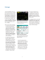
Figure 5. In Scope View, voltage and
current traces are displayed. In this
picture, the DC current flowing into the
DUT is clearly visible as a time-varying
waveform.
the same time on the oscilloscope
display. For all other module types,
you can select to view either a voltage trace or a current trace on the
oscilloscope display.
The digitizer in each module runs
at up to 200 kHz and 512 k samples
per trace. With an effective measurement bandwidth of up to
30 kHz, this oscilloscope function
is perfectly matched to capture
time varying events on the DC output, such as peak current demand,
dropouts, rise times and other DC
transients and disturbances.
5
The oscilloscope can be triggered
on either voltage or current levels.
Because the Agilent N6705 DC
power analyzer is an integrated
instrument, the oscilloscope can
also be easily configured to trigger
on the start of an arbitrary waveform
or to trigger when the DC power
output is enabled. For example, to
make an inrush current measurement on your DUT, you can set the
oscilloscope to trigger on the DC
output’s on/off key, set the trigger
mode to single shot, and then turn
on the DC output. This will immediately capture the current flowing
out of the DC module into the DUT
and give a picture of the inrush current of the DUT. This integrated
functionality is not available when
using a collection of separate test
instruments on the test bench and
is an example of how the DC power
analyzer reduces setup time and
complexity.
Datalogger
The Agilent N6705 DC power analyzer can also function as a datalogger. Using the measurement capability built into each DC power module, the N6705 can continuously log
data to the large color display and
to a file. Data can be logged all four
DC outputs at the same time. The
accuracy of the logged voltage and
current measurements are based on
the type of module that is installed
(basic, high-performance, precision, and SMU).
The maximum datalog file size
is 2 gigabytes, which is approximately 500 million readings. The
logged data file can be stored on
the N6705’s internal non-volatile
RAM or saved externally on a USB
memory device.
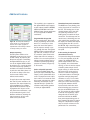
Figure 6. In Datalog View, you can log
data on multiple traces. Here, the current
flowing out of output 1 and output 2 are
captured over 30 seconds
There are two modes of operation:
• In standard mode, measurements
are made spaced apart by the
sample period, which is programmable from 75 milliseconds to
60 seconds. For each DC output,
the logged measurements can be
voltage measurements, current
measurements, or both. Each
reading is an integrated voltage or
current measurement. Standard
mode datalogging is available on
all DC module types.
• In continuously sampled mode,
the built-in digitizer of the DC
power module runs continuously
at 50,000 readings per second.
You can specify a sample period,
which is the period of time during
which these continuous readings
will be accumulated. For each
sample period, one average reading (and optionally, a minimum and
maximum value) will be saved.
In this mode, the digitizer runs
continuously as the readings are
averaged and stored; therefore,
the digitizer is always making
Figure 7. To set up the datalogger,
you use a menu screen to select the
operating parameters. Menu screens like
this are used throughout the DC Power
Analyzer for setup
measurements and no data is
missed. The sample period is
programmable from 1 millisecond
to 60 seconds. In this mode, the
N6760 Series of precision DC
power modules offer simultaneous logging of output voltage and
output current. For all other module types, you can select to log
either voltage or a current when
in continuous sampling mode.
6
The datalogger display can be saved
as a GIF file for use in reports. The
logged data can be saved for viewing at a later time. Logged data can
also be exported to a CSV file that
can be read by most common data
analysis software packages.
Arbitrary Waveform Generator
Each DC power output on the
Agilent N6705 DC power analyzer
can be modulated by the module’s
built-in arbitrary waveform generator function. This permits the DC
output to act as a DC bias transient generator or power arbitrary
waveform generator. The maximum
bandwidth is based on the type of
module that is installed (basic, highperformance, precision, and SMU).
See page 21 for a table that lists the
bandwidth for each DC power module type.
The Agilent N6705 uses run length
encoding, where each point in the
waveform is defined by the voltage setting and the dwell time
or duration to stay at that setting.
Waveforms can be generated by
specifying only a small number of
points. For example, a pulse would
only take three points to define it.
The Agilent N6705 offers the
following waveform choices:
Figure 8. The Arb Selection menu is
used to select which pre-programmed
waveform will be applied to the output of
the DC Power Module. Each of the four
outputs can have a different waveform
applied.
Figure 9. Once you’ve selected a
waveform, you simply fill in the blanks to
describe the waveform.
For each waveform, you can set it
to repeat continuously or you can
specify the number of times the
waveform is repeated. For example,
to generate a pulse train of 10 identical pulses, you can program the
parameters for one pulse and then
specify that you want it to repeat
10 times.
For the user defined voltage and current waveforms, you can download
up to 512 set-points of voltage or
current. For each set-point, a dwell
time is specified and output will
stay (i.e., dwell) at that set-point for
the programmed dwell time value.
For each of the 512 set-points in
the user defined waveform, you can
have a different dwell time from 0
to 262 seconds with 1 microsecond
resolution. The module will step
thru the user defined table of values, staying at each set-point for
the programmed dwell time, and
then it will move on to the next
point. User defined waveforms
can be imported from a CSV file or
directly entered from the front panel
of the DC power analyzer.
Waveform
Number of points per waveform
Sine
100 points
Step
2 points
Ramp
100 points
Pulse
3 points
Stepped ramp (or staircase)
Determined by number of steps you program
Exponential
100 points
User defined voltage waveform
(where the output is a voltage source)
Up to 512 points with point-by-point
adjustable dwell
User defined current waveform
(where the output is a current source)
Up to 64,000 points with programmable dwell
(same for all points)
7
Additional Features
This capability is also supported to
link Agilent N6705 output sequences with outputs installed in N6700B,
N6701A and N6702A Low-Profile
Modular Power System mainframes.
It is not supported on N6700A
mainframes.
Figure 10. The Output On/Off Delays
screen allows you to enter the delay
times for each output. A graphical
representation of the settings is shown
to visually confirm your choices.
Output sequencing
Each DC power module can be
individually set to turn on or to turn
off with a delay. By adjusting the
delay times and then commanding
the Agilent N6705 to turn on, you
can set the Agilent N6705 modules
to sequence on in a particular order.
The same sequencing capability is
available to shut down the modules
in particular order. Delay times can
be set from no delay to one thousand seconds of delay in one
millisecond increments.
For applications that require more
than four DC power modules to be
sequenced, this output sequencing
can be extended across multiple
Agilent N6705 mainframes. By wiring together the I/O ports on the
rear panel of the mainframes, a pair
of synchronization signals is sent
between mainframes, allowing the
output sequences of each mainframe to be synchronized.
Programmable voltage slew
For some applications, like inrush
limiting or powering rate-sensitive
devices, it is necessary to slow
down and control the speed of
the DC output to maintain a specific voltage slew rate. The Agilent
N6705 provides programmable voltage slew rate, so that you can easily control the speed at which the
output slews from one voltage to
another. You can set the speed of a
voltage change anywhere from its
maximum up/down programming
speed to its slowest change of up
to 10 seconds.
Series and parallel operation
To increase available voltage and
power per output, identically rated
outputs can be operated directly in
series. The maximum series operation is 240 V. To increase the available current and power per output,
identically rated outputs can be
operated directly in parallel. The
maximum rated parallel operation
is 100 A per Agilent N6705.
8
Convenient front panel connections
The N6705 uses 3-way binding posts
on the front panel for connection to
the DUT. The binding posts accept
standard banana plugs, bare wire,
and spade-lug connectors. The
binding posts are rated for 20 A per
connection. To avoid setup and connection errors, the binding posts are
color-coded to the control keys and
the display. For modules with outputs
rated at greater than 20 A, such as
the N6753A, high current wires must
be brought out through the N6705’s
rear panel.
4-wire sensing for improved
measurement accuracy
To improve the voltage measurement
accuracy and regulation of the DC
outputs, the Agilent N6705 DC
power analyzer offers 4-wire sensing capability, also called remote
sensing, on each of the four outputs
of the DC power analyzer. 4-wire
remote sensing is useful when the
DUT draws high current and you
want to account for voltage drop
in the power leads to achieve tight
regulation and high voltage measurement accuracy. To use 4-wire
sensing, in addition to your power
leads, you connect two low current
sensing leads between the DUT
input terminals and 4-wire sense
terminal binding posts located on
the front of the N6705 power supply. This permits the output module
to monitor and regulate its output
voltage directly at the DUT input
terminals instead of the N6705
front panel output binding posts. It
then automatically adjusts its output
voltage to compensate for voltage
drops across the resistance in the
power leads. For convenience,
switching between 2-wire mode
(local sensing) and 4-wire mode
(remote sensing) is done via an
internal relay inside the N6705 DC
power analyzer, eliminating the
need for shorting bars or jumpers
commonly found on other bench
power sources.
DC power modules offer low
noise outputs
Careful attention has been paid to
this design to ensure low normal
mode noise (ripple and peak-peak)
as well as low common mode
noise. While all DC power modules
are switching power supplies, the
N6750 high-performance autoranging DC power modules and the
N6760 precision DC power modules
are switching power supply designs
that outperform most linear power
supplies on the market.
DC power modules provide fast
voltage changes
When it comes to speed, the N6750
high-performance autoranging DC
power modules and the N6760 precision DC power modules achieve
performance unlike a typical DC
power supply. Thanks to an active
down-programming circuit to rapidly
pull down the output when lowering
the module’s output voltage, the
N6750/60 can rapidly program both
up and down in voltage. Changing
voltage from 0 V to 50 V, or 50 V to
0 V, can be accomplished in less
than 1.5 milliseconds. And for
smaller voltage changes, for
example from 0 V to 5 V or 5 V to
0 V, the programming speed is less
than 200 microseconds. These output speeds allow the N6750/60 to
give maximum system throughput
when your test calls for frequent
changes in power supply voltage
settings.
Autoranging for flexibility
The N6750 high-performance
autoranging DC power modules and
the N6760 precision DC power modules give you even more flexibility
by providing autoranging outputs.
This autoranging capability provides
maximum output power at any output voltage up to 50 V. This allows
one power supply to do the job of
several power supplies because its
operating range covers low voltage,
high current as well as high voltage,
low current operating points. For
example, the N6751A high-performance, autoranging DC module,
rated at 50 V, 5 A, and
50 W can provide full power at
10 V @ 5 A (=50 W),
20 V @ 2.5 A (= 50 W),
33.3 V @ 1.5 A (= 50 W),
50 V @ 1 A (= 50 W)
or anywhere in between. Therefore,
this 50 W autoranging power supply,
due to its extended voltage and
current range, can produce voltage
and current combinations in the
range of a 250 W non-autoranging
power supply. See page 27 for a
diagram describing the details of the
autoranging output characteristics
of the N6750 and N6760 families of
DC power modules.
Use the N6760 DC power modules
for precision low-level performance
The N6760 precision DC power
modules provide dual ranges on both
programming and measurement. In
the low range, these power supplies
provide precision in the milliampere
and microampere regions. They are
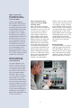
Figure 11. The Agilent N6705 DC power analyzer is a perfect size
for the bench.
9
ideally suited for semiconductor and
passive device testing, or where
a precisely controlled output and
highly accurate, precise measurements are needed during test. For
even higher performance, the N6780
Series of SMU modules provides
accuracies down to nanoamperes.
Use the N6730/40/70 DC power
modules for basic DC bias
Not all testing require high performance power supplies. When your
budget is tight and when speed and
accuracy are a low consideration,
the N6730 Series of 50 W DC power
modules, the N6740 Series of 100 W
DC power modules, and the N6770
Series of 300 W DC power modules
are an economical solution that give
you clean, reliable DC power.
Real time clock
The Agilent N6705 DC power analyzer has a built-in battery backed real
time clock. This allows for proper
time-stamping of logged data. It is
also used to tag files with correct
creation dates.
Figure 12. The N6705’s front panel
USB port
Internal memory
The Agilent N6705 DC power
analyzer has 1 gigabyte of nonvolatile storage. This storage is
shared between the four DC outputs.
It can be used for saving test setups,
test results, and screen images.
External USB storage is supported
for increased storage capacity to
log data longer (see section “Front
Panel USB”).
Front panel USB
The Agilent N6705 DC Power
Analyzer provides a convenient front
panel USB port designed exclusively
for data storage devices, such as
USB memory devices or USB hard
drives. On devices connected to this
USB port, you can save test setups,
test results, and screen images. It is
also an easy way to move test setup
files between two N6705 DC Power
Analyzers or test results between
the DC Power Analyzer and a PC.
You can also log data directly to the
USB device plugged into the front
panel. This extends the total storage
capability of the N6705.
Emergency stop
Should a hazardous situation occur
during testing, you can press the
large red Emergency Stop button on
the front panel of the Agilent N6705.
Pressing this easy-to-find button
immediately removes power from
the DC outputs. However, any data
collection (such as a scope trace or
data log) that is running at the time
will continue to run. By doing so, the
data you were collecting is saved
and you will get a record of what
was happening at the time of the
event that caused you to press the
Emergency Stop button. The measurements could aid in failure analysis, repair, or debugging of the DUT.
10
Figure 13. The Emergency Stop button
shuts down all outputs immediately
DUT protection features
Each Agilent N6705 DC power
module is protected against overvoltage, over-current, and overtemperature. A fault condition in
one module can be detected within
10 microseconds by other modules
so that they can be quickly shut
down to avoid hazardous conditions
on your DUT.
New Source/Measure Unit modules
for the most demanding applications
The N6780 Series of source/
measure units offer the highest level
of performance in the N6700 Series.
These SMUs feature highly accurate
measurements down to nanoamperes
while providing operation as a DC
voltage source, DC current source,
and electronic load. For details
on these new products and how
they can be used for applications
including battery drain analysis and
functional test, visit www.agilent.
com/find/N6780 and download
the N6780 Series Source/Measure
Units (SMUs) for the N6700 Modular
Power System Data Sheet, literature
number 5990-5829EN.
Output disconnect and polarity
reversal relays
Modules in the Agilent N6705 can
be individually ordered with optional
Output Disconnect Relays (option
761) or Output Disconnect/Polarity
Reversal Relays (option 760). See
table on page 29 for option 760 and
761 availability. All relays are built
into the module, so no additional
wiring is needed to get the relay
function. With option 761, Output
Disconnect Relays, an emergency
condition or turning the DC output
off causes mechanical relays disconnect both the plus and minus
side of the power supply, including the sense leads. With option
760, Output Disconnect/Polarity
Reversal Relays, mechanical relays
switch the leads on both the plus
and the minus side of the power
supply, including the sense leads,
resulting in a voltage polarity reversal at the DUT. In addition to polarity reversal, option 760 provides the
same output disconnect function as
option 761.
Note: Output current is limited
on some modules when option
760 Output Disconnect/Polarity
Reversal Relays is installed. See the
“Available options” tables at the
bottom of page {29 and page 31} for
more information about maximum
current limitations with
option 760.
Triggering
The Agilent N6705 DC power
analyzer has hardware trigger in/
trigger out signals which permit
the Agilent N6705 to be synchronized with other test equipment.
For example, when you turn on the
outputs of the Agilent N6705, it can
generate a trigger signal to start a
measurement on an RF power meter.
Connectivity
The Agilent N6705 DC power
analyzer comes standard with
GPIB, USB 2.0, and 10/100 base-T
ethernet LAN interfaces. The Agilent
N6705 is fully compliant with the
LXI class C specification.
Security
All non-volatile RAM data and
settings can be cleared from the
front panel. For customers who
have security concerns about USB
access to internally stored test data
and setups, the Agilent N6705 also
offers option AKY, which removes
the USB ports from the front and
rear of the Agilent N6705. When
used in systems running GPIB, the
LAN and/or USB interfaces can be
disabled for extra security.
Control from any browser
The Agilent N6705 can be controlled
via a standard web browser. The
Agilent N6705 contains a web
server that provides a webpage
containing a graphical front panel
representation of the Agilent N6705
front panel. The WebGUI operation
is identical to operating the real
front panel on the Agilent N6705 DC
power analyzer.
11
New 14585 Control & Analysis
Software
Control up to four N6705 mainframes. For more details visit
www.agilent.com/find/14585
Drivers
For customers who wish to operate the DC Power Analyzer under
computer control, the Agilent N6705
comes with both VXIplug&play drivers and IVI-COM drivers. LabView
drivers are available at NI.COM.
Programming language
The Agilent N6705 supports
SCPI (Standard Commands for
Programmable Instruments). Note
that the Agilent N6705’s command
set is compatible with the N6700
modular power system for ATE,
so programs written for the
Agilent N6700 will work on the
Agilent N6705.
Firmware updates
The Agilent N6705 firmware is
stored in FLASH ROM and can be
easily updated when new features
become available. Firmware can be
downloaded into the Agilent N6705
over GPIB, LAN, or USB using the
supplied firmware update utility
program. Firmware updates can be
found at www.agilent.com/find/
N6705firmware.
Makes a great tool for
ATE systems that require
an advanced user interface
for test and debug
While the Agilent N6705 DC
power analyzer is designed primarily as an R&D bench tool, customers building ATE systems may find
the Agilent N6705 has great utility
in an ATE system. It is fully programmable, LXI class C certified,
and takes the same commands as
the Agilent N6700. But thanks to its
large display and easy to use controls, test engineers may find the
Agilent N6705 makes a great tool
for visualizing test results as the
tests execute, for DUT troubleshooting, for DUT debugging, and f o r
A T E t est deve l o p m e n t , T h e
Agilent N6705 mounts in a standard
19” rack using standard rack mount
hardware for 4 U instruments.
Achieve correlation and
share data between R&D
and manufacturing
Power management feature
allows you to allocate N6705
mainframe power
Often, a DUT requires some high
power DC sources and several very
low power DC sources. In this case,
you may choose to configure a
system where the sum of the
power modules installed in the
Agilent N6705 exceeds the total
power available from the Agilent
N6705 mainframe. The power management features of the Agilent
N6705 allow you to allocate mainframe power to the outputs where
it’s needed, achieving maximum
asset utilization and flexibility. This
feature provides safety from unexpected and dangerous shutdowns
that can occur with power systems
without power management when
operated in a similar way. For
example, if your DUT requires
The Agilent N6705 DC power
analyzer is a modular system that
uses the same DC power modules
as the N6700 low-profile modular
power system for ATE. Customers
who use the N6705 in R&D and
the N6700 in Manufacturing
can easily achieve test correlation
between R&D testing, design
characterization/validation testing,
and manufacturing testing because
the DC power modules are common
to both the bench and ATE versions
of the product. Test programs can
be easily shared between R&D and
manufacturing since the Agilent
N6705 and the Agilent N6700 share
a common command set.
12
250 W on two of its inputs, but only
10 W each two auxiliary inputs, you
can configure a system consisting
of two 300 W DC modules and two
50 W DC modules. Even though the
sum of the module power is greater
than 600 W, you can still use the
Agilent N6705. Thanks to the power
management feature, you can allocate the 250 W each to the two
300 W modules while you allocate
only 25 W to each of the 50 W
modules.
Universal AC input
The Agilent N6705 has a universal
input that operates from 100-240
VAC, 50/60/400 Hz. There are no
switches to set or fuses to change
when switching from one voltage
standard to another. The AC input
employs power factor correction.
Choosing the Right DC Power Modules to Meet Your Testing Needs
See detailed specifications on page 14
N6780 Series
For applications where multiquadrant operation and highprecision are required
N6750 Series
For applications where the power
supply plays a critical role
The Agilent N6750 Series of highperformance, auto ranging DC
power modules provides low noise,
high accuracy and output voltage changes that are up to 10 to
50 times faster than other power
supplies. In addition, auto ranging
output capabilities enable one power
supply to do the job of several
traditional power supplies. The
N6750 Series combines widest the
arbitrary waveform generator bandwidth, available power up to 300 W,
and high accuracy measurements.
In oscilloscope mode, they can be
configured to display either a voltage or a current trace. The N6753A
is supported in the N6705B only.
For details on these new products
and how they can be used for
applications including battery drain
analysis and functional test, visit
www.agilent.com/find/N6780 and
download the N6780 Series Source/
Measure Units (SMUs) for the N6700
Modular Power System Data Sheet,
literature number 5990-5829EN.
N6760 Series
For applications where
precision is required
The Agilent N6760 Series of precision DC power modules provides
fast outputs changes (for wide
arbitrary waveform generator
bandwidth) and 16-bit voltage and
current programming, and 18-bit
measurements for precision in
the milliampere and microampere
region. In oscilloscope mode, the
N6760 Series offers the ability to
view both a voltage and a current
trace simultaneously.
13
N6730/40/70 Series
For basic DC applications
The Agilent N6730, N6740 and
N6770 families of DC power modules
provide programmable voltage and
current, measurement and protection features at a very economical
price. These modules offer a wide
range of voltage, current, and power
outputs. In oscilloscope mode, they
can be configured to display either
a voltage or a current trace.
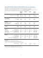
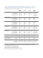
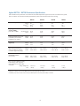
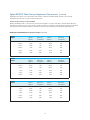
Agilent N6751A/N6752A, N6754A and N6761A/N6762A Performance Specifications
Unless otherwise noted, specifications are warranted over the ambient temperature range of 0 to 55°C after a 30-minute warm-up period,
with each module’s sense terminals externally jumpered directly to their respective output terminals (local sensing).
Note: Performance specifications for the N6780 SMU modules can be found at www.agilent.com/find/N6780. See the N6780 Series Source/
Measure Units (SMUs) for the N6700 Modular Power System Data Sheet, literature number 5990-5829EN.
N6751A /
N6752A
N6753A
N6754A
N6761A /
N6762A
50 V
5 A / 10 A
50 W / 100 W
20 V
50 A
300 W
60 V
20 A
300 W
50 V
1.5 A / 3 A
50 W / 100 W
4.5 mV
350 µV
5 mV
1 mV
6 mV
1 mV
4.5 mV
350 µV
Voltage
Current (@ 0 - 7 V)
(@ 0 - 50 V)
2 mV
2 mA
2 mA
2 mV
12 mA
12 mA
2 mV
5 mA
5 mA
0.5 mV
30 µA
65 µA
Voltage
Current
1 mV
1 mA
0.5 mV
5 mA
1.2 mV
2 mA
0.5 mV
30 µA
0.06% + 19 mV
N/A
0.1% + 20 mA
N/A
N/A
0.06% + 10 mV
N/A
0.10% + 30 mA
N/A
N/A
0.06% + 25 mV
N/A
0.10% + 8 mA
N/A
N/A
0.016% + 6 mV
0.016% + 1.5 mV
0.04% + 200 µA
0.04% + 15 µA
0.04% + 55 µA
0.05% + 20 mV
N/A
0.1% + 4 mA
N/A
N/A
0.05% + 10 mV
N/A
0.10% + 30 mA
N/A
N/A
0.05% + 25 mV
N/A
0.10% + 8 mA
N/A
N/A
0.016% + 6 mV
0.016% + 1.5 mV
0.04% + 160 µA
0.03% + 15 µA NOTE 2
0.03% + 55 µA
± 30 mV
< 100 µs
± 90 mV NOTE 3
< 100 µs
± 75 mV
< 100 µs
DC output ratings
Voltage
Current (derated 1% per °C above 40°C)
Power
Output ripple
and noise (PARD)
(from 20 Hz – 20 MHz)
Load effect
(Regulation)
(for any output load change,
with a maximum load-lead
drop of 1 V per lead)
Source effect
(Regulation)
CV peak-to-peak
CV rms
Programming
accuracy
(at 23°C ±5°C
Voltage high range
after 30 minute
Voltage low range (≤ 5.5 V)
warm-up. Applies
Current high range
from min. to max.
Current low range (≤ 100 mA, @ 0 - 7 V)
programming range)
(≤ 100 mA, @ 0 - 50 V)
Measurement
accuracy
(at 23°C ±5°C)
Voltage high range
Voltage low range (≤ 5.5 V)
Current high range
Current low range (≤ 100 mA, @ 0 - 7 V) NOTE 1
(≤ 100 mA, @ 0 - 50 V)
Load transient
recovery time
(time to recover to within the settling band following a load change)
• from 60% to 100% and from 100% to 60% of full load for models N6751A & N6761A
• from 50% to 100% and from 100% to 50% of full load for models N6752A-N6754A & N6762A.
Voltage settling band
Time
± 75 mV NOTE 2
< 100 µs
1 Applies when measuring 4096 data points (SENSe:SWEep:POINts = 4096).
2 Settling band is ±125 mV for Model N6752A when relay option 761 is installed.
3 Settling band is ±350 mV for Model N6754A when relay option 760 or 761 is installed.
14
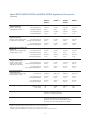
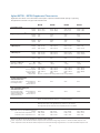
Agilent N6751A/N6752A, N6754A and N6761A/N6762A Supplemental Characteristics
Supplemental characteristics are not warranted but are descriptions of performance determined either by design or type testing.
All supplemental characteristics are typical unless otherwise noted.
N6751A /
N6752A
N6753A
N6754A
N6761A /
N6762A
10 mV – 24.48 V
N/A
50 mA – 51 A
25 mV – 61.2 V
N/A
20 mA – 20.4 A
Current low range (≤ 0.1 A)
20 mV – 51 V
N/A
10 mA – 5.1 A/
10 mA – 10.2 A
N/A
N/A
N/A
15 mV – 51 V
12 mV – 5.5 V
1 mA – 1.53 A/
1 mA – 3.06 A
0.1 mA – 0.1 A NOTE 1
Voltage high range
Voltage low range (≤ 5.5 V)
Current high range
Current low range (≤ 0.1 A)
3.5 mV NOTE 2
N/A
3.25 mA NOTE 4
N/A
1.5 mV NOTE 2
N/A
16.3 mA NOTE 4
N/A
4.2 mV NOTE 2
N/A
6.5 mA NOTE 4
N/A
880 µV NOTE 3
90 µV
60 µA
2 µA
Voltage high range
Voltage low range (≤ 5.5 V)
Current high range
Current low range (≤ 0.1 A)
1.8 mV NOTE 5
N/A
410 µA
N/A
0.8 mV NOTE 5
N/A
2.05 mA
N/A
2.2 mV NOTE 5
N/A
820 µA
N/A
440 µV NOTE 6
44 µV
30 µA
1 µA
Voltage high range
Voltage low range (≤ 5.5 V)
Current high range
Current low range (≤ 0.1 A)
18 ppm + 160 µV
N/A
100 ppm + 45 µA
N/A
20 ppm + 20 µV
N/A
60 ppm + 500 µA
N/A
20 ppm + 50 µV
N/A
60 ppm + 200 µA
N/A
18 ppm + 140 µV
40 ppm + 70 µV
33 ppm + 10 µA
60 ppm + 1.5 µA
Voltage high range
Voltage low range (≤ 5.5 V)
Current high range
Current low range (≤ 0.1 A)
25 ppm + 35 µV
N/A
60 ppm + 3 µA
N/A
20 ppm + 20 µV
N/A
60 ppm + 30 µA
N/A
20 ppm + 50 µV
N/A
60 ppm + 12 µA
N/A
23 ppm + 40 µV
30 ppm + 40 µV
40 ppm + 0.3 µA
50 ppm + 0.3 µA
2 mA
10 mA
4 mA
2 mA
500 µA
< 2 mA
500 µA
2 mA
750 µA
3 mA
500 µA
< 2 mA
Programming ranges
Voltage high range
Voltage low range (≤ 5.5 V)
Current high range
Programming resolution
Measurement resolution
Programming temperature
coefficient per °C
Measurement temperature
coefficient per °C
Output ripple and noise (PARD)
CC rms
Common mode noise
(from 20 Hz – 20 MHz;
from either output to chassis)
rms
peak-to-peak
Over-voltage protection
Accuracy
Maximum setting
Response time
0.25% + 250 mV
0.25% ±150 mV
0.25% ±300 mV
0.25% + 250 mV
55 V
22 V
66 V
55 V
50 µs from occurrence of over-voltage condition to start of output shutdown
1 If you are operating the unit below 255 µA in constant current mode, the output may become unregulated with the following load conditions:
The load resistance is <175 mΩ and the load inductance is >20 µH. If this occurs, an UNRegulated flag will be generated and the output current may rise
above the programmed value but will remain less than 255 µA.
2 Based on 14-bit DAC, with DAC range adjusted by software calibration
3 Based on 16-bit DAC, with DAC range adjusted by software calibration
4 Based on 12-bit DAC, with DAC range adjusted by software calibration
5 Based on 16-bit ADC (15 bits plus sign), with ADC range adjusted by software calibration
6 Based on 18-bit ADC (17 bits plus sign), with ADC range adjusted by software calibration
15
Agilent N6751A/N6752A, N6754A and N6761A/N6762A Supplemental Characteristics
(Continued)
N6751A /
N6752A
N6753A NOTE 4
N6754A
N6762A
N6761A /
For voltage change of
up-programming time
0 to 10 V
0.2 ms
0 to 6 V
0.3 ms
0 to 15 V
0.35 ms
0 to 10 V
0.6 ms
For voltage change of
up-programming time
0 to 50 V
1.5 ms
0 to 20 V
1.5 ms
0 to 60 V
2.0 ms
0 to 50 V
2.2 ms
Maximum up-programming settling time
with full resistive load
(time from start of voltage change
For voltage change of
to within 50 mV of final value)
up-programming settling time
0 to 10 V
0.5 ms
0 to 6 V
2.0 ms
0 to 15 V
0.8 ms
0 to 10 V
0.9 ms
For voltage change of
up-programming settling time
0 to 50 V
4.0 ms
0 to 20 V
3.0 ms
0 to 60 V
4.2 ms
0 to 50 V
4.0 ms
For voltage change of
down-programming time
10 to 0 V
0.3 ms
6 to 0 V
0.5 ms
15 to 0 V
0.6 ms
10 to 0 V
0.3 ms
For voltage change of
down-programming time
50 to 0 V
1.3 ms
20 to 0 V
1.6 ms
60 to 0 V
2.2 ms
50 to 0 V
1.3 ms
10 to 0 V
0.45 ms
6 to 0 V
0.7 ms
15 to 0.8 V
0.8 ms
10 to 0 V
0.45 ms
50 to 0 V
1.4 ms
20 to 0 V
3.0 ms
60 to 0 V
2.3 ms
50 to 0 V
1.4 ms
1000 µF NOTE 1
4700 µF NOTE 2
680 µF NOTE 3
1000 µF NOTE 1
For voltage change of
down-programming time
10 to 0 V
0.3 ms
6 to 0 V
0.5 ms
15 to 0 V
2.3 ms
10 to 0 V
0.3 ms
For voltage change of
down-programming time
50 to 0 V
1.3 ms
20 to 0 V
1.6 ms
60 to 0 V
10.0 ms
50 to 0 V
1.3 ms
7W
7A
12.5 W
15 A
12.5 W
6A
7W
3.8 A
Maximum up-programming time
with full resistive load
(time from 10% to 90%
of total voltage excursion)
Maximum down-programming time
with no load
(time from start of voltage change
to output voltage < 0.5 V)
Maximum down-programming
settling time with no load
(time from start of voltage
For voltage change of
change to output voltage
down-programming settling time
within 50 mV of final value)
For voltage change of
down-programming settling time
Down-programming time
with capacitive load NOTE 1
(time from start of voltage change
to output voltage < 0.5 V)
Capacitive load
Down-programming capability
Continuous power
Peak current
Remote sense capability
Outputs can maintain specifications
with up to a 1-volt drop per load lead.
Series and parallel operation
Identically rated outputs can be operated directly in
parallel or can be connected for straight series operation.
Auto-series and auto-parallel operation is not available.
1
2
3
4
Modules can discharge a 1000 µF capacitor from 50 V to 0 V at a rate of 4 times/second.
Modules can discharge a 4700 µF capacitor from 20 V to 0 V at a rate of 4 times/second.
Modules can discharge a 680 µF capacitor from 60 V to 0 V at a rate of 4 times/second.
N6753A is supported in the N6705B only. It requires special installation instructions that ship with the module.
16
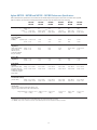
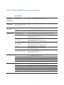
Agilent N6731B – N6736B and N6741B – N6746B Performance Specifications
Unless otherwise noted, specifications are warranted over the ambient temperature range of 0 to 55°C after a 30-minute warm-up period,
with each module’s sense terminals externally jumpered directly to their respective output terminals (local sensing)
N6731B/
N6741B
N6732B/
N6742B
N6733B/
N6743B
N6734B/
N6744B
N6735B/
N6745B
N6736B/
N6746B
5V
10 A / 20 A
50 W / 100 W
8V
6.25 A / 12.5 A
50 W / 100 W
20 V
2.5 A / 5 A
50 W / 100 W
35 V
1.5 A / 3 A
52.5 W / 105 W
60 V
0.8 A / 1.6 A
50 W / 100 W
100 V
0.5 A / 1 A
50 W / 100 W
CV rms
10 mV / 11 mV
2 mV
12 mV
2 mV
14 mV
3 mV
15 mV
5 mV
25 mV
9 mV
30 mV
18 mV
Voltage
Current
5 mV
2 mA
6 mV
2 mA
9 mV
2 mA
11 mV
2 mA
13 mV / 16 mV
2 mA
20 mV / 30 mV
2 mA
Voltage
Current
1 mV
1 mA
2 mV
1 mA
2 mV
1 mA
4 mV
1 mA
6 mV
1 mA
10 mV
1 mA
0.1% + 19 mV
0.15% + 20 mA
0.1% + 19 mV
0.15% + 20 mA
0.1% + 20 mV
0.15% + 20 mA
0.1% + 35 mV
0.15% + 20 mA
0.1% + 60 mV
0.15% + 20 mA
0.1% + 100 mV
0.15% + 10 mA
0.1% + 20 mV
0.15% + 20 mA
0.1% + 20 mV
0.15% + 10 mA
0.1% + 20 mV
0.15% + 5 mA
0.1% + 35 mV
0.15% + 4 mA
0.1% + 60 mV
0.15% + 4 mA
0.1% + 100 mV
0.15% + 2 mA
± 0.2 V / 0.3 V
< 200 µs
± 0.4 V / 0.5 V
< 200 µs
± 0.5 V / 1.0 V
< 200 µs
DC output ratings:
Voltage
Current NOTE 1
Power
Output ripple
and noise (PARD)
(from 20 Hz –
20 MHz)
CV peak-to- peak
Load effect
(Regulation)
(with output change
from no load to
full load, up to a
maximum load-lead
drop of 1 V/lead)
Source effect
(Regulation)
Programming
accuracy
(@ 23 °C ±5°C after
Voltage
30 minute warm-up.
Current
Applies from minimum
to maximum programming range)
Voltmeter/ammeter
measurement accuracy
(at 23°C ±5°C)
Voltage
Current
NOTE 3
Load transient
recovery time
(time to recover to within the settling band following a load
change from 50% to 100% and from 100% to 50% of full load.)
Voltage settling band
Time
±0.08 V / 0.1 V NOTE 2 ±0.08 V / 0.1 V NOTE 2 ± 0.2 V / 0.3 V
< 200 µs
< 200 µs
< 200 µs
1 Output current is derated 1% per °C above 40°C.
2 Settling band is ±0.10 V/0.125 V for 5 V and 8 V Models when relay options 760 and 761 are installed.
3 For N6742B, output current is limited to 10 A when option 760 Output Disconnect/Polarity Reversal Relays is installed.
17
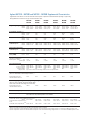
Agilent N6731B – N6736B and N6741B – N6746B Supplemental Characteristics
Supplemental characteristics are not warranted but are descriptions of performance determined either by design or type testing.
All supplemental characteristics are typical unless otherwise noted.
Programming ranges
N6731B/
N6741B
N6732B/
N6742B
N6733B/
N6743B
N6734B/
N6744B
N6735B/
N6745B
N6736B/
N6746B
15 mV – 5 .1 V
60 mA – 10.2 A/
60 mA – 20.4 A
15 mV – 8 .16 V
40 mA –6.375 A/
40 mA – 12.75 A
30 mV – 20.4 V
10 mA – 2.55 A/
10 mA – 5.1 A
40 mV – 35.7 V
5 mA – 1.53 A/
5 mA – 3.06 A
70 mV – 61.2 V
2.5 mA – 0.85 A/
2.5 mA – 1.7 A
100 mV – 102 V
1.5 mA – 0.51 A/
1.5 mA – 1.02 A
3.5 mV
7 mA
4 mV
4 mA
7 mV
3 mA
10 mV
2 mA
18 mV
1 mA
28 mV
0.5 mA
3 mV
10 mA
4 mV
7 mA
10 mV
3 mA
18 mV
2 mA
30 mV
1 mA
50 mV
0.5 mA
0.005% + 0.1 mV
0.005% + 1 mA
0.005% + 0.1 mV
0.005% + 0.5 mA
0.005% + 0.2 mV
0.005% + 0.1 mA
0.005% + 0.5 mV
0.005% + 0.05 mA
0.005% + 0.5 mV
0.005% + 0.02 mA
0.005% + 1 mV
0.005% + 0.02 mA
Current
0.01% + 0.1 mV
0.01% + 1 mA
0.01% + 0.1 mV
0.01% + 0.5 mA
0.01% + 0.2 mV
0.01% + 0.1 mA
0.01% + 0.2 mV
0.01% + 0.05 mA
0.01% + 0.5 mV
0.01% + 0.02 mA
0.01% + 0.5 mV
0.01% + 0.02 mA
CC rms
8 mA
4 mA
2 mA
2 mA
2 mA
2 mA
1 mA
< 15 mA
1 mA
< 10 mA
1 mA
< 10 mA
1 mA
< 10 mA
1 mA
< 10 mA
1 mA
< 10 mA
0.25% + 200 mV
0.25% + 300 mV
0.25% + 300 mV
66 V
0.25% + 250 mV
0.25% + 300 mV
0.25% + 300 mV
110 V
20 ms
20 ms
20 ms
100 ms
100 ms
100 ms
Voltage
Current
Programming resolution NOTE 1
Voltage
Current
Measurement resolution NOTE 2
Voltage
Current
Programming temperature
coefficient per °C
Voltage
Current
Measurement temperature
coefficient per °C
Voltage
Output ripple and
noise (PARD)
Common mode noise
(from 20 Hz – 20 MHz; from
either output to chassis)
rms
peak-to-peak
Over-voltage protection
Accuracy
Accuracy w/opt 760
Accuracy w/opt 761
Maximum setting
Response time
0.25% + 50 mV
0.25% + 50 mV
0.25% + 75 mV
0.25% + 100 mV
0.25% + 600 mV
0.25% + 600 mV
0.25% + 350 mV
0.25% + 250 mV
0.25% + 600 mV
0.25% + 600 mV
0.25% + 350 mV
0.25% + 250 mV
7.5 V
10 V
22 V
38.5 V
50 µs from occurrence of over-voltage condition to start of output shutdown
Maximum up-programming and down-programming time with full resistive load
(time from 10% to 90% of total voltage excursion)
Voltage setting from 0 V to
full scale and full scale to 0 V
20 ms
20 ms
20 ms
Maximum up-programming and down-programming settling time with full resistive load
(time from start of voltage change until voltage settles
within 0.1% of the full-scale voltage of its final value)
Voltage setting from 0 V to
full scale and full scale to 0 V
100 ms
100 ms
100 ms
Remote sense capability
Outputs can maintain specifications with up to a 1-volt drop per load lead.
Series and parallel operation
Identically rated outputs can be operated directly in parallel or can be connected for straight series operation.
Auto-series and auto-parallel operation is not available.
Oscilloscope measurement accuracy
(at 23°C ±5°C, Accuracy of any individual point in the trace)
Voltage
0.1% + 25 mV
0.1% + 30 mV
Current with current compensation on NOTE 3
0.15% + 70 mA
+ 7 mA
Current with current compensation off NOTE 4 0.15% + 50 mA
0.15% + 30 mA
1
2
3
4
0.1% + 45 mV
0.15% + 40 mA
0.1% + 75 mV
0.15% + 20 mA
0.1% + 130 mV
0.15% + 14 mA
0.1% + 190 mV
0.15% + 12 mA 0.15%
0.15% + 15 mA
0.15% + 10 mA
0.15% + 9 mA
0.15% + 5 mA
Based on 12-bit DAC, with DAC range adjusted by software calibration
Based on 12-bit ADC (11 bits plus sign), with ADC range adjusted by software calibration
Current compensation on means the selection labeled “Compensate current measurements during voltage transients” is checked on the Meter Properties screen
Current compensation off means the selection labeled “Compensate current measurements during voltage transients” is not checked on the Meter Properties screen
18
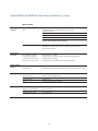
Agilent N6773A – N6776A Performance Specifications
Unless otherwise noted, specifications are warranted over the ambient temperature range of 0 to 55°C after a 30-minute warm-up period,
with each module’s sense terminals externally jumpered directly to their respective output terminals (local sensing).
N6773A
N6774A
N6775A
N6776A
20 V
15 A NOTE 3
300 W
35 V
8.5 A
300 W
60 V
5A
300 W
100 V
3A
300 W
20 mV
3 mV
22 mV
5 mV
35 mV
9 mV
45 mV
18 mV
Voltage
Current
13 mV
6 mA
16 mV
6 mA
24 mV
6 mA
45 mV
6 mA
Voltage
Current
2 mV
1 mA
4 mV
1 mA
6 mV
1 mA
10 mV
1 mA
Voltage
Current
0.1% + 20 mV
0.15% + 60 mA
0.1% + 35 mV
0.15% + 60 mA
0.1% + 60 mV
0.15% + 60 mA
0.1% +100 mV
0.15% + 30 mA
Voltage
Current
0.1% + 20 mV
0.15% + 15 mA
0.1% + 35 mV
0.15% + 12 mA
0.1% + 60 mV
0.15% + 12 mA
0.1% +100 mV
0.15% + 6 mA
± 0.3 V NOTE 2
< 250 µs
± 0.3 V NOTE 2
< 250 µs
± 0.5 V
< 250 µs
± 1.0 V
< 250 µs
DC output ratings
Voltage
Current NOTE 1
Power
Output ripple
and noise (PARD)
(from 20 Hz – 20 MHz)
CV peak-to- peak
CV rms
Load effect (Regulation)
(with output change from no load
to full load, up to a maximum
load-lead drop of 1 V/lead)
Source effect
(Regulation)
Programming accuracy:
(@ 23°C ±5°C after 30 minute
warm-up. Applies from minimum
to maximum programming range)
Voltmeter/ammeter
measurement accuracy
(at 23°C ±5°C)
Load transient recovery time
(time to recover to within the settling
band following a load change from
50% to 100% and from 100% to 50%
of full load.)
Voltage settling band
Time
1 Output current is derated 1% per °C above 40°C.
2 Settling band is ±0.35 V for 20 V and 35 V Models when relay options 760 and 761 are installed.
3 For N6773A, output current is limited to 10 A when option 760 Output Disconnect/Polarity Reversal Relays is installed.
19
Agilent N6773A – N6776A Supplemental Characteristics
Supplemental characteristics are not warranted but are descriptions of performance determined either by design or type testing.
All supplemental characteristics are typical unless otherwise noted
N6773A
N6774A
N6775A
N6776A
Voltage
Current
30 mV – 20.4 V
30 mA – 15.3 A
40 mV – 35.7 V
15 mA – 8.67 A
70 mV – 61.2 V
7.5 mA – 5.1 A
100 mV – 102 V
4.5 mA – 3.06 A
Voltage
Current
7 mV
9 mA
10 mV
6 mA
18 mV
3 mA
28 mV
1.5 mA
Voltage
Current
10 mV
9 mA
18 mV
6 mA
30 mV
3 mA
50 mV
1.5 mA
Voltage
Current
0.01% + 0.2 mV
0.01% + 0.5 mA
0.01% + 0.5 mV
0.01% + 0.5 mA
0.01% + 0.5 mV
0.01% + 0.1 mA
0.01% + 1 mV
0.01% + 0.1 mA
Voltage
Current
0.01% + 0.2 mV
0.01% + 0.5 mA
0.01% + 0.2 mV
0.01% + 0.5 mA
0.01% + 0.5 mV
0.01% + 0.05 mA
0.01% + 0.5 mV
0.01% + 0.05 mA
CC rms
6 mA
6 mA
6 mA
6 mA
2 mA
< 20 mA
2 mA
< 20 mA
2 mA
< 20 mA
2 mA
< 20 mA
Programming ranges
Programming resolution NOTE 1
Measurement resolution NOTE 2
Programming temperature
coefficient per °C
Measurement temperature
coefficient per °C
Output ripple and noise (PARD)
Common mode noise
(from 20 Hz – 20 MHz; from
either output to chassis)
Rms
Peak-to- peak
Over-voltage protection
Accuracy
Accuracy w/opt 760
Accuracy w/opt 761
Maximum setting
Response time
0.25% +100 mV
0.25% + 130 mV
0.25% + 260 mV
0.25% + 700 mV
0.25% + 700 mV
0.25% + 400 mV
0.25% + 500 mV
0.25% + 350 mV
0.25% + 350 mV
22 V
38.5 V
66 V
50 µs from occurrence of over-voltage condition to start of output shutdown
0.25% + 650 mV
0.25% + 650 mV
0.25% + 650 mV
110 V
20 ms
20 ms
20 ms
20 ms
100 ms
100 ms
100 ms
100 ms
Maximum up-programming
and down-programming time
with full resistive load
(time from 10% to 90% of
total voltage excursion)
Voltage setting from
0 V to full scale
and full scale to 0 V
Maximum up-programming and
down-programming settling time
with full resistive load
(time from start of voltage
change until voltage settles
within 0.1% of the full-scale
voltage of its final value)
Voltage setting from
0 V to full scale
and full scale to 0 V
Remote sense capability
Outputs can maintain specifications with up to a 1-volt drop per load lead.
Series and parallel operation
Identically rated outputs can be operated directly in parallel or can be connected
for straight series operation. Auto-series and auto-parallel operation is not available.
Oscilloscope measurement accuracy
(@ 23°C ±5°C, Accuracy of any individual point in the trace)
Voltage
0.1% + 45 mV
0.15% + 45 mA
Current with current compensation on NOTE 3
0.15% + 35 mA
Current with current compensation off NOTE 4
1
2
3
4
0.1% + 75 mV
0.15% + 27 mA
0.15% + 22 mA
0.1% + 120 mV
0.15% + 22 mA
0.15% + 19 mA
0.1% + 160 mV
0.15% + 12 mA
0.15% + 9 mA
Based on 12-bit DAC, with DAC range adjusted by software calibration
Based on 12-bit ADC (11 bits plus sign), with ADC range adjusted by software calibration
Current compensation on means the selection labeled “Compensate current measurements during voltage transients” is checked on the Meter Properties screen
Current compensation off means the selection labeled “Compensate current measurements during voltage transients” is not checked on the Meter Properties screen
20
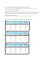
Agilent N6705 DC Power Analyzer Supplemental Characteristics
Supplemental characteristics are not warranted but are descriptions of performance determined either by design or by type testing.
All supplemental characteristics are typical unless otherwise noted.
Arbitrary waveform generator maximum bandwidth
Maximum bandwidth is based on a sine wave into a resistive load and applies to any output current level. In the tables below, THD means
Total Harmonic Distortion, Vp-p means volts peak-to-peak, 3 dB max frequency is the frequency where the output voltage drops to 3 dB below
the programmed value, and 6 dB max frequency is the frequency where the output voltage drops to 6 dB below the programmed value.
N6780 Series 2-quadrant source/measure units
SMU maximum bandwidth is > 10 kHz. Contact Agilent Technologies for more information about SMU bandwidth.
N6750 High-performance autoranging DC power modules and N6760 precision DC power modules
N6751
N6752
3 dB max
frequency
THD at 3 dB
max frequency
0.5 Vp-p
4000 Hz
12.0%
Frequency below
which THD is
less than 1.5%
440 Hz
1 Vp-p
2200 Hz
21.0%
440 Hz
2.5 Vp-p
900 Hz
25.0%
265 Hz
5 Vp-p
500 Hz
27.0%
160 Hz
50 Vp-p
340 Hz
22.0%
25 Hz
3 dB max
frequency
THD at 3 dB
max frequency
Frequency below
which THD is
less than 1.5%
N6754
0.6 Vp-p
3600 Hz
6.0%
2100 Hz
1.2 Vp-p
2600 Hz
10.0%
1280 Hz
3 Vp-p
1700 Hz
17.0%
800 Hz
6 Vp-p
1000 Hz
17.0%
480 Hz
60 Vp-p
340 Hz
22.0%
30 Hz
3 dB max
Frequency
THD at 3 dB
max frequency
0.5 Vp-p
4500 Hz
14.0%
450 Hz
1 Vp-p
3600 Hz
14.0%
450 Hz
2.5 Vp-p
1300 Hz
25.0%
340 Hz
5 Vp-p
600 Hz
25.0%
250 Hz
50 Vp-p
350 Hz
22.0%
30 Hz
N6761
N6762
Frequency below
which THD is
less than 1.5%
21
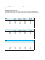
Agilent N6705 DC Power Analyzer Supplemental Characteristics
(Continued)
Supplemental characteristics are not warranted but are descriptions of performance determined either by design or by type testing.
All supplemental characteristics are typical unless otherwise noted.
Arbitrary waveform generator maximum bandwidth
Maximum bandwidth is based on a sine wave into a resistive load and applies to any output current level. In the tables below, THD means
Total Harmonic Distortion, Vp-p means volts peak-to-peak, 3 dB max frequency is the frequency where the output voltage drops to 3 dB below
the programmed value, and 6 dB max frequency is the frequency where the output voltage drops to 6 dB below the programmed value.
N6730 50 W and N6740 100 W basic DC power modules
N6731B
N6741B
3 dB max
frequency
THD at 3 dB
max frequency
0.05 Vp-p
175 Hz
1.0%
260 Hz
3.0%
0.1 Vp-p
125 Hz
1.0%
175 Hz
3.0%
0.25 Vp-p
75 Hz
6.0%
100 Hz
6.0%
0.5 Vp-p
40 Hz
9.0%
55 Hz
9.0%
5 Vp-p
20 Hz
10.0%
37 Hz
10.0%
N6732B
N6742B
6 dB max
frequency
3 dB max
frequency
THD at 3 dB
max frequency
0.08 Vp-p
125 Hz
1.0%
200 Hz
3.0%
0.16 Vp-p
125 Hz
1.0%
180 Hz
3.0%
0.4 Vp-p
75 Hz
6.0%
100 Hz
6.0%
0.8 Vp-p
40 Hz
8.5%
60 Hz
8.5%
8 Vp-p
20 Hz
10.0%
37 Hz
10.0%
N6733B
N6743B
6 dB max
frequency
THD at 6 dB
max frequency
6 dB max
frequency
THD at 6 dB
max frequency
3 dB max
frequency
THD at 3 dB
max frequency
0.2 Vp-p
110 Hz
1.0%
190 Hz
3.0%
0.4 Vp-p
110 Hz
1.0%
160 Hz
3.0%
1 Vp-p
72 Hz
6.0%
95 Hz
6.0%
2 Vp-p
40 Hz
8.0%
55 Hz
8.5%
20 Vp-p
20 Hz
10.0%
37 Hz
10.0%
22
THD at 6 dB
max frequency
Agilent N6705 DC Power Analyzer Supplemental Characteristics
(Continued)
Supplemental characteristics are not warranted but are descriptions of performance determined either by design or by type testing.
All supplemental characteristics are typical unless otherwise noted.
Arbitrary waveform generator maximum bandwidth
Maximum bandwidth is based on a sine wave into a resistive load and applies to any output current level. In the tables below, THD means
Total Harmonic Distortion, Vp-p means volts peak-to-peak, 3 dB max frequency is the frequency where the output voltage drops to 3 dB below
the programmed value, and 6 dB max frequency is the frequency where the output voltage drops to 6 dB below the programmed value.
N6730 50 W and N6740 100 W basic DC power modules (Continued)
N6734B
N6744B
3 dB max
frequency
THD at 3 dB
max frequency
0.35 Vp-p
125 Hz
1.0%
200 Hz
1.0%
0.7 Vp-p
125 Hz
1.0%
175 Hz
3.5%
1.75 Vp-p
72 Hz
6.0%
100 Hz
6.0%
3.5 Vp-p
40 Hz
8.0%
55 Hz
8.5%
35 Vp-p
20 Hz
8.0%
37 Hz
8.5%
N6735B
N6745B
6 dB max
frequency
3 dB max
frequency
THD at 3 dB
max frequency
0.6 Vp-p
100 Hz
1.0%
180 Hz
1.0%
1.2 Vp-p
100 Hz
1.0%
160 Hz
3.0%
3 Vp-p
70 Hz
5.5%
92 Hz
5.5%
6 Vp-p
40 Hz
8.0%
55 Hz
8.0%
60 Vp-p
20 Hz
8.0%
37 Hz
8.0%
N6736B
N6746B
3 dB max
frequency
6 dB max
frequency
THD at 6 dB
max frequency
THD at 3 dB
max frequency
6 dB max
frequency
THD at 6 dB
max frequency
THD at 6 dB
max frequency
1 Vp-p
90 Hz
1.0%
160 Hz
1.5%
2 Vp-p
90 Hz
1.0%
150 Hz
3.0%
5 Vp-p
62 Hz
4.5%
85 Hz
6.0%
10 Vp-p
37 Hz
8.0%
50 Hz
8.0%
100 Vp-p
20 Hz
8.0%
35 Hz
8.0%
23
Agilent N6705 DC Power Analyzer Supplemental Characteristics
(Continued)
Supplemental characteristics are not warranted but are descriptions of performance determined either by design or by type testing.
All supplemental characteristics are typical unless otherwise noted.
Arbitrary waveform generator maximum bandwidth
Maximum bandwidth is based on a sine wave into a resistive load and applies to any output current level. In the tables below, THD means
Total Harmonic Distortion, Vp-p means volts peak-to-peak, 3 dB max frequency is the frequency where the output voltage drops to 3 dB below
the programmed value, and 6 dB max frequency is the frequency where the output voltage drops to 6 dB below the programmed value.
N6770 300 W basic DC power modules
N6773A
3 dB max
frequency
THD at 3 dB
max frequency
0.2 Vp-p
125 Hz
1.5%
210 Hz
4.0%
0.4 Vp-p
125 Hz
1.5%
180 Hz
4.0%
1 Vp-p
75 Hz
6.0%
95 Hz
6.0%
2 Vp-p
42 Hz
9.0%
60 Hz
9.0%
20 Vp-p
20 Hz
10.0%
37 Hz
10.0%
N6774A
3 dB max
frequency
6 dB max
frequency
THD at 3 dB
max frequency
6 dB max
frequency
THD at 6 dB
max frequency
THD at 6 dB
max frequency
0.35 Vp-p
125 Hz
1.0%
200 Hz
1.0%
0.7 Vp-p
125 Hz
1.0%
160 Hz
3.0%
1.75 Vp-p
75 Hz
6.0%
95 Hz
6.0%
3.5 Vp-p
40 Hz
8.5%
55 Hz
8.5%
35 Vp-p
20 Hz
10.0%
37 Hz
10.0%
N6775A
3 dB max
frequency
THD at 3 dB
max frequency
0.6 Vp-p
120 Hz
1.0%
200 Hz
1.2 Vp-p
120 Hz
1.0%
160 Hz
3.0%
3 Vp-p
70 Hz
5.0%
95 Hz
6.0%
6 Vp-p
40 Hz
8.5%
55 Hz
8.5%
60 Vp-p
20 Hz
10.0%
35 Hz
10.0%
N6776A
3 dB max
frequency
6 dB max
frequency
THD at 3 dB
max frequency
6 dB max
frequency
THD at 6 dB
max frequency
1.0%
THD at 6 dB
max frequency
1 Vp-p
75 Hz
1.0%
160 Hz
1.0%
2 Vp-p
75 Hz
1.0%
150 Hz
3.0%
5 Vp-p
55 Hz
4.0%
75 Hz
6.0%
10 Vp-p
35 Hz
8.0%
45 Hz
8.0%
100 Vp-p
N/A
N/A
35 Hz
8.0%
24
Agilent N6705A and N6705B DC Power Analyzer Mainframes
N6705A, N6705B
Maximum total
output power
N6705A, N6705B
(= Sum of total
module output power)
Command
processing time
Protection response
characteristics
Digital control
characteristics
From receipt of command to start
of the output change
600 W
when operating from 100 – 240 VAC input
≤ 1 ms
INH input
5 µs from receipt of inhibit to start of shutdown
Fault on coupled outputs
< 10 µs (from receipt of fault to start of shutdown)
Maximum voltage ratings
16.5 VDC/- 5 VDC between pins (pin 8 is internally connected to chassis ground).
Pins 1 and 2 as FLT output
Maximum low-level output voltage = 0.5 V @ 4 mA
Maximum low-level sink current = 4 mA
Typical high-level leakage current = 0.14 mA @ 16.5 VDC
Pins 1 - 7 as digital/trigger outputs
(pin 8 = common)
Maximum low-level output voltage = 0.5 V @ 4 mA; 1 V @ 50 mA; 1.75 V @ 100 mA
Maximum low-level sink current = 100 mA
Typical high-level leakage current = 0.12 mA @ 16.5 VDC
Pins 1 - 7 as digital/trigger inputs and
pin 3 as INH input
(pin 8 = common)
Maximum low-level input voltage = 0.8 V
Minimum high-level input voltage = 2 V
Typical low-level current = 2 mA @ 0 V (internal 2.2 k pull-up)
Typical high-level leakage current = 0.12 mA @ 16.5 VDC
Trig out BNC
Maximum low-level output voltage = 0.8 V @ 1.25 mA
Minimum high-level output voltage = 4.0 V @ 1.25 mA
Typical output pulse width = 8 µs
Trig in BNC
(with internal 100 Kohm pull-up)
Maximum low-level input voltage = 1.3 V
Minimum high-level input voltage = 2.7 V
Minimum input pulse width = 2 µs
Interface capabilities
GPIB:
SCPI - 1993, IEEE 488.2 compliant interface
LXI compliance
Class C
USB 2.0
Requires Agilent IO Library version M.01.01 and up, or 14.0 and up
10/100 LAN
Requires Agilent IO Library version L.01.01 and up, or 14.0 and up
Built-in web server
Requires Internet Explorer 5+ or Netscape 6.2+
Environmental conditions
Operating environment
Indoor use, installation category II (for AC input), pollution degree 2
Temperature range
0°C to 55°C (current is derated 1% per °C above 40°C ambient temperature)
Relative humidity
Up to 95%
Altitude
Up to 2000 meters
Storage temperature
-30°C to 70°C
LED statement
Any LEDs used in this product are Class 1 LEDs as per IEC 825-1
25
Agilent N6705A and N6705B DC Power Analyzer Mainframes
(Continued)
N6705A, N6705B
Regulatory
compliance
EMC
Complies with the European EMC directive for Class A test and
measurement products.
Complies with the Australian standard and carries the C-Tick mark.
This ISM device complies with Canadian ICES-001.
Cet appareil ISM est conforme à la norme NMB-001 du Canada.
Electrostatic discharges greater than 1 kV near the I/O connectors may cause
the unit to reset and require operator intervention.
Acoustic noise
declaration
Safety
Complies with the European Low Voltage Directive and carries the CE-marking.
This product also complies with the US and Canadian safety standards for test
and measurement products.
This statement is provided to
comply with the requirements
of the German Sound Emission
Directive, from 18 January 1991.
Sound pressure Lp < 70 dB(A),
At operator position and normal operation, according to EN 27779 (Type Test).
Schalldruckpegel Lp <70 dB(A)
Am arbeitsplatz und normaler betrieb, nach EN 27779 (Typprüfung).
Maximum rating
No output terminal may be more than 240 VDC from any other terminal or chassis ground.
Output terminal
isolation
AC input
Nominal input ratings
100 VAC – 240 VAC; 50/60 Hz/400 Hz
Input range
86 VAC – 264 VAC
Power consumption
1500 VA typical
Fuse
Internal fuse (not customer accessible)
Weight
N6705 with 4 installed modules
Net: 17.3 kg; 38 lbs.
Single-wide power module
Net: 1.23 kg; 2.71 lbs
Double-wide power module
Net: 2.18 kg; 4.8 lbs
26
Autoranging Characteristic
Voltage
Voltage
Precision Outputs
Autoranging 50 W Output
50 V
50 V
50 W Curve
33 V
10 V
0
1A
5A
Current
0
Voltage
Voltage
Voltage
N6754A Autoranging
300 W Output
Autoranging 100 W Output
60 V
50 V
100 W Curve
300 W Curve
6V
15 V
2A
8.33 A 10 A
N6753A Autoranging
300 W Output
20 V
300 W Curve
12 V
8.5 V
0
Current
1 A 1.5 A – 50 W output
2 A 3 A – 100 W output
Current
0
5A
20 A
Current
0
15 A
50 A
Outline Diagram
272.6 mm
10.733 in
425.6 mm
16.756 in
16.9 mm
23.5 mm
0.663 in
0.923 in
177.0 mm
6.968 in
17.7 mm
0.697 in
27
Current
Ordering Information
The DC power analyzer system
is available 2 ways:
(1) You can order an N6705B mainframe
and various modules as separate
products. (See steps below.) Each
item will arrive in a separate box
such that you can assemble the analyzer yourself when you need to.
(2) You can order an N6715B system,
which is a build-to-order DC power
analyzer system that is shipped as
a fully assembled multiple-output
power supply. (See pages 30 and 31
for N6715B ordering information.)
When ordering the DC power analyzer
as a mainframe and modules, follow
these steps:
Step 1:
Select the appropriate documentation
and line cord options.
Step 2:
Order 1 to 4 modules (see next page).
If the sum of the power of the modules
exceeds the available output power
rating on the mainframe, see page 12
for an explanation of Agilent’s power
management capability. Note that each
mainframe has 4 module slots to hold
modules. Each module occupies one
module slot, except for the N6754A,
which occupies 2 module slots per
module.
Mainframe
N6705B
DC power analyzer mainframe
Holds 1 to 4 modules.
Total available output power = 600 W.
Available options to the N6705B mainframe
908
Rack mount kit
AKY
Delete front/rear USB
This option removes all USB capability from the DC power analyzer.
Both the front panel USB port and the rear panel USB port are removed.
055
Delete Datalogger
This option disables the Datalogger functionality in the DC power analyzer firmware.
The DC power analyzer hardware is unchanged. To enable the Datalogger functionality
at a later time, order the N6705U upgrade kit.
ABA
Full documentation on CD-ROM and printed Users Guide
0B0
Full documentation on CD-ROM only; no printed documentation package
900
Power Cord, United Kingdom, P/N 8120-1351
901
Power Cord, Australia, New Zealand, P/N 8120-1369
902
Power Cord, Europe, Korea, P/N 8120-1689
903
Power Cord, USA, Canada, 120 V, P/N 8120-4383
904
Power Cord, USA, Canada, 240 V, P/N 8120-0698
906
Power Cord, Switzerland, P/N 8120-2104
912
Power Cord, Denmark, P/N 8120-2956
917
Power Cord, South Africa, India, P/N 8120-4211
918
Power Cord, Japan, 100 V, P/N 8120-5342
919
Power Cord, Israel, P/N 8120-6800
920
Power Cord, Argentina, P/N 8120-6869
921
Power Cord, Chile, P/N 8120-6980
922
Power Cord, China, P/N 8120-8376
927
Power Cord, Thailand, Brazil, P/N 8120-8871
28
Ordering Information
Modules
Order 1 to 4 modules to be installed in
each N6705 DC power analyzer mainframe. (To order modules as part of the
N6715 build-to-order systems, see page
31). If the sum of the power of the modules exceeds the available output power
rating on the mainframe, see page 12
for an explanation of Agilent’s power
management capability.
Modules
N6730 50 W
DC power modules
N6740 100 W
DC power modules
You can individually specify each option
for each module. For example, you
can order one module with Option 761
Output Disconnect Relays while the
remaining modules have no relay option.
N6750 High-performance,
autoranging DC power
modules
As your needs change and you want to
change configuration or add more modules to the existing N6705 mainframe, use
this ordering information to order the
required modules.
N6760 precision
DC power modules
N6770 300 W
DC power modules
N6780 Series
2-quadrant SMUs
N6731B
5 V, 10 A, 50 W DC Power Module
N6732B
8 V, 6.25 A, 50 W DC Power Module
N6733B
20 V, 2.5 A, 50 W DC Power Module
N6734B
35 V, 1.5 A, 50 W DC Power Module
N6735B
60 V, 0.8 A, 50 W DC Power Module
N6736B
100 V, 0.5 A, 50 W DC Power Module
N6741B
5 V, 20 A, 100 W DC Power Module
N6742B
8 V, 12.5 A, 100 W DC Power Module
N6743B
20 V, 5 A, 100 W DC Power Module
N6744B
35 V, 3 A, 100 W DC Power Module
N6745B
60 V, 1.6 A, 100 W DC Power Module
N6746B
100 V, 1 A, 100 W DC Power Module
N6751A
50 V, 5 A, 50 W High-Performance
Autoranging DC Power Module
N6752A
50 V, 10 A, 100 W High-Performance
Autoranging DC Power Module
N6753A
20 V, 50 A, 300 W High-Performance
Autoranging DC Power Module
(occupies 2 module slots in the mainframe)
N6754A
60 V, 20 A, 300 W High-Performance
Autoranging DC Power Module
(occupies 2 module slots in the mainframe)
N6761A
50 V, 1.5 A, 50 W Precision DC Power Module
N6762A
50 V, 3 A, 100 W Precision DC Power Module
N6773A
20 V, 15 A, 300 W DC Power Module
N6774A
35 V, 8.5 A, 300 W DC Power Module
N6775A
60 V, 5 A, 300 W DC Power Module
N6776A
100 V, 3 A, 300 W DC Power Module
N6781A
20 V, ± 3 A, 20 W 2-Quadrant DC Power Module
for Battery Drain Analysis
N6782A
20 V, ± 3 A, 20 W 2-Quadrant DC Power Module
for Functional Test
Available options to DC power modules
N6731B-N6736B
50 W DC
power modules
N6741B-N6746B N6751A-N6752A
100 W DC
high-performance
power modules autoranging DC
power modules
N6754A
N6761A-N6762A N6773A-N6776A N6781A300 W highprecision DC
300 W DC power N6782A
performance
power modules modules
SMUs
autoranging DC
power module
Output disconnect relays
761
761
761
761
761
Standard
Output disconnect and polarity reversal relays
760
760 (see note 1, 2) Not available
761
760
Not available
760 (see note 2)
Not available
Large size FPGA Installed
Not available,
not required
Not available,
not required
Not available,
not required
Not available,
not required
Not available,
not required
Not available,
not required
Commercial calibration with test results data
UK6
UK6
UK6
UK6
UK6
UK6
UK6
ISO 17025 Cal certificate
1A7
1A7
1A7
1A7
1A7
1A7
Not available
LGA (Required,
see note 3)
1 Option 760 is not available on N6741B.
2 When Option 760 is installed in N6742B or N6773A, the maximum output current is limited to 10 A.
3 You must order Option LGA on N6751A and N6752A modules.
4 High Speed Test Extensions (HSTE) is not needed on modules for use in the DC power analyzer.
29
Ordering Information
N6715B build-to-order systems
To purchase a DC power analyzer
system, order a N6715B. This model
number is a build-to-order system that is
shipped as a fully tested and assembled
instrument. Each system consists of
one mainframe plus optionally 1 to 4
modules. Each mainframe has 4 module slots to hold modules. Each module
occupies one module slot, except for
the N6754A, which occupies 2 module
slots per module. To specify which
modules you want installed in the system, the modules are ordered as options
to the system model number. You must
order at least 1 module.
If the sum of the power of the modules
exceeds the available output power
rating on the mainframe, see page 12
for an explanation of Agilent’s power
management capability.
If you prefer to purchase a DC power
analyzer mainframe and modules as
separate pieces, see page 28.
Build-to-order system
N6715B System
Build-to-order DC power analyzer system
Consists of 1 N6705 mainframe with total available power of 600 W.
Available options to the N6715B System
908
Rack mount kit
AKY
Delete front/rear USB
This option removes all USB capability from the DC power analyzer.
Both the front panel USB port and the rear panel USB port are removed.
055
Delete Datalogger
This option disables the Datalogger functionality in the DC power analyzer
firmware. The DC power analyzer hardware is unchanged. To enable the
Datalogger functionality at a later time, order the N6705U upgrade kit.
ABA
Full documentation on CD-ROM and printed Users Guide
0B0
Full documentation on CD-ROM only; no printed documentation package
900
Power Cord, United Kingdom, P/N 8120-1351
901
Power Cord, Australia, New Zealand, P/N 8120-1369
902
Power Cord, Europe, Korea, P/N 8120-1689
903
Power Cord, USA, Canada, 120 V, P/N 8120-4383
904
Power Cord, USA, Canada, 240 V, P/N 8120-0698
906
Power Cord, Switzerland, P/N 8120-2104
912
Power Cord, Denmark, P/N 8120-2956
917
Power Cord, South Africa, India, P/N 8120-4211
918
Power Cord, Japan, 100 V, P/N 8120-5342
919
Power Cord, Israel, P/N 8120-6800
920
Power Cord, Argentina, P/N 8120-6869
921
Power Cord, Chile, P/N 8120-6980
922
Power Cord, China, P/N 8120-8376
927
Power Cord, Thailand, Brazil, P/N 8120-8871
30
Ordering Information
Modules as options to N6715B
To order 1 to 4 modules as options to
an N6715B, specify its model number,
followed by “–ATO.” For example, to
order an N6731B as an option to the
N6715B, you would specify “N6731B–
ATO” as the option. (To order modules
as separate products, see page 29.) If
the sum of the power of the modules
exceeds the available output power
rating on the mainframe, see page 12
for an explanation of Agilent’s power
management capability.
Module options for N6710B, N6711A and N6712A systems
N6730 50 W
DC power modules
N6740 100 W
DC power modules
You can individually specify each option
for each module. For example, you can
order one module with Option 761
Output Disconnect Relays while the
remaining modules have no relay option.
N6750 High-performance
autoranging DC
power Modules
N6760 Precision
DC power modules
N6770 300 W
DC power modules
N6780 Series
2-quadrant SMUs
N6731B–ATO
5 V, 10 A, 50 W DC Power Module
N6732B–ATO
8 V, 6.25 A, 50 W DC Power Module
N6733B–ATO
20 V, 2.5 A, 50 W DC Power Module
N6734B–ATO
35 V, 1.5 A, 50 W DC Power Module
N6735B–ATO
60 V, 0.8 A, 50 W DC Power Module
N6736B–ATO
100 V, 0.5 A, 50 W DC Power Module
N6741B–ATO
5 V, 20 A, 100 W DC Power Module
N6742B–ATO
8 V, 12.5 A, 100 W DC Power Module
N6743B–ATO
20 V, 5 A, 100 W DC Power Module
N6744B–ATO
35 V, 3 A, 100 W DC Power Module
N6745B–ATO
60 V, 1.6 A, 100 W DC Power Module
N6746B–ATO
100 V, 1 A, 100 W DC Power Module
N6751A–ATO
50 V, 5 A, 50 W High-Performance
Autoranging DC Power Module
N6752A–ATO
50 V, 10 A, 100 W High-Performance
Autoranging DC Power Module
N6753A-ATO
20 V, 50 A, 300 W High-Performance
Autoranging DC Power Module
(occupies 2 module slots in the mainframe)
N6754A-ATO
60 V, 20 A, 300 W High-Performance
Autoranging DC Power Module
(occupies 2 module slots in the mainframe)
N6761A–ATO
50 V, 1.5 A, 50 W Precision DC Power Module
N6762A–ATO
50 V, 3 A, 100 W Precision DC Power Module
N6773A–ATO
20 V, 15 A, 300 W DC Power Module
N6774A–ATO
35 V, 8.5 A, 300 W DC Power Module
N6775A–ATO
60 V, 5 A, 300 W DC Power Module
N6776A–ATO
100 V, 3 A, 300 W DC Power Module
N6781A–ATO
20 V, ± 3 A, 20 W 2-Quadrant DC Power Module
for Battery Drain Analysis
N6782A–ATO
20 V, ± 3 A, 20 W 2-Quadrant DC Power Module
for Functional Test
Available options to N6700 modules
N6731B-ATO
to N6736B-ATO
50 W DC power
modules
N6741B-ATO
to N6746B-ATO
100 W DC power
modules
N6751A-ATO
to N6752A-ATO
High-performance
autoranging DC
power modules
N6753A-ATO
to N6754A-ATO
300 W Highperformance
autoranging DC
power modules
N6761A-ATO
to N6762A-ATO
precision DC
power modules
N6773A-ATO
N6781A-ATO
to N6776A-ATO N6782A-ATO
300 W DC power SMUs
modules
Output disconnect relays
761
761
761
761
761
761
Output disconnect and polarity reversal relays
760
760 (see note 1, 2) Not available
760
Not available
760 (see note 2) Not available
High speed test extensions (HSTE)
Not available
Not available
054
054
Standard
Not available
Standard
Large size FPGA installed
Not available,
not required
Not available,
not required
LGA (Required,
see note 3)
Not available,
not required
Not available,
not required
Not available,
not required
Not available,
not required
Commercial calibration with test results data
UK6
UK6
UK6
UK6
UK6
UK6
UK6
ISO 17025 Cal certificate
1A7
1A7
1A7
1A7
1A7
1A7
Not available
1 Option 760 is not available on N6741B-ATO.
2 When Option 760 is installed in N6742B-ATO or N6773A-ATO, the maximum output current is limited to 10 A.
3 You must order Option LGA on N6751A and N6752A modules. Option LGA adds a large size FGPA to the module. Option LGA is required to
support the Output Sequencing between multiple mainframes. Option LGA will also allow for future expansion for additional firmware features.
31
Standard
Remove all doubt
Agilent Email U
www.agilent.com/find/emailupdates
Get the latest information on the
products and applications you select.
Agilent Channel Partners
www.agilent.com/find/channelpartners
Get the best of both worlds: Agilent’s
measurement expertise and product
breadth, combined with channel
partner convenience.
www.lxistandard.org
LXI is the LAN-based successor to
GPIB, providing faster, more efficient
connectivity. Agilent is a founding
member of the LXI consortium.
Our repair and calibration services
will get your equipment back to
you, performing like new, when
promised. You will get full value out
of your Agilent equipment throughout its lifetime. Your equipment
will be serviced by Agilent-trained
technicians using the latest factory
calibration procedures, automated
repair diagnostics and genuine parts. You
will always have the utmost confidence
in your measurements. For information
regarding self maintenance of this
product, please contact your Agilent
office.
Agilent offers a wide range of additional
expert test and measurement services
for your equipment, including initial
start-up assistance, onsite education
and training, as well as design, system
integration, and project management.
For more information on repair and
calibration services, go to:
www.agilent.com/find/removealldoubt
Need a power solution for ATE?
The new Agilent N6700 Modular Power Analyzer is small, flexible, and fast
• Ideal for ATE
systems in R&D,
design validation,
and manufacturing
• Small size: up to 4 outputs in 1U of rack space
• Flexible, modular system: Can mix and match power levels and performance
levels to optimize investment
• Uses same modules as N6705 DC Power Analyzers
• Fast command processing times to improve throughput
www.agilent.com
www.agilent.com/find/N6700
For more information on Agilent
Technologies’ products, applications or
services, please contact your local Agilent
office. The complete list is available at:
www.agilent.com/find/contactus
Americas
Canada
Latin America
United States
(877) 894 4414
305 269 7500
(800) 829 4444
Asia Pacific
Australia
China
Hong Kong
India
Japan
Korea
Malaysia
Singapore
Taiwan
Thailand
1 800 629 485
800 810 0189
800 938 693
1 800 112 929
0120 (421) 345
080 769 0800
1 800 888 848
1 800 375 8100
0800 047 866
1 800 226 008
Europe & Middle East
Austria
43 (0) 1 360 277 1571
Belgium
32 (0) 2 404 93 40
Denmark
45 70 13 15 15
Finland
358 (0) 10 855 2100
France
0825 010 700*
*0.125 €/minute
Germany
49 (0) 7031 464 6333
Ireland
1890 924 204
Israel
972-3-9288-504/544
Italy
39 02 92 60 8484
Netherlands
31 (0) 20 547 2111
Spain
34 (91) 631 3300
Sweden
0200-88 22 55
Switzerland
0800 80 53 53
United Kingdom 44 (0) 118 9276201
Other European Countries:
www.agilent.com/find/contactus
• Connect via GPIB, LAN, or USB
Revised: October 1, 2009
• Fully compliant to LXI Class C specification
Product specifications and descriptions
in this document subject to change without
notice.
Complete specifications can be found in the N6700 Modular Power System
Data Sheet, publication 5958-1411EN. For more information, go to
www.agilent.com/find/N6700
© Agilent Technologies, Inc. 2011
Printed in USA, March 22, 2011
5989-6319EN