1
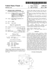
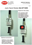
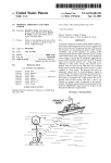
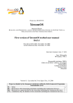
United States Patent [19]
[11]
4,419,056
Ege
[45]
Dec. 6, 1983
[54] BACK-UP FOR HIGH VOLTAGE CABLE
PRESSURIZING SYSTEM
[75] Inventor:
Sigmund Ege, Oslo, Norway
[73] Assignee:
International Standard Electric
2,817,396 12/1957
Booth ................................ .. 417/428
3,388,207
6/1968
Lansch ..
137/567
3,782,863
1/1974
Rupp ...... ..
417/393
4,080,107 3/1978 Ferrentino
417/273
4,341,508
7/1982
Rambin, Jr. ....................... .. 417/426
Primary Examiner—Carlton R. Croyle
Corporation, New York, NY.
[21] Appl. No: 285,700
Assistant Examiner—Paul F. Neils
Attorney, Agent, or Firm-John T. O’Halloran; Alfred
[22] Filed:
C. Hill
[30]
Jul. 22, 1981
Aug. 4, 1980 [NO]
[51]
[52]
[57]
Foreign Application Priority Data
Norway ............................... ., 802327
Int. Cl.3 ...................... .. F04B 23/04; F04B 43/06
U.S. Cl. .................................... .. 417/426; 417/53;
417/393; 92/5 R
[58]
Field of Search ............... .. 417/63, 374, 425, 426,
417/434, 435, 53, 393, 395; 92/5 R; 91/1, 51;
60/571
[56]
References Cited
ABSTRACT
A back-up system is provided for a pumping plant or a
pressure reservoir system used to maintain insulating oil
under pressure in high voltage submarine power cables
which includes a gas driven membrane pump to insure
a small outflow of oil at a rupture point in the power
cable to prevent water from penetrating the cable. The
proper operation of the membrane pump is insured by
introducing degasi?ed oil at the drive side of the pump
during the stand-by and test modes of operation of the
back-up system.
U.S. PATENT DOCUMENTS
1,627,257
5/1927
Stevens ............................... .. 417/63
/O|LOUTLET
CHAMBER 5f
DIAPHRAGM/J
PUMP 5b
[j_0|L FILLED
z,
POWER CABLE
/
c
20 Claims, 19 Drawing Figures
US. Patent
Dec. 6, 1983
1,
$10K
FILLED
POWER CABLE
Sheet 1 of5
4,419,056
U.S. Patent
Dec. 6, 1983
2E
Sheet 2 of5
“i i;
ll
_2_27
4,419,056
27
22.
U.S. Patent
Dec. 6, 1983
Sheet 3 of5
Fig .17.
4,419,056
U.S. Patent
Dec. 6, 1983
Sheet4 of5
4,419,056
U.S. Patent
Dec. 6, 1983
Sheet 5 of5
4,419,056
1
4,419,056
BACK-UP FOR HIGH VOLTAGE CABLE
PRESSURIZING SYSTEM
BACKGROUND OF THE INVENTION
Paper and oil insulated high voltage power cables
rely on maintaining the insulating oil under pressure for
the proper functioning. In the case of the so-called Pipe
Type ‘Cable (three insulated conductors pulled into a
common steel pipe) the pressure is normally maintained‘
by a pump drawing oil from an oil tank. The so-called
Self Contained Cable is normally kept under pressure
by means of static oil reservoirs, although in certain
cases a “Pumping Plant” may also be used for this type
2
moisture to permeate through the membrane to the
cable oil on the other side.
SUMMARY OF THE INVENTION
The main object of the present invention is to over
come the disadvantage of the previously known back
up systems.
The present invention overcomes the disadvantages
of known back-up systems by comprising at least one
diaphragm pump for pumping cable oil from an oil
reservoir to the cable core in case of rupture of the cable
sheath causing oil leaks and means for providing that
the drive or gas side and the inlet/outlet or suction side
of the diaphragm of the pump are subjected to oil at
of cable, particularly in the case of long submarine 15 least during the stand-by mode of the pump.
By ?lling the gas side of the membranes with degasi
crossings.
?ed cable oil, this part of the pump may be maintained
One reason why pumping plants are being used also
under a positive pressure (by means of the same type of
for Self Contained Submarine Cables is that with this
pressure reservoir which is used on the cable, or—in the
system it is reasonably inexpensive to store a large quan
tity of oil in case the cable should become ruptured, so
case of a system with pumping plant—from the electric
that one might prevent water from entering the cable by
pump which maintains pressure on the cable) until the
creating a certain small out?ow of oil at the rupture
pump is called upon to provide additional oil to the
point. The pumping plant is, however, dependent on
cable (for instance due to a leak developing) or—in the
supply of electricity. The oil reservoir system does not
case of a system with pumping plant—to take over from
require electricity, but the cost of providing extra oil 25 the electric pump in case of power failure. At this time
capacity for a possible cable rupture becomes prohibi
the oil on the drive side of the membrane will, of course,
tive.
be replaced by the driving gas, but this condition will
For pumping plants, pumps relying on means other
only persist until such a time as the leak in the cable has
than electric motors are known to have been used as a
been stopped (or the cable end capped in case of a com
back-up in case of power failure. The back-up pump 30 plete severance) and the cable again can be kept under
may have been driven by an air motor, fed either with
pressure by the reservoirs. This time period will be
air or nitrogen stored under high pressure in gas cylin
fairly short, and moisture and gas will not have time to
ders.
permeate the membrane to any detrimental degree.
If a suitable system could be developed which could
In preparing the pump for “stand-by,” vacuum can be
35
act as a back-up for a pumping plant, such a system
pulled on the whole pump (both on the oil side and the
ought to be suitable also as a back-up for pressure reser
gas side of the membranes, including the valve system
voirs in case a leak should develop in the cable system.
Unfortunately the oil in a Self Contained Cable must
be virtually completely free from moisture and gas in
which makes the rod connecting the two membranes
reciprocate). While the pump is still under vacuum it is
order to function properly as an insulation together 40 ?lled with degasi?ed oil.
One added advantage of the invention is that all the
with the paper. For this reason it is, for instance, not
critical
parts (in particular the valve system) will be
permissible to store such oil under a “blanket” of nitro
kept in good condition by the oil, so that one may be
gen, such as is normally the case for a pipe-type cable
certain that the pump really will work after having been
pumping plant. For this reason it is known to use so
called “canned” motors to drive the pump in pumping 45 standing idle, maybe for years.
When the back-up system has performed its function,
plants for this type of cable. Use of these hermetic mo
the pump can again be evacuated and ?lled with degasi
tors excludes the need for a rotating seal on the shaft
?ed oil. This could conveniently be done at the time
between the motor and the pump. Such a shaftseal is
that the oil storage tank is being evacuated to be re?lled
particularly undesirable in the case of a pump which is
with degasi?ed oil.
to stand as a back-up, maybe for several years, before it
According to one embodiment of the invention,
is called upon to pump oil.
which is particularly convenient when the invention is
Hermetic motor-pump combinations for air driven
used in connection with a standard pumping plant, it is
motors without a rotating seal do not exist. The pumps
possible to make a periodic check on the functioning of
which come closest to being “hermetic” are those using
the diaphragm or membrane principle. One such pump 55 the “gas-driven” pump without introducing gas into the
gas chamber of the pump. This is accomplished by
(marketed by THE WARREN RUPP CO. Mans?eld,
driving the pump by means of oil under pressure sup
Ohio under the trade name “Sand Piper” Pump Model
No. SAI-A or SBl-A) utilizing two membranes con
nected by a rod and with a driving gas in contact with
the “rod-side” of the two membranes, seems particu
larly well suited for the purpose. A diaphragm or mem
plied by the electric oil pump which normally applies
pressure to the cable system. Such a test will ?rst of all
prove that the pump really will operate should it be
asked to take over the pumping action, and the oil
which during stand-by has been sitting in the “oil cham
brane pump of this type is shown in Operating Instruc
ber”
of the pump during this time, could be checked for
tions, Service Manual and Repair Parts List, issued as
gas content and power factor. With oil on both sides of
Form No. SPL-2/77R by The Warren Rupp Co. and
fully disclosed in US. Pat. No. 3,782,863, whose disclo 65 the membrane it will also be possible to make sensitive
tests for possible cracks in the membrane by valving off
sure is incorporated herein by reference. The only dis
the two sides of the membrane and monitoring the dif
advantage is that it utilizes a membrane which is not
ferential pressure.
made of metal, and therefore, in time, will allow gas and
3
4,419,056
The above test could also be made on the back-up
system for cables supplied with pressure oil reservoirs,
but in this case a separate degasi?er and an oil pump will
have to be used to perform the test.
According to one embodiment of the invention the
back-up system is mounted on a skid containing all the
required units such as storage tank, pressure reservoir,
pump and gas bottles. Such a back-up may be evacuated
and ?lled with treated oil at the factory, shipped to site
4
FIGS. 17-19 show three modes of operation of the
arrangement of FIG. 16.
DETAILED DESCRIPTION OF THE
INVENTION
In FIG. 1 only three elements of a standard pumping
plant have been included, namely, an oil storage tank 1,
an electrical pump 2 and a check valve 3 which pre
pump with a metallic membrane is being used, particu
vents oil from returning to the tank when the pump is
not running. The oil ducts of the oil ?lled cables are
connected to the pumping plant at 4.
In FIG. 2 is given the legend of the valves shown in
FIG. 1 (and also in FIG. 6). A illustrates a manually
larly if one should require that the pump should be
operated valve, B illustrates an electrically operated
started up occasionally in order to make sure that it
really will pump effectively if called upon to do so. If
the “gas side” of the membrane, it may have serious
consequences to the cable if a crack should develop in
the membrane, since the gas immediately will enter the
valve, and C illustrates a so~called check valve allowing
fluid ?ow in the direction of the arrow only.
Turning now back to FIG. 1, the standard pumping
plant has been provided with a back-up system consist
ing mainly of a membrane pump 5, like that described
above under the heading “Background of the Inven
cable. With the present invention the danger is elimi
tion” marketed by The Warren Rupp Company under
and hooked up to the existing pressurizing system either
of the reservoir or the pumping plant type. The inven
tion may be used to advantage even in the case where a
such a test were to be made with gas rather than oil on
nated since we have degasi?ed oil on both sides of the
the trade name “Sand Piper” Pump Model No. SAl-A
membrane. It is true that gas could still come through a
or SBl-A utilizing two membranes 5a and 512 connected
broken membrane if the back-up system should ever be
by a rod 5c and having a driving gas in contact with the
called upon to maintain pressure on the cable, but at this 25 “rod-side” of the two membranes 5:: and 5b in a ?rst
time the power will have been shut off the cable, and
chamber 5d, a suction input a terminating in a second oil
the introduction of dry nitrogen is therefore not so
inlet chamber 50 and an oil outlet terminating in a third
serious. The gas will not cause an electric breakdown of
or oil outlet chamber 5}‘. The driving gas is provided by
the cable and may be removed by subsequent treatment
a battery of gas bottles 6 via a pressure reducing valve
of the cable oil prior to reenergizing the cable.
7. The inlet and outlet of the “rod-side” or "gas side” of
An alternative solution to the problem outlined above
the pump are indicated by b and d, respectively, while
is to introduce an additional diaphragm type pump, so
a represents the oil suction side and c the oil outlet. The
that the drive side of the main pump is always operated
by degasi?ed oil supplied from the additional pump.
The additional pump may be operated during its test
and operation mode by pressurized gas or air. While the
possibility exists with the additional pump that its dia
phragm may rupture and gas or air may be introduced
back-up system also includes three electrically operated
valves 8, 9 and 10 (these valves are operated by DC
current from a stand-by battery), one manually operated
valve 11 (apart from those connected directly to the gas
bottles 6), and two check valves 12, 13.
The pumping/back-up system has three modes of
into the oil system on its pump side, the risk of transfer
ring deteriorated oil into the pump side of the main
pump is negligible, because the oil on the pump side of
the additional pump and on the drive side of the main
operation mode. In order to give a clear understanding
of the various modes of operation, the state of the valves
is given in the table below where O=open valve,
pump is frequently degasi?ed.
C=closed valve.
BRIEF DESCRIPTION OF THE DRAWINGS
To give a better understanding of the invention, two
examples of its application will be given below, with
reference to the accompanying drawings, in which
FIG. 1 shows the invention used in conjunction with
a pumping plant,
FIG. 2 shows a legend of valves,
FIGS. 3-5 schematically illustrate three modes of
operation of the arrangement of FIG. 1,
FIG. 6 shows how a back-up may be provided for a
cable installation using pressure reservoirs to maintain
operation: a stand-by mode, a test mode and a back-up
'
Mode/Valve No.
Stand-by
Test
Operation
0w0
0\0
050
CO
In the stand-by mode which is also schematically
illustrated in FIG. 3, the membrane pump 5 is kept full
of oil on both sides of the membrane. On the suction
side a the oil is maintained at a pressure equivalent to
the head of oil in the storage tank (this tank being kept
pressure on the cable,
under vacuum), while the oil on the “gas side” of the
FIGS. 7-10 schematically illustrate four modes of
operation of the arrangement of FIG. 6,
provided by the electrical pump 2 for the cable at 4.
pump will be maintained under the same pressure as that
FIG. 11 shows how the back-up system may be
In order to test that the membrane pump 5 is opera
mounted on a skid for pre-fabrication and transporta
ble, without introducing gas into the pump, all valves
but valve 9 are opened. (Valve 11 opened slightly only).
Oil will now ?ow from the tank 1, via the electrical
tion to site,
FIG. 12 schematically illustrates a back-up system for
pump 2 and valve 10 to operate the membrane pump 5
a pumping plant, employing two diaphragm pumps,
because the outlet (1 is opened by the open valve 8. As
FIGS. 13-15 show the three modes of operation of
65 a result the pump 5 will pump oil from its a side to its c
the arrangement of FIG. 12,
side, the pumped oil being drained through valve 11.
FIG. 16 schematically illustrates the two diaphragm
pump solution in connection with pressure reservoir
The drained oil from valve 11 as well as oil exhausted
plant, and
through valve 8 should be tested for deteriorations to
4,419,056
5
6
obtain indication of the condition of the back-up system.
The drained oil should, if necessary, be degasi?ed and
portable source of degasi?ed oil 27 will have to be
brought in and connected to valve 26. The test may be
pumped back to the tank 1. The test mode is also illus
performed by opening valves 26 and 8 (after ?rst having
closed valves 21 and 25) sothat the supply of degasi?ed
trated in; FIG. 4.
'
I
_
i
If the electric power should fail so that the electrical
pump 2 is unable to maintain therequired pressure in
the cable at 4, valve 10 will be switched from open to
closed and thereafter valves 8 and 9 vfromfclosed to
open. In thismode, which is illustrated in FIG._5, the
gas ‘which is supplied from the gas bottle battery 6_, will
?rst force the stand-by oil ,within the pump 5 out
through valve 8 while operating the pump 5, and ?nally
oil operates the pump. Oil from the tank 22 is exhausted
through valve 11.as in the case of FIG. 1, and the oil on
thea/c-side of the pump 5 can be tested for deteriora
tions. Also the oil drained at pump outlet d should be
checked for deteriorations.
.
-'
-
.If the cable should start leaking oil as a result of eXter
nal mechanical damage, or for other reasons, the pres
sure reservoirs 20 will feed additional oil to the cable at
operate the pump '5 on gas as intended. By operation of
4, whereby the pressure will gradually decrease. When the pump 5, oil will be supplied from the tank 1 to the
the pressure approaches a critical low limit, as sensed by
cable at 4.
'
15 a pressure switch (not shown), valve 25 will be closed
When‘ reinstating the stand-by mode after repair of a
?rst, and valves 8 and 9 will open. This will initiate
fault which caused the back-up pump to operate, the
operation of the membrane pump, and valve 21 is ?nally
system should ?rst be switched to the test mode. The oil
opened to allow the oil to be pumped from the tank 22
tank 1 must not be completely filled‘ with on,‘ since the
and into the cable at 4. This is illustrated in FIG. 10.
space above the oil is to be maintainedunder vacuum
Since vacuum will be created above the oil in the tank
provided by a continuously running vacuum pump (not
22 as soon as the pump 5 starts pumping, the gas driven
shown).
’
In FIG. 6 is illustrated a different embodiment of the
invention used in connection with a standard pressure
pump 5 must be located far enough below the tank 22 to
give suf?cient head of oil (at least 3-4 feet) to make
certain that the pump 5 will prime itself.
reservoir systems, where pressure reservoirs 20 provide 25
According to one embodiment of the invention the
oil for the cable at 4. The elements 5-9, 11, and 12,
suction line is hinged just below the tank, so that the
which are the main parts of the back-up system, are the
lower portion of this line, with the pump S,'may be
same as in FIG. 1. A valve 21 is introduced between the
rotated 90° (in the middle of the skid) to reduce the
back-up system and the pressure reservoir system.
The tank 22 is different from the tank 1 shown in 30 space requirement during shipping.
In FIG. 11 is schematically illustrated the back-up
FIG. ‘1 in that it is maintained completely full of degasi
system of FIG. 6 mounted on a skid 30 for pre-fabrica
?ed oil. To compensate for variation in volume of ‘the
tion and transportation to site. The membrane pump Sis
oil in the tank 22 as the temperature varies, a pressure
shown in two positions, the full line position being the
reservoir 23 is connected to the tank 22 by means of a
installed position in order to obtain the necessary head
valve 24. Finally, there is provided a valve 25 for inter
connecting the two inputs a and b to the membrane
ofoil, while the broken line position illustrates the trans
pump during the stand-by mode, and a valve 26 to be
portation position.
I
used in the test mode to ascertain that the membrane
In FIG. 12 is schematically illustrated a back-up sys
pump 5 operates and when ?lling the tank 22. Oil for
tem for a pumping plant. This is an alternative to the
initial ?lling of the tank 22 and for testing of the pump
system illustrated in FIG. 1, in that the drive or gas side
is provided from a source of degasi?ed oil 27. The back
(b-d) of the main diaphragm pump 5 is subjected to
up system may be assembled in the factory where the
pressurized cable oil at all times during the stand-by,
tank, pump and pipes are evacuated and ?lled with
test and emergency operation modes. This is obtained
degasi?ed oil. There are generally four modes of this
by‘ letting the pressurized gas or air supplied from the
system: an evacuation/?lling mode, a stand-by mode, a 45 tank or bottle 6 operate a second diaphragm pump 14
test mode and a back-up operation mode. The state of
identical to the main diaphragm pump 5, i.e. the gas
the various valves is given in the table below, and the
enters at inlet b and is exhausted through outlet d on the
various modes are illustrated in FIGS. 7-10.
drive or gas side of this pump 14, thereby obtaining
circulation of degasi?ed cable oil from the a-c side of
the pump 14 through the b-d side of the main pump 5.
8
Mode/Valve No.
24
Pressure is maintained in this loop by a pressure tank 15
Evacuation
C
and the oil may occasionally be circulated via a degasi- .
Filling
?er (not shown) to degasify the oil and re?ll the tank 15.
Stand-by
C
In comparison with the FIG. 1 layout the valves 8, 10
O
Test
0
Operation
55 and 13 have been omitted. The stand-by, test and emer
gency operation modes of FIG. 12 layout is schemati
cally illustrated in FIGS. 13-15..
In the evacuation and ?lling mode (FIG.7) all valves
In FIG. 16 is schematically illustrated an alternative
but Nos. 25 and 26 are closed in order to ?rst evacuate
back-up system to be used in connection with a pressure
the tank 22, pump 5 and associated piping and there
reservoir plant described in connection with FIG. 6. As
upon ?ll or pump oil into the system. The tank 22 must
in the system described above in connection with FIG.
be provided with a vacuum pump (not shown) for use
12 there is introduced an additional diaphragm pump 14
prior to and during ?lling.
and a pressure reservoir 15 so that degasi?ed oil may be
. Once the back-up system is ready for transportation
circulated through the two’ diaphragm pumps 5 and '14,
to the cable pressure reservoir site, valve 26 should be
O0O
000
O20 0
0-
00 0 O0 0
closed and valve 24 opened, whereby the stand-by 65 i.e. from ,the a_-c side of thepump 14 through theb-d side
mode of FIG. 8 is obtained.
In order to test the membrane pump for proper opera
tion on site without introducing gas into the pump 5, a
of the pum 15, so that the main pump 5 at all times’
during the stand-by, test and emergency operation
modes is ?lled with degasi?ed oil. The circulating oil
4,419,056
7
should occasionally be passed through a degasi?er (not
shown). The source of degasi?ed oil 27 needs only to be
connected to the system via the manual valves 25' and
26 when required for ?lling purposes. It will be seen
that the valve 8 has been omitted.
It should be mentioned that the principle of the two
series-connected diaphragm pumps may also be used for
circulating oil through the degasi?ers.
diaphragr- type pump, said second diaphragm
type pump supplying said oil to said drive input of
In FIGS. 17-19 are schematically illustrated . the
stand-by, test and emergency modes of the layout
shown in FIG. 15.
said one diaphragm-type pump during said stand
by, said test and said operating mode of operation.
4. A back-up system according to claim 3, wherein
said additional oil supply is a degasi?ed electrical
A back-up system of the type outlined in FIG. 16 may
of course be installed on a skid 30 as outlined in connec
tion with FIG. 11.
8
output coupled to said ?rst chamber of said second
diaphragm-type pump, a suction input coupled to
an additional supply of said electrical insulating oil
and a second chamber of said second diaphragm
type pump adjacent‘ one of said two diaphragms
and an oil output coupled to a third chamber of said
second diaphragm pump adjacent the other of said
two diaphragms and to said drive input of ‘said one
‘ ‘
Although the invention has been described in connec
insulating oil supply.
'
tion with particular embodiments, those skilled in the
5. A back-up system‘according to claim 1, wherein
art will perceive modi?cations not mentioned above
that can be made without departing from the spirit of
the invention. Therefore, the above description is not
intended to de?ne the scope of the present invention, 20
said ?rst arrangement includes
which is delimited solely by the appended claims.
I claim:
1. In a system for pressurizing oil ?lled power cables
including an electrical insulating oil source coupled to
said power cables to ?ll said power cable with said oil 25
and to maintain oil pressure in said power cable, a back
up system to supply said oil to said power cable in case
of a rupture of said power cable causing oil leaks com
prising:
-
including
an oil pressure tank; and
a second valve arrangement coupled between said
tank and said reservoir to compensate for pressure
variations in said reservoir.
7. A back-up system according to claim 1, further
including
a second arrangement coupled to said drive input of
said one diaphragm-type pump to drive said one
diaphragm-type pump by pressurized oil during
said test mode of operation.
8. A back-up system according to claim 7, wherein
said oil source includes
an oil pump coupled to said reservoir, and
said second arrangement includes
a valve arrangement coupled between said oil
pump and said drive input of said one dia
phragm-type pump and to said oil output of said
40
power cable is not ruptured, a test mode of opera
tion to enable testing of said diaphragm pump and
an operate mode of operation when said rupture
occurs; and
'
during said stand-by mode of operation.
6. A back-up system according to claim 5, further
'
a reservoir of said oil;
at least one diaphragm-type pump having two spaced
diaphragms interconnected by a rod, a gas drive
input and a gas drive output coupled to a ?rst
chamber disposed between said two diaphragms, a
suction input coupled to said oil reservoir and to a 35
second chamber adjacent one of said two dia
phragms and an oil output coupled to said power
cable and to a third chamber adjacent the other of
said two diaphragms, said back-up system having a
normal stand-by mode of operation when said
7
a ?rst valve arrangement coupled between said
reservoir and said drive input of said one dia
phragm-type pump to provide said oil in said
?rst chamber of said one diaphragm-type pump
one diaphragm-type pump.
9. A back-up system according to claim 8, wherein
said ?rst arrangement includes
a portion of said valve arrangement coupled be
i
a ?rst arrangement coupled tosaid drive input to 45
provide said oil in said ?rst chamber during at least
said stand-by mode of operation, said second cham
ber being coupled to said oil reservoir during all
operating modes such that said second chamber
and said ?rst chamber have said oil therein simulta 50
neously during at least said stand-by mode of oper
ation.
2. A back-up system according to claim 1, wherein
said oil source includes
55
an oil pump coupled to said reservoir, and
said ?rst arrangement includes
a valve arrangement coupled between said oil
pump and said drive input of said one dia
phragm-type pump to provide said oil in said
?rst chamber of said one diaphragm-type pump
during said stand-by mode of operation.
3. A back-up system according to claim 1, further
including
a second diaphragm-type pump having two spaced
diaphragms interconnected‘ by a rod, a gas drive 65
_
tween said oil pump and said drive input of said
one diaphragm-type pump to provide said oil in
said ?rst chamber of said one diaphragm-type
pump during said stand-by mode of operation.
10. A back-up system according to claim 7, wherein
said second arrangement includes
'
a degasi?ed oil supply, and
a ?rst valve arrangement coupled between said
degasi?ed oil supply and said drive input of said
one diaphragm-type pump and said oil output of
said one diaphragm-type pump.
11. A back-up system according to claim 10, wherein
said ?rst arrangement includes
~ .
.
a second valve arrangement coupled between said
reservoir and said drive input of said one dia
phragm-type pump to provide said oil in said
?rst chamber of said one diaphragm-type pump
during said stand-by mode of operation.
12. A back-up system according to claim 1, further
including
_
input coupled to a source of driving gas and to a
a source of driving gas; and
?rst chamber of said second diaphragm pump dis
posed between said two diaphragms, a gas drive
a ?rst valve arrangement coupled to at least said ?rst
chamber of said one diaphragm-type pump and said
4,419,056
said test mode of operation.
17. A back-up system according to claim 16, wherein
said oil source includes
an oil pump coupled to said reservoir, and
said second arrangement includes
a second valve arrangement coupled between said
oil pump and said drive input of said one dia
phragm-type pump and to said oil output of said
one diaphragm-type pump.
18. A back-up system according to claim 17, wherein
said ?rst arrangement includes
a portion of said second valve arrangement cou
pled between said oil pump and said drive input
of said one diaphragm-type pump to provide said
oil in said ?rst chamber of said one diaphragm
type pump during said stand-by mode of opera
tion.
19. A back-up system according to claim 16, wherein
said second arrangement includes
a degasi?ed oil supply, and
a second valve arrangement coupled between said
13. A back-up system according to claim 12, wherein
said oil source includes
an oil pump coupled to said reservoir, and
said ?rst arrangement includes
a second valve arrangement coupled between said
oil pump and said drive input of said one dia
phragm-type pump to provide said oil in said
?rst chamber of said one diaphragm-type pump
during said stand-by mode of operation.
14. A back-up system according to claim 12, wherein
said ?rst arrangement includes
a second valve arrangement coupled between said
reservoir and said drive
input of said one diaphragm-type pump to provide
said oil in said ?rst chamber of said one dia
phragm-type pump during said stand-by mode of
degasi?ed oil supply and said drive input of said
operation.
one diaphragm-type pump and to said oil output
of said one diaphragm-type pump.
15. A back-up system according to claim 14, further
including
10
diaphragm-type pump by pressurized oil during
source of driving gas to enable said driving gas to
operate said one diaphragm-type pump when said
rupture occurs and to simultaneously drive said oil
from said ?rst chamber of said one diaphragm-type
pump.
25
20. A back-up system according to claim 19, wherein
said ?rst arrangement includes
a third valve arrangement coupled between said
an oil pressure tank; and
a third valve arrangement coupled between said tank
and said reservoir to compensate for pressure vari
ations in said reservoir.
16. A back-up system according to claim 12, further
reservoir and said drive input of said one dia
phragm-type pump to provide said oil in said
?rst chamber of said one diaphragm-type pump
including
during said stand-by mode of operation.
a second arrangement coupled to said drive input of
*
said one diaphragm-type pump to drive said one
35
45
55
60
65
*
*
*
*