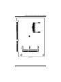
1
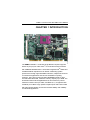
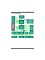
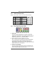
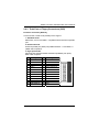
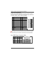
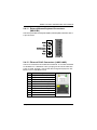
SHB211 Series ® ™ ® Intel Core 2 Duo/Celeron M CPU PICMG 1.3 Half-Size Single Board Computer User’s Manual Disclaimers This manual has been carefully checked and believed to contain accurate information. AXIOMTEK Co., Ltd. assumes no responsibility for any infringements of patents or any third party’s rights, and any liability arising from such use. AXIOMTEK does not warrant or assume any legal liability or responsibility for the accuracy, completeness or usefulness of any information in this document. AXIOMTEK does not make any commitment to update the information in this manual. AXIOMTEK reserves the right to change or revise this document and/or product at any time without notice. No part of this document may be reproduced, stored in a retrieval system, or transmitted, in any form or by any means, electronic, mechanical, photocopying, recording, or otherwise, without the prior written permission of AXIOMTEK Co., Ltd. CAUTION If you replace wrong batteries, it causes the danger of explosion. It is recommended by the manufacturer that you follow the manufacturer’s instructions to only replace the same or equivalent type of battery, and dispose of used ones. ©Copyright 2009 AXIOMTEK Co., Ltd. All Rights Reserved April 2009, Version A1 Printed in Taiwan ii ESD Precautions Computer boards have integrated circuits sensitive to static electricity. To prevent chipsets from electrostatic discharge damage, please take care of the following jobs with precautions: Do not remove boards or integrated circuits from their anti-static packaging until you are ready to install them. Before holding the board or integrated circuit, touch an unpainted portion of the system unit chassis for a few seconds. It discharges static electricity from your body. Wear a wrist-grounding strap, available from most electronic component stores, when handling boards and components. Trademarks Acknowledgments AXIOMTEK is a trademark of AXIOMTEK Co., Ltd. ® Windows is a trademark of Microsoft Corporation. ® AMI is a registered trademark of American Megatrends Inc. IBM, PC/AT, PS/2, VGA are trademarks of International Business Machines Corporation. ® TM ® Intel Core 2 Duo / Celeron M are trademarks of Intel Corporation. Winbond is a trademark of Winbond Electronics Corp. Other brand names and trademarks are the properties and registered brands of their respective owners. iii Table of Contents Disclaimers ........................................................................................................... ii ESD Precautions ................................................................................................. iii CHAPTER 1 INTRODUCTION ..................................................................................... 1 1.1 1.2 Specifications ................................................................................... 2 Utilities Supported ............................................................................ 4 1.3 1.4 Block Diagram .................................................................................. 5 I/O Bracket ....................................................................................... 6 CHAPTER 2 JUMPERS AND CONNECTORS............................................................ 7 2.1 Board Dimensions ............................................................................ 7 2.2 2.3 Board Layout .................................................................................... 8 Jumper Settings ............................................................................. 10 2.3.1 2.3.2 COM1 Mode Select Jumpers (JP1, JP2, JP3) ............................... 11 Audio Output Selection Jumper (JP4) ............................................ 11 2.3.3 2.3.4 COM1~2 Mode Selection Jumpers (JP6, JP5) .............................. 12 CompactFlash™ Device Setting Jumper (JP8~11)........................ 14 2.3.5 2.3.6 ComplactFlash™ Voltage Selection Jumper (JP12) ...................... 14 Auto-Power Button Selection Jumper (JP13)................................. 14 2.3.7 2.3.8 USB Voltage Selection Jumpers (JP14, JP15, JP17) .................... 15 LVDS Voltage Selection Jumper (JP18) ........................................ 15 2.3.9 2.3.10 CMOS Clear Jumper (JP19) .......................................................... 16 NB PCIex16 Signal Mode Jumper (JP20-21)................................ 16 2.4.1 Connectors ..................................................................................... 17 Audio Connector (CN1) .................................................................. 19 2.4.2 2.4.3 Front Panel Connector (CN2)......................................................... 19 Print Port or Floppy Connectors (CN3) .......................................... 21 2.4.4 2.4.5 EPIC Power Connector (CN4)........................................................ 22 CPU & System Fan Connectors (CN5, CN7, CN8)........................ 23 2.4.6 2.4.7 SMBUS Connector (CN6) .............................................................. 23 Display Port Connector (SHB211PGGA, CN9) ............................. 24 2.4.8 2.4.9 VGA Connector (SHB211VGGA, CN10)........................................ 25 JST Connector for LVDS Flat Panel (CN11) .................................. 25 2.4.10 2.4.11 LVDS Backlight Connector (CN12) ................................................ 26 External Mouse/Keyboard Connectors (MS1/KB1)........................ 27 2.4.12 2.4.13 Ethernet RJ-45 Connectors (LAN1/LAN2) ..................................... 27 Serial Port Interface (COM1, COM2) ............................................. 28 2.4.14 2.4.15 SATA Connectors (SATA1, SATA2) .............................................. 28 USB Connectors (USB1, USB2) .................................................... 29 2.4.16 2.4.17 USB Connectors (USB3/USB4) ..................................................... 29 USB Connectors (USB5/USB6) ..................................................... 30 2.4 TM 2.4.18 CompactFlash Socket (SCF1) .................................................... 30 CHAPTER 3 HAREDWARE INSTALLATION............................................................ 32 3.1 3.2 iv Installing the Processor .................................................................. 32 Installing the Memory ..................................................................... 35 CHAPTER 4 HARDWARE DESCRIPTION................................................................ 36 4.1 Microprocessors ............................................................................. 36 4.2 4.3 BIOS............................................................................................... 36 System Memory ............................................................................. 36 4.4 4.5 I/O Port Address Map..................................................................... 37 Interrupt Controller (IRQ) Map........................................................ 39 CHAPTER 5 AMI BIOS SETUP UTILITY................................................................... 40 5.1 Starting ........................................................................................... 40 5.2 5.3 Navigation Keys ............................................................................. 40 Main Menu...................................................................................... 41 5.4 5.5 Advanced Menu ............................................................................. 42 PCI PnP Menu................................................................................ 58 5.6 5.7 Boot Menu ...................................................................................... 60 Security Menu ................................................................................ 62 5.8 5.9 Chipset Menu ................................................................................. 64 Exit Menu ....................................................................................... 67 CHPATER 6 INSTALLATION OF DRIVERS ............................................................. 70 6.1 Installing Chipset Driver ................................................................. 70 6.2 6.3 Installing AUDIO Driver .................................................................. 74 Installing VGA Driver ...................................................................... 76 6.4 Installing LAN Driver....................................................................... 80 APPENDIX A WATCHDOG TIMER ........................................................................... 84 Watchdog Timer Setting .................................................................................... 84 Using the Watchdog Function .......................................................................... 84 APPENDIX B PICMG v1.3 INTERFACE DEFINITION ............................................ 86 APPENDIX C CONFIGURING SATA FOR RAID FUNCTION ................................... 91 v MEMO vi SHB211 Socket P Half-Size SBC User’s Manual CHAPTER 1 INTRODUCTION The SHB211 PICMG 1.3 half-size Single Board Computer supports ® ® Socket P (478-pin) for Intel Core™ 2 Duo/Celeron M processors ® with FSB 800/1066 MHz MT/s. The board integrates Intel GM45 and ICH9M/ICH9M-E chipsets that can deliver outstanding system performance through high-bandwidth interfaces, multiple I/O functions for interactive applications and various embedded computing solutions. There are two 204-pin DDR3 SODIMM sockets for dual channel DDR3 800/1066, maximum memory capacity up to 8GB. The board also features dual Gigabit Ethernet, two serial ATA ports at maximum transfer rate up to 3Gbs, and RAID 0,1,5,10 (optional with ® ICH9M-E). Six USB 2.0 high speed compliant ports and built-in Intel HD Audio Digital Header can achieve the best stability and reliability for industrial applications. Introduction 1 SHB211 Socket P Half-Size SBC User’s Manual 1.1 Specifications CPU z ® ® Intel Core™ 2 Duo/Celeron M Processors System Chipset z ® Intel GM45 and ICH9M (optional with ICH9M-E) CPU Socket z Socket P (478-pin) z Front-Side Bus z 800/1066 MHz BIOS AMI BIOS via SPI interface with socket z System Memory Two 204-pin DDR3 SO-DIMM sockets Maximum up to 8GB DDR3 memory Supports DDR3 800/1066 memory z L2 Cache: integrated in CPU z Onboard Multi-I/O Parallel Port: one 26-pin 2.0 pitch box-header for shared FDD/LPT Serial Port: one for RS-232/422/485 (COM1) and one port for RS-232 (COM2) Two Serial ATA-2 ports z USB Interface Six USB ports compliant with USB Spec. Rev. 2.0 (two on the rear I/O, and four ports via wafer connectors) z Expansion Interface PCIe x16 for discrete graphic card or PCIe x1 deivces PCIe x4 for one PCIe x4 or four PCIe x1 I/O Deivces LPC interface z SSD 2 CompactFlash™ Type-II Socket via jMicron JM20330 SATA-to-PATA controller Introduction SHB211 Socket P Half-Size SBC User’s Manual z VGA Controller ® Chipset -- Intel GM45 GMCH Gen5 integrated graphic engine; support Microsoft DirectX 10, Blu-ray 40Mb/s Memory Size up to 256MB frame buffer sharing system memory Maximum Resolution – ◆ CRT – 2048 x 1536 @ 75Hz with 32-bit color ◆ LVDS LCD – 4:3 up to UXGA 1600 x 1200 Digital DisplayPort – 2048 x 1536 Output Interface -◆ CRT connector for DAC output ◆ DisplayPort connector (co-location with CRT D-Sub 15pin connector as an option) ◆ ◆ LVDS LCD with single/dual channel 18/24-bit mode z Ethernet Dual Gigabit Ethernet; 2 x RTL8111B z Serial ATA z Support Serial ATA/Serial ATA II Two Serial ATA-II ports, 3Gb/s performance and RAID 0,1,5,10 (optional with ICH9M-E) Audio ® Intel HD Audio Digital Header z Hardware Monitoring Support CPU/System temperature, CPU/System voltage, and CPU/System Smart Fan features z Watchdog Timer z Reset Supported (1-255 level) Dimensions 185mm x 126mm Introduction 3 SHB211 Socket P Half-Size SBC User’s Manual NOTE All specifications and images are subject to change without notice. 1.2 Utilities Supported ® z Intel GM45 Utility and Drivers z VGA Drivers Ethernet Utility and Drivers RAID Utility z z 4 Introduction SHB211 Socket P Half-Size SBC User’s Manual 1.3 Block Diagram Introduction 5 SHB211 Socket P Half-Size SBC User’s Manual 1.4 6 I/O Bracket Introduction SHB211 Socket P Half-Size SBC User’s Manual CHAPTER 2 JUMPERS AND CONNECTORS 2.1 Board Dimensions Jumpers and Connectors 7 SHB211 Socket P Half-Size SBC User’s Manual 2.2 Board Layout Component Side 8 Jumpers and Connectors SHB211 Socket P Half-Size SBC User’s Manual Solder Side Jumpers and Connectors 9 SHB211 Socket P Half-Size SBC User’s Manual 2.3 Jumper Settings Proper jumper settings configure the SHB211 to meet your application purpose. Jumper Jumper Setting JP1 COM1 Mode Selection Default: RS-232 Short 1-2 JP2 COM1 Mode Selection Default: RS-232 Short 3-5, 4-6 JP3 COM1 Mode Selection Default: RS-232 Short 3-5, 4-6 JP4 Audio Speak Out/Line Out Selection Default: Line Out Short 1-3, 2-4 JP5 COM2 Mode Select COM2 Pin 1: DCD COM2 Pin 8: RI Short 7-9 Short 8-10 COM1 Mode Select COM1 Pin 1: DCD Short 7-9 JP6 JP8~11 JP12 JP13 JP14 JP15 JP16 JP17 JP18 JP19 10 Default Setting COM1 Pin 8: RI CF Device Default: ON Short 8-10 Short 1-2 Compact Flash Voltage Selection Default: 3.3V Auto-Power Button Selection Default: Manual Power Button Short 1-2 Short 1-2 USB1,2 Voltage Selection Default: 5V Short 1-2 USB3,4 Voltage Selection Short 2-3 Default: 5V_SBY Digital Displayport only or concurrent with PCIE (SHB211 PGGA ) Short 1-2 Default: Digital Displayport concurrent with PCIE USB5,6 Voltage Selection Default: 5V_SBY Short 2-3 LVDS Voltage Selection Default: 3.3V Normal Operation/Clear CMOS setting Default: Normal Operation Short 1-2 Short 1-2 Jumpers and Connectors SHB211 Socket P Half-Size SBC User’s Manual Jumper JP20~21 Default Setting Jumper Setting NB PCIEx16 Signal MODE Default: PCIEx16 Short 2-3 -- The End -- 2.3.1 COM1 Mode Select Jumpers (JP1, JP2, JP3) These jumpers select the COM1 port’s communication mode to operate RS-232 or RS-422/485. Description Function COM1 Jumper Setting RS-232 (Default) JP1 JP2 JP3 RS-422 JP1 JP2 JP3 RS-485 JP1 JP2 JP3 2.3.2 Audio Output Selection Jumper (JP4) This jumper makes the selection of Audio output. Description Audio Line Out/ Speaker Out Function Jumper Setting Line Out (Default) Speak Out Jumpers and Connectors 11 SHB211 Socket P Half-Size SBC User’s Manual 2.3.3 COM1~2 Mode Selection Jumpers (JP6, JP5) These jumpers select the COM1, COM2 ports’ DCD and RI mode. Description COM1 DCD & RI Voltage Selection (JP6) Function Jumper Setting Pin 1=12V Pin 1=5V *Pin 1=DCD (Default) Pin 8=12V Pin 8=5V *Pin 8=RI (Default) 12 Jumpers and Connectors SHB211 Socket P Half-Size SBC User’s Manual Description COM2 DCD & RI Voltage Selection (JP5) Function Jumper Setting Pin 1=12V Pin 1=5V *Pin 1=DCD (Default) Pin 8=12V Pin 8=5V *Pin 8=RI (Default) Jumpers and Connectors 13 SHB211 Socket P Half-Size SBC User’s Manual 2.3.4 CompactFlash™ Device Setting Jumper (JP8~11) Jumper CF Device Description Jumper Setting Enable (Default) Description Jumper Setting Disable 2.3.5 ComplactFlash™ Voltage Selection Jumper (JP12) This jumper is to select the voltage for CompactFlashTM interface. Description Function Jumper Setting TM 3.3V (Default) CompactFlash Voltage Selection 5V 2.3.6 Auto-Power Button Selection Jumper (JP13) Use this jumper to select either Auto or Manual power button. Description Function Jumper Setting Auto-Power Button Manual Power Buttom Selection (Default) Automatic Power Button 14 Jumpers and Connectors SHB211 Socket P Half-Size SBC User’s Manual 2.3.7 USB Voltage Selection Jumpers (JP14, JP15, JP17) This jumper is to select the voltage for USB interface. Description USB Voltage Selection Function Jumper Setting 5V 5V_SBY 2.3.8 LVDS Voltage Selection Jumper (JP18) This jumper is to select the voltage for LVDS interface. Description LVDS Voltage Selection Function Jumper Setting 3.3V (Default) 5V Jumpers and Connectors 15 SHB211 Socket P Half-Size SBC User’s Manual 2.3.9 CMOS Clear Jumper (JP19) You may need to use this jumper to clear the CMOS memory if incorrect settings in the Setup Utility. Description CMOS Clear Function Jumper Setting Normal (Default) Clear CMOS 2.3.10 NB PCIex16 Signal Mode Jumper (JP20-21) This jumper is to select singal output for PCIe x16 Slot or Digital Display Port. Description North Bridge PCIEx16 Signal Mode Function Jumper Setting Display Port PCIEx16 (Default) 16 Jumpers and Connectors SHB211 Socket P Half-Size SBC User’s Manual 2.4 Connectors Connectors connect this board with other parts of the system. Loose or improper connection might cause problems. Make sure all connectors are properly and firmly connected. Here is a summary table shows you all connectors on the board. Connectors Label Audio Connector CN1 Front Panel Connector CN2 FDD / PARALLEL Connector CN3 EPIC Power Connector CN4 CPU FAN Connector CN5 SMBus Connector CN6 SYSTEM FAN Connector SYSTEM FAN Connector CN7 CN8 Display Port Connector CN9 VGA Connector CN10 LVDS Connector CN11 LVDS Backlight Connector Keyboard Connector CN12 KB1 Mouse Connector MS1 Ethernet 1 Connector LAN1 Ethernet 2 Connector LAN2 Serial Port1 Connector COM1 Serial Port2 Connector SATA1 Connector COM2 SATA1 SATA2 Connector SATA2 USB1 Connector USB1 USB2 Connector USB2 USB3 / USB 4 Connector USB5 / USB 6 Connector USB3 USB4 CF Connector DDRIII RAM Connector DDRIII RAM Connector Thermal Sensor Connector Jumpers and Connectors SCF1 DIMM1 SDIMM1 JP22 , JP23 17 SHB211 Socket P Half-Size SBC User’s Manual 18 Jumpers and Connectors SHB211 Socket P Half-Size SBC User’s Manual 2.4.1 Audio Connector (CN1) CN1 is a 10pin-header connector commonly used for the audio. Pin 2.4.2 Signal Pin Signal 1 MIC-IN 2 GND 3 Line In L 4 GND 5 Line In R 6 GND 7 Audio Out L 8 GND 9 Audio Out R 10 GND Front Panel Connector (CN2) Power LED This 3-pin connector denoted as Pin 1 and Pin 5 connects the system power LED indicator to such a switch on the case. Pin 1 is assigned as +, and Pin 5 as -. The Power LED lights up when the system is powered ON. Pin 3 is defined as GND. External Speaker and Internal Buzzer Connector Pin 2, 4, 6 and 8 can be connected to the case-mounted speaker unit or internal buzzer. While connecting the CPU card to an internal buzzer, please short pins 2-4; while connecting to an external speaker, you need to set pins 2-4 to Open and connect the speaker cable to pin 8 (+) and pin 2 (-). ATX Power On/Off Button This 2-pin connector denoted as Pin 9 and 10 connects the front panel’s ATX power button to the CPU card, which allows users to control ATX power supply to be power on/off. Jumpers and Connectors 19 SHB211 Socket P Half-Size SBC User’s Manual System Reset Switch Pin 11 and 12 can be connected to the case-mounted reset switch that reboots your computer instead of turning OFF the power switch. It is a better way to reboot your system for a longer life of the system’s power supply. HDD Activity LED This connection is linked to hard drive activity LED on the control panel. LED flashes when HDD is being accessed. Pin 13 and 14 connect the hard disk drive to the front panel HDD LED, Pin 13 assigned as -, and Pin 14 as +. 20 Jumpers and Connectors SHB211 Socket P Half-Size SBC User’s Manual 2.4.3 Print Port or Floppy Connectors (CN3) Print Port Connector [Default] This board has a multi-mode parallel port to support: 1. Standard mode IBM PC/XT, PC/AT and PS/2™ compatible with bi-directional parallel port 2. Enhanced mode Enhance parallel port (EPP) compatible with EPP 1.7 and EPP 1.9 (IEEE 1284 compliant) 3. High speed mode Microsoft and Hewlett Packard extended capabilities port (ECP) IEEE 1284 compliant Pin 1 Signal Strobe# Pin 2 Signal Auto Form Feed# 3 Data 0 4 Error# 5 Data 1 6 Initialize# 7 Data 2 8 Printer Select In# 9 Data 3 11 Data 4 10 GND 12 GND 13 Data 5 14 GND 15 Data 6 16 GND 17 Data 7 18 GND 19 Acknowledge# 20 GND 21 Busy 23 Paper Empty# 22 GND 24 GND 25 Printer Select 26 NC Jumpers and Connectors 21 SHB211 Socket P Half-Size SBC User’s Manual Floppy Connector [Optional] You can plug one end of FDD cable in the FDD connector, and the other end of cable to the FDD drive. The supported type of FDD drives are 360KB, 720KB, 1.2MB, 1.44MB and 2.88MB. Pin Signal Pin Signal 1 DRIVE0 2 NC 3 INDEX 4 NC 5 MOTOR ON 6 NC 7 DSKCHG 8 NC 9 DIR 11 STEP 10 GND 12 GND 13 WDATA 14 GND 15 WGATE 16 GND 17 TRK0 18 GND 19 WPT 21 RDATA 20 GND 22 GND 23 HDSEL 24 GND 25 DSKCHG 26 NC The Parallel port and Floppy drive share the same connector so that you can select only one out of them. The parallel port is the default setting. 2.4.4 EPIC Power Connector (CN4) Pin 22 Signal Pin Signal 1 PSON# 6 5VSB 2 GND 7 +5V 3 GND 8 +5V 4 +12V 9 -12V 5 +3.3V 10 GND Jumpers and Connectors SHB211 Socket P Half-Size SBC User’s Manual 2.4.5 CPU & System Fan Connectors (CN5, CN7, CN8) CN5 is a fan connector for CPU, and CN7, CN8 for system. Pentium microprocessors require a fan for heat dispensing. The CPU/System fan connectors respectively provide power to the CPU/System fans. Pin Signal 1 GND 2 +12V 3 Sensor 2.4.6 SMBUS Connector (CN6) Connector CN5 is for SMBUS interface support. Pin Signal 1 CLOCK 2 DATA 3 GND Jumpers and Connectors 23 SHB211 Socket P Half-Size SBC User’s Manual 2.4.7 Display Port Connector (SHB211PGGA, CN9) Pin Signal 1 DPB_LANE0 2 GND 3 DPB_LANE0# 4 DPB_LANE1 5 6 GND DPB_LANE1# 7 DPB_LANE2 8 GND 9 DPB_LANE2# 10 11 DPB_LANE3 GND 12 DPB_LANE3# 13 GND 14 GND 15 16 DPB_AUX GND 17 DPB_AUX# 18 DPB_HPDE 19 N.C. 20 3.3V 24 1 20 Jumpers and Connectors SHB211 Socket P Half-Size SBC User’s Manual 2.4.8 VGA Connector (SHB211VGGA, CN10) CN10 is a standard 15-pin pin DB15 connector commonly used for the CRT VGA display. Pin Signal Pin Signal Pin Signal 1 Red 2 Green 3 Blue 4 N/A 5 AGND 6 CRT_DET# 7 AGND 10 AGND 8 AGND 11 N/A 9 VGA_5V 12 DDC DAT 13 Horizontal Sync 14 Vertical Sync 15 DDC CLK 2.4.9 JST Connector for LVDS Flat Panel (CN11) Pin 1 3 Signal VCCM VCCM Pin 2 4 Signal VCCM VCCM 5 VCCM 6 VCCM 7 N.C. 8 N.C. 9 GND 10 GND 11 13 Channel B D3Channel B D3+ 12 14 Channel B D0Channel B D0+ 15 GND 16 GND 17 Channel B CLK- 18 Channel B D1- 19 Channel B CLK+ 20 Channel B D1+ 21 GND 22 GND 23 25 Channel A D0Channel A D0+ 24 26 Channel B D2Channel B D2+ 27 GND 28 GND 29 Channel A D1- 30 Channel A D3- 31 Channel A D1+ 32 Channel A D3+ Jumpers and Connectors 25 SHB211 Socket P Half-Size SBC User’s Manual 33 Pin GND 34 Pin GND 35 37 Channel A D2Channel A D2+ 36 38 Channel A CLKChannel A CLK+ 39 GND 40 GND Signal Signal 2.4.10 LVDS Backlight Connector (CN12) The 7-pin inverter connector on the SHB211 is with Hirose connector. The matching connector is strongly recommended to use Hirose DF137S-1.25C. Pin 26 Signal 1 12V 2 12V 3 5V 4 ENABLE 5 6 GND GND 7 GND Jumpers and Connectors SHB211 Socket P Half-Size SBC User’s Manual 2.4.11 External Mouse/Keyboard Connectors (MS1/KB1) The board provides the Keyboard (KB1)/ Mouse (MS1) interface with a 5-pin connector. Clock 1 Data 2 No Connection 3 GND 4 Power 5 2.4.12 Ethernet RJ-45 Connectors (LAN1/LAN2) The RJ-45 connector LAN1/LAN2 is for Ethernet. To connect the board to 100-Base-T or 1000-Base-T hub, just plug one end of the cable into LAN1 or LAN2, and then, connect the other end (phone jack) to a 100Base-T hub or 1000-Base-T hub. Pin Signal 1 Tx+ (Data transmission positive) 2 Tx- (Data transmission negative) 3 Rx+(Data reception positive) 4 RJ-1(For 100 base T-Only) 5 RJ-1(For 100 base T-Only) 6 Rx- (Data reception negative) 7 RJ-1(For 100 base T-Only) 8 RJ-1(For 100 base T-Only) A Active LED B 100/1000 LAN LED Jumpers and Connectors 27 SHB211 Socket P Half-Size SBC User’s Manual 2.4.13 Serial Port Interface (COM1, COM2) The serial interface for the board consists of COM1 port support RS232/422/485(COM1) and COM2 (COM2) supports RS-232. Pin Signal Pin Signal 1 Data Carrier Detect (DCD) 2 Data Set Ready (DSR) 3 Receive Data (RXD) 4 Request to Send (RTS) 5 Transmit Data (TXD) 6 Clear to Send (CTS) 7 Data Terminal Ready (DTR) 8 Ring Indicator (RI) 9 Ground (GND) 10 NC 2.4.14 SATA Connectors (SATA1, SATA2) These SATA connectors SATA1 and SATA2 are for high-speed SATA interface ports and they can be connected to hard disk devices. Pin Signal Pin 1 GND 2 SATA_TX+ 3 SATA_TX- 4 GND 5 SATA_RX- 6 SATA_RX+ 7 GND 7 28 Signal 1 Jumpers and Connectors SHB211 Socket P Half-Size SBC User’s Manual 2.4.15 USB Connectors (USB1, USB2) The SHB211 Series features Universal Serial Bus (USB) connectors, compliant with USB 2.0 (480Mbps) that can be adapted to any USB peripherals, such as monitor, keyboard and mouse. Pin USB1 Signal 1 USB POWER 2 USB D1- 3 USB D1+ 4 GND Pin USB2 Signal 1 USB POWER 2 USB D2- 3 USB D2+ 4 GND 2.4.16 USB Connectors (USB3/USB4) The Universal Serial Bus (USB) connector on the board is for the installation of peripherals supporting the USB interface. USB3 and USB4 are 10-pin standard onboard USB connectors. Pin Signal Pin Signal 1 USB POWER 2 USB POWER 3 USB D3- 4 USB D4- 5 USB D3+ 6 USB D4+ 7 GND 8 GND 9 GND 10 GND USB3/USB4 Jumpers and Connectors 29 SHB211 Socket P Half-Size SBC User’s Manual 2.4.17 USB Connectors (USB5/USB6) The Universal Serial Bus (USB) connector on the board is for the installation of peripherals supporting the USB interface. USB5 and USB6 are 10-pin standard onboard USB connectors. Pin Signal Pin Signal USB5/USB6 1 USB POWER 2 USB POWER 3 USB D5- 4 USB D6- 5 USB D5+ 6 USB D6+ 7 GND 8 9 GND 10 GND GND 2.4.18 CompactFlashTM Socket (SCF1) TM The board is equipped with a CompactFlash disk socket on the TM solder side to support an IDE2 interface CompactFlash disk card. The socket is especially designed to avoid incorrect installation of the TM CompactFlash disk card. When installing or removing the TM CompactFlash disk card, please make sure the system power is off. TM The CompactFlash disk card is defaulted as the C: or D: disk drive in your PC system. Pin 30 Signal Pin Signal 1 GND 26 CD1- 2 3 Data 3 Data 4 27 28 Data 11 Data 12 4 Data 5 29 Data 13 5 Data 6 30 Data 14 6 Data 7 31 Data 15 7 8 CS0# Address 10 32 33 CS1# VS1# 9 ATASEL 34 IORD# 10 Address 9 35 IOWR# 11 Address 8 36 WE# 12 Address 7 37 INTR 13 Pin VCC 38 Pin VCC Signal Signal Jumpers and Connectors SHB211 Socket P Half-Size SBC User’s Manual 14 Address 6 39 15 Address 5 40 VS2# 16 17 Address 4 Address 3 41 42 RESET# IORDY# 18 Address 2 43 DMAREQ 19 Address 1 44 DMAACK- 20 Address 0 45 DASP# 21 22 Data 0 Data 1 46 47 PDIAG# Data 8 23 Data 2 48 Data 9 24 IOCS16# 49 Data 10 25 CD2# 50 GND Jumpers and Connectors CSEL# 31 SHB211 Socket P Half-Size SBC User’s Manual CHAPTER 3 HAREDWARE INSTALLATION ® Before installing the processor, please access Intel website for more detailed information http://www.intel.com . 3.1 Installing the Processor ® ® The Intel Core™ 2 Duo Mobile Processor or Mobile Intel ® Celeron Processors are available as a boxed processor for laptop computers in the micro-FCPGA form factor. Intel recommends the processor should be installed by a computer professional since this electronic device may cause serious damage to the installer, system and processor if installed improperly. Important: Before attempting to install a new processor, carefully review the documentation that came with your system and make sure that you will not be voiding your warranty by opening the computer or replacing your processor. Instructions ® 1. Make sure that your system can accommodate the Intel ® ® Core™ 2 Duo Mobile Processor or Mobile Intel Celeron Processors that you want to install. Check for motherboard, BIOS, and thermal compatibility by using the manufacturer's documentation for the laptop computer, or by contacting the vendor if necessary. This processor should only be installed in ® systems supporting the Intel Core™ 2 Duo Mobile ® ® Processor or Mobile Intel Celeron Processors. ® Important Notes: Do not use an Intel mobile processor in a desktop system and do not use a desktop processor in a mobile processor notebook. Since these processors have different electrical specifications, damage to the processor and system can occur. 2. Obtain access to your processor socket as described in the documentation for your system. 32 Hardware Installation SHB211 Socket P Half-Size SBC User’s Manual 3. If the cooling solution prevents you from accessing the processor socket, you may need to remove it. Instructions on how to remove your cooling solution should be provided in the documentation that came with the system. 4. To un-install the current processor, use a screwdriver to disengage (open) the socket actuator, as shown in Figure 1 below. (The most commonly used sockets are Molex* or FoxConn* sockets, so they are used in the illustrations below.) The socket actuator should open after only a half turn or so, and you should then be able to remove the processor with your fingers. Hardware Installation 33 SHB211 Socket P Half-Size SBC User’s Manual 34 Hardware Installation SHB211 Socket P Half-Size SBC User’s Manual 3.2 Installing the Memory The board supports two 204-pin DDR3 SO-DIMM memory sockets with maximum memory capacity up to 8GB. Please follow steps below to install the memory modules: 1 2 3 4 Push down latches on each side of the SO-DIMM socket. Align the memory module with the socket that notches of memory module must match the socket keys for a correct intallation. Install the memory module into the socket and push it firmly down until it is fully seated. The socket latches are levered upwards and clipped on to the edges of the SO-DIMM. Install any remaining SO-DIMM modules. Hardware Installation 35 SHB211 Socket P Half-Size SBC User’s Manual CHAPTER 4 HARDWARE DESCRIPTION 4.1 Microprocessors ® ® The SHB211 Series supports Intel Core™ 2 Duo/Celeron M ® processors, which make your system operated under Windows XP and Linux environments. The system performance depends on the microprocessor. Make sure all correct settings are arranged for your installed microprocessor to prevent the CPU from damages. 4.2 BIOS The SHB211 Series uses AMI Plug and Play BIOS with a single 8Mbit SPI Flash. 4.3 System Memory The SHB211 Series supports two 204-pin DDR3 DIMM sockets for a maximum memory of 8GB DDR3 SDRAMs. The memory module can come in sizes of 64MB, 128MB, 256MB, 512MB, 1GB and 2GB. 36 Hardware Description SHB211 Socket P Half-Size SBC User’s Manual 4.4 I/O Port Address Map ® ® The Intel Core™ 2 Duo/Celeron M CPUs can communicate via I/O ports. There are total 1KB port addresses available for assignment to other devices via I/O expansion cards. Hardware Description 37 SHB211 Socket P Half-Size SBC User’s Manual 38 Hardware Description SHB211 Socket P Half-Size SBC User’s Manual 4.5 Interrupt Controller (IRQ) Map The SHB211 Series is a 100% PC compatible control board. It consists of 16 interrupt request lines, and four out of them can be programmable. The mapping list of the 16 interrupt request lines is shown as the following table. Hardware Description 39 SHB211 Socket P Half-Size SBC User’s Manual CHAPTER 5 AMI BIOS SETUP UTILITY This chapter provides users with detailed description how to set up basic system configuration through the AMIBIOS8 BIOS setup utility. 5.1 Starting To enter the setup screens, follow the steps below: 1. 2. Turn on the computer and press the <Del> key immediately. After you press the <Delete> key, the main BIOS setup menu displays. You can access the other setup screens from the main BIOS setup menu, such as the Chipset and Power menus. 5.2 Navigation Keys The BIOS setup/utility uses a key-based navigation system called hot keys. Most of the BIOS setup utility hot keys can be used at any time during the setup navigation process. These keys include <F1>, <F10>, <Enter>, <ESC>, <Arrow> keys, and so on. Note Some of navigation keys differ from one screen to another. ÆÅ Left/Right ÇÈ Up/Down +− Plus/Minus 40 The Left and Right <Arrow> keys allow you to select a setup screen. The Up and Down <Arrow> keys allow you to select a setup screen or sub-screen. The Plus and Minus <Arrow> keys allow you to change the field value of a particular setup item. Tab The <Tab> key allows you to select setup fields. F1 The <F1> key allows you to display the General Help screen. F10 The <F10> key allows you to save any changes you have made and exit Setup. Press the <F10> key to save your changes. AMI BIOS Setup Utility SHB211 Socket P Half-Size SBC User’s Manual Esc Enter 5.3 The <Esc> key allows you to discard any changes you have made and exit the Setup. Press the <Esc> key to exit the setup without saving your changes. The <Enter> key allows you to display or change the setup option listed for a particular setup item. The <Enter> key can also allow you to display the setup sub- screens. Main Menu When you first enter the Setup Utility, you will enter the Main setup screen. You can always return to the Main setup screen by selecting the Main tab. There are two Main Setup options. They are described in this section. The Main BIOS Setup screen is shown below. z System Time/Date Use this option to change the system time and date. Highlight System Time or System Date using the <Arrow> keys. Enter new values through the keyboard. Press the <Tab> key or the <Arrow> keys to move between fields. The date must be entered in MM/DD/YY format. The time is entered in HH:MM:SS format. AMI BIOS Setup Utility 41 SHB211 Socket P Half-Size SBC User’s Manual 5.4 Advanced Menu The Advanced menu allows users to set configuration of the CPU and other system devices. You can select any of the items in the left frame of the screen to go to the sub menus: y y y y y y y y y y y y CPU Configuration IDE Configuration Floppy Configuration SuperIO Configuration Hardware Health Configuration ACPI Configuration AHCI Configuration APM Configuration Event Log Configuration Intel VT-d Configuration Smbios Configuration USB Configuration For items marked with “f”, please press <Enter> for more options. 42 AMI BIOS Setup Utility SHB211 Socket P Half-Size SBC User’s Manual z CPU Configuration This screen shows the CPU Configuration, and you can change the value of the selected option. ¾ MPS Revision Use this item to select MPS (Multi Processor Specification) Revision 1.1 or 1.4. The default setting is 1.4. ¾ Hardware Prefetcher This item automatically analyzes its requirements and prefetches data and instructions from the memory. When enabled, the processor’s hardware prefetcher will be allowed to automatically prefetch data and code for the processor. ¾ Adjacent Cache Line Prefetch This item has a hardware adjacent cache line prefetch mechanism that automatically fetches extra cache line whenever the processor requests for a cache line. This reduces cache latency by making the next cache line immediately available if the processor requires it as well. The processor will retrieve the currently requested cache AMI BIOS Setup Utility 43 SHB211 Socket P Half-Size SBC User’s Manual line and the subsequent cache line when enabled. The processor will only retrieve the currently requested cache line when disabled. 44 ¾ Max CPUID Value Limit You can enable this item to let legacy operating systems boot even without support for CPUs with extended CPU ID functions. ¾ Intel (R) Virtualization Tech Use this feature to enable or disable the Intel Virtualization Technology (IVT) extensions, which allow multiple operating systems to run simultaneously on the same system. When the IVT extensions are enabled, it allows for hardware-assisted virtual machine management. ¾ Execute-Disable Bit Capability This item helps you enable or disable the No-Execution Page Protection Technology. ¾ Core Multi-Processing This feature controls the functionality of the Core MultiProcessing to allow the processor to execute multitasking function. ¾ Intel (R) SpeedStep (tm) tech This item helps you enable or disable the Intel SpeedStep Technology. ¾ Intel (R) C-STATE tech Use this item to enable or disable the C-State technology. AMI BIOS Setup Utility SHB211 Socket P Half-Size SBC User’s Manual z IDE Configuration You can use this screen to select options for the IDE Configuration, and change the value of the selected option. A description of the selected item appears on the right side of the screen. For items marked with “f”, please press <Enter> for more options. ¾ SATA#1 Configuration Use this item to control the onboard SATA controller. Here are the options for your selection, Compatible, Disabled, and Enhanced. ¾ Configure SATA#1 as Use this item to choose the SATA operation mode. Here are the options for your selection, IDE and AHCI. ¾ SATA#2 Configuration Use this item to control the onboard SATA controller. Here are the options for your selection, Enhanced and Disabled. ¾ Primary/Secondary/Third/Fourth IDE Master/Slave Select one of the hard disk drives to configure IDE devices installed in the system by pressing <Enter> for more AMI BIOS Setup Utility 45 SHB211 Socket P Half-Size SBC User’s Manual options. 46 AMI BIOS Setup Utility SHB211 Socket P Half-Size SBC User’s Manual z Floppy Configuration You can use this screen to select options for the Floppy Configuration, and change the value of the selected option. A description of the selected item appears on the right side of the screen. For items marked with “f”, please press <Enter> for more options. ¾ Floppy A This item selects the type of floppy disk installed in the computer. AMI BIOS Setup Utility 47 SHB211 Socket P Half-Size SBC User’s Manual z SuperIO Configuration You can use this screen to select options for the SuperIO Configuration, and change the value of the selected option. A description of the selected item appears on the right side of the screen. 48 ¾ OnBoard Floppy Controller Use this item to enable or disable the onboard floppy drive controller. ¾ Serial Port1 Address This option specifies the base I/O port address and Interrupt Request address of serial port 1. The Optimal setting is 3F8/IRQ4. The Fail-Safe default setting is Disabled. ¾ Serial Port2 Address This option specifies the base I/O port address and Interrupt Request address of serial port 2. The Optimal setting is 2F8/IRQ3. The Fail-Safe setting is Disabled. ¾ Serial Port2 Mode This item specifies the mode used by the serial port 2. AMI BIOS Setup Utility SHB211 Socket P Half-Size SBC User’s Manual ¾ z Parallel Port Address z Parallel Port Mode Select an operating mode for the onboard parallel (printer) port. z Parallel Port IRQ Use this item to set up the IRQ for onboard parallel port. Hardware Health Configuration This screen shows the Hardware Health Configuration, and a description of the selected item appears on the right side of the screen. ¾ H/W Health Function You can select this item Enabled for the Hardware Health Monitoring Device. The Hardware Health Event Monitoring displays the temperature of CPU and System, Fan Speed, Vcore, etc. ¾ SYSFAN/CPUFAN/AUXFAN Mode Setting These items can enable or disable the Smart Fan to adjust the CPU/system fan speed automatically in accordance with the current CPU temperature that can prevent the AMI BIOS Setup Utility 49 SHB211 Socket P Half-Size SBC User’s Manual system overheating. There are these options Manual Mode and Thermal Cruise Mode. z ACPI Configuration You can use this screen to select options for the ACPI Configuration, and change the value of the selected option. A description of the selected item appears on the right side of the screen. 50 ¾ General ACPI Configuration Scroll to this item and press <Enter> to view the General ACPI Configuration sub menu, which contains General ACPI (Advanced Configuration and Power Management Interface) options for your configuration. ¾ Advanced ACPI Configuration Scroll to this item and press <Enter> to view the Advanced ACPI Configuration sub menu, which contains Advanced ACPI (Advanced Configuration and Power Management Interface) options for your configuration. ¾ Chipset ACPI Configuration AMI BIOS Setup Utility SHB211 Socket P Half-Size SBC User’s Manual Scroll to this item and press <Enter> to view the Chipset ACPI Configuration sub menu, which contains Chipset ACPI (Advanced Configuration and Power Management Interface) options for your configuration. z AHCI Configuration You can use this screen to select options for the AHCI Configuration, and change the value of the selected option. A description of the selected item appears on the right side of the screen. ¾ AHCI BIOS Support You can enable or disable this item to control the AHCI function of the SATA controller. AMI BIOS Setup Utility 51 SHB211 Socket P Half-Size SBC User’s Manual z APM Configuration You can use this screen to select options for the APM Configuration, and change the value of the selected option. A description of the selected item appears on the right side of the screen. ¾ 52 Power Management Set this value to allow Power Management/APM support. The default setting is Enabled. Disabled Set this value to prevent the chipset power management and APM (Advanced Power Management) features. Enabled Set this value to allow the chipset power management and APM (Advanced Power Management) features. This is the default setting. AMI BIOS Setup Utility SHB211 Socket P Half-Size SBC User’s Manual ¾ Power Button Mode This option specifies how the externally mounted power button on the front of the computer chassis is used. The default setting is On/Off. On/Off Pushing the power button turns the computer on or off. This is the default setting. This is the default setting. Standby Pushing the power button places the computer in Standby mode. Suspend Pushing the power button places the computer in Suspend mode or Full On power mode. ¾ Video Power Down Mode This option specifies the Power State that the video subsystem enters when the BIOS places it in a power saving state after the specified period of display inactivity has expired. The default setting is Suspend. Disabled This setting prevents the BIOS from initiating any power saving modes concerned with the video display or monitor. Standby This option places the monitor into standby mode after the specified period of display inactivity has expired. This means the monitor is not off. The screen will appear blacked out. The standards do not cite specific power ratings because they vary from monitor to monitor. Suspend This option places the monitor into suspend mode after the specified period of display inactivity has expired. This means the monitor is not off. The screen will appear blacked out. The standards do not cite specific power ratings because they vary from monitor to monitor, but this setting use less power than Standby mode. This is the default setting. ¾ Hard Disk Drive Power Down Mode This option specifies the power conserving state that the hard disk drive enters after the specified period of hard drive inactivity has expired. The default setting is Suspend. Disabled This setting prevents hard disk drive power down mode. AMI BIOS Setup Utility 53 SHB211 Socket P Half-Size SBC User’s Manual 54 Standby This option stops the hard disk drives from spinning during a system standby. Suspend This option cuts the power to the hard disk drives during a system suspend. This is the default setting. ¾ Throttle Slow Clock Ratio Use this item to specify the speed of the system clock when running the power saving states. ¾ System Thermal Use this item to enable or disable the function of system temperature control. ¾ Resume On Ring This item enables or disables the function of Resume On Ring that resume the system through incoming calls. ¾ Resume On RTC Alarm You can set “Resume On RTC Alarm” item to enabled and key in Data/time to power on system. AMI BIOS Setup Utility SHB211 Socket P Half-Size SBC User’s Manual z Event Log Configuration This screen shows the Event Log Configuration, and a description of the selected item appears on the right side of the screen. ¾ View Event Log This item is to display the system events in the System Event Log. ¾ Mark all events as read This item is to mark all events in the log as read. ¾ Clear Event Log Enable this item is to clear the event log each time the system is rebooted. AMI BIOS Setup Utility 55 SHB211 Socket P Half-Size SBC User’s Manual z Smbios Configuration You can use this screen to select options for the Smbios Configuration, and change the value of the selected option. A description of the selected item appears on the right side of the screen. ¾ 56 Smbios Smi Support When this item is enabled, the system can support the SMBIOS SMI wrapper for the PnP. AMI BIOS Setup Utility SHB211 Socket P Half-Size SBC User’s Manual z USB Configuration You can use this screen to select options for the USB Configuration, and change the value of the selected option. A description of the selected item appears on the right side of the screen. ¾ USB Functions This item allows you to enable or disable USB functions. ¾ Legacu USB Support Use this item to enable or disable support for USB device on legacy operating system. The default setting is Enabled. AMI BIOS Setup Utility 57 SHB211 Socket P Half-Size SBC User’s Manual 5.5 PCI PnP Menu The PCI PnP menu allows users to change the advanced settings for PCI/PnP devices. 58 ¾ Clear NVRAM Use this item to clear the data in the NVRAM (CMOS). Here are the options for your selection, No and Yes. ¾ Plug & Play O/S When the setting is No, Use this item to configure all the devices in the system. When the setting is Yes and if you install a Plug and Play operating system, the operating system configures the Plug and Play devices not required for boot. The default setting is No. ¾ PCI Latency Timer This item controls how long a PCI device can hold the PCI AMI BIOS Setup Utility SHB211 Socket P Half-Size SBC User’s Manual bus before another takes over. The longer the latency, the longer the PCI device can retain control of the bus before handing it over to another PCI device. There are several options for your selection. ¾ Allocate IRQ to PCI VGA This item allows BIOS to choose an IRQ to assign for the PCI VGA card. Here are the options for your selection, No and Yes. ¾ Palette Snooping Some old graphic controllers need to “snoop” on the VGA palette, and then map it to their display as a way to provide boot information and VGA compatibility. This item allows such snooping to take place. Here are the options for your selection, Disabled and Enabled. ¾ PCI IDE BusMaster This item is a toggle for the built-in driver that allows the onboard IDE controller to perform DMA (Direct Memory Access) transfer. Here are the options for your selection, Disabled and Enabled. ¾ OffBoard PCI/ISA IDE Card This item is for any other non-onboard PCI/ISA IDE controller adapter. There are several options for your selection. ¾ IRQ3/4/5/7/9/10/11/14/15 These items will allow you to assign each system interrupt a type, depending on the type of device using the interrupt. The option “Available” means the IRQ is going to assign automatically. Here are the options for your selection, Available and Reserved. ¾ DMA Channel 0/1/3/5/6/7 These items will allow you to assign each DMA channel a type, depending on the type of device using the channel. The option “Available” means the channel is going to assign automatically. Here are the options for your selection, Available and Reserved. AMI BIOS Setup Utility 59 SHB211 Socket P Half-Size SBC User’s Manual 5.6 Boot Menu The Boot menu allows users to change boot options of the system. You can select any of the items in the left frame of the screen to go to the sub menus: y Boot Settings Configuration For items marked with “f”, please press <Enter> for more options. 60 AMI BIOS Setup Utility SHB211 Socket P Half-Size SBC User’s Manual z Boot Settings Configuration ¾ Quick Boot Enabling this item lets the BIOS skip some power on self tests (POST). The default setting is Enabled. ¾ LAN1/LAN2 Boot Use these items to enable or disable the Boot ROM function of the onboard LAN chip when the system boots up. ¾ AddOn ROM Display Mode This item selects the display mode for option ROM. The default setting is Force BIOS. ¾ Boot Num-Lock Use this item to select the power-on state for the NumLock. The default setting is On. ¾ Wait For ‘F1’ Of Error If this item is enabled, the system waits for the F1 key to be pressed when error occurs. The default setting is Enabled. ¾ Hit ‘DEL’ Message Display If this item is enabled, the system displays the message “Press DEL to run Setup” during POST.The default setting AMI BIOS Setup Utility 61 SHB211 Socket P Half-Size SBC User’s Manual is Enabled. ¾ 5.7 Interrupt 19 Capture If this item is enabled, this function makes the option ROMs to trap Interrupt 19. The default setting is Disabled. Security Menu The Security menu allows users to change the security settings for the system. 62 ¾ Supervisor Password This item indicates whether a supervisor password has been set. If the password has been installed, Installed displays. If not, Not Installed displays. ¾ User Password This item indicates whether a user password has been set. If the password has been installed, Installed displays. If not, Not Installed displays. ¾ Change Supervisor Password Select this option and press <Enter> to access the sub menu. You can use the sub menu to change the supervisor AMI BIOS Setup Utility SHB211 Socket P Half-Size SBC User’s Manual password. ¾ Change User Password Select this option and press <Enter> to access the sub menu. You can use the sub menu to change the user password. ¾ Boot Sector Virus Protection This option is near the bottom of the Security Setup screen. The default setting is Disabled Disabled Enabled Set this value to prevent the Boot Sector Virus Protection. This is the default setting. Select Enabled to enable boot sector protection. It displays a warning when any program (or virus) issues a Disk Format command or attempts to write to the boot sector of the hard disk drive. If enabled, the following appears when a write is attempted to the boot sector. You may have to type N several times to prevent the boot sector write. Boot Sector Write! Possible VIRUS: Continue (Y/N)? _ The following appears after any attempt to format any cylinder, head, or sector of any hard disk drive via the BIOS INT 13 Hard disk drive Service: Format!!! Possible VIRUS: Continue (Y/N)? AMI BIOS Setup Utility 63 SHB211 Socket P Half-Size SBC User’s Manual 5.8 Chipset Menu The Chipset menu allows users to change the advanced chipset settings. You can select any of the items in the left frame of the screen to go to the sub menus: y y North Bridge Configuration South Bridge Configuration For items marked with “f”, please press <Enter> for more options. 64 AMI BIOS Setup Utility SHB211 Socket P Half-Size SBC User’s Manual z North Bridge Configuration ¾ Memory Hole You can reserve this area of system memory for ISA adapter ROM. When this area is reserved it cannot be cached. Check the user information of peripherals that need to use this area o f system memory for the memory requirements. Here are the options, Disabled and 15M-16M. ¾ Boot Graphic Adapter Priority This item allows you to select the graphics controller as the primary boot device. ¾ Internal Graphics Mode Select This item allows you to select the amout of system memory used by the internal graphics device. ¾ PEG Port Configuration/PEG Port This item is a toggle to enable or disable the PCI Express port. Here are the options for your selection, Auto and Disabled. AMI BIOS Setup Utility 65 SHB211 Socket P Half-Size SBC User’s Manual ¾ z Video Function Configuration You can press <Enter> for the sub-menu to set up video function. South Bridge Configuration 66 ¾ USB Controller This item allows you to enable or disable USB function/controller. ¾ Restore on AC Power Loss This item can control how the PC will behave once power is restored following a power outage, or other unexpected shutdown. AMI BIOS Setup Utility SHB211 Socket P Half-Size SBC User’s Manual ¾ 5.9 PCIE Port Configuration This item allows you to set or disable the PCI Express Ports. Exit Menu The Exit menu allows users to load your system configuration with optimal or failsafe default values. ¾ Save Changes and Exit When you have completed the system configuration changes, select this option to leave Setup and reboot the computer so the new system configuration parameters can take effect. Select Save Changes and Exit from the Exit menu and press <Enter>. Select Ok to save changes and exit. ¾ Discard Changes and Exit Select this option to quit Setup without making any permanent changes to the system configuration. Select Discard Changes and Exit from the Exit menu and press <Enter>. Select Ok to discard changes and exit. Discard Changes Use this item to abandon all changes. ¾ AMI BIOS Setup Utility 67 SHB211 Socket P Half-Size SBC User’s Manual 68 ¾ Load Optimal Defaults It automatically sets all Setup options to a complete set of default settings when you select this option. The Optimal settings are designed for maximum system performance, but may not work best for all computer applications. In particular, do not use the Optimal Setup options if your computer is experiencing system configuration problems. Select Load Optimal Defaults from the Exit menu and press <Enter>. ¾ Load Fail-Safe Defaults It automatically sets all Setup options to a complete set of default settings when you select this option. The Fail-Safe settings are designed for maximum system stability, but not maximum performance. Select the Fail-Safe Setup options if your computer is experiencing system configuration problems. Select Load Fail-Safe Defaults from the Exit menu and press <Enter>. Select Ok to load Fail-Safe defaults. AMI BIOS Setup Utility SHB211 Socket P Half-Size SBC User’s Manual MEMO AMI BIOS Setup Utility 69 SHB211 Socket P Half-Size SBC User’s Manual CHPATER 6 INSTALLATION OF DRIVERS The device drivers are located on the Product Information CD-ROM that comes with the SHB211 Series package. The auto-run function of drivers will guide you to install the utilities and device drivers under a Windows system. You can follow the onscreen instructions to install these devices: 6.1 Chipse VGA Audio LAN Installing Chipset Driver 1. Run the SETUP.EXE program from the driver directory in your driver CD. Click “Next” to next step. 2. 70 ® An Intel License Agreement appears to show you the important information. Click “Yes” to next step. Installation of Drivers SHB211 Socket P Half-Size SBC User’s Manual 3. Refer to the Readme file below to view the system requirements and installation information. 3-1 Please wait while running the following setup operations. Installation of Drivers 71 SHB211 Socket P Half-Size SBC User’s Manual 3-2 Please wait while running the following setup operations. 72 Installation of Drivers SHB211 Socket P Half-Size SBC User’s Manual 4. Click “Finish” to complete the setup process. 5. You will be asked to reboot your computer when the installation is completed. Please click “Yes, I want to restart my computer now” if you don’t need to install any other drivers. Otherwise, please click “No, I will restart my computer later”, and go on next step. Installation of Drivers 73 SHB211 Socket P Half-Size SBC User’s Manual 6.2 Installing AUDIO Driver 1. 74 Run the InstallShield Wizard for Realtek High Definition Audio Driver from the driver directory in your driver CD. Click “Next” to next step. Installation of Drivers SHB211 Socket P Half-Size SBC User’s Manual 2. Click “Install” to start the installation, and wait while running the installation operation. 3. Click “Finish” to complete the installation. Installation of Drivers 75 SHB211 Socket P Half-Size SBC User’s Manual 6.3 Installing VGA Driver 1. Run the SETUP.EXE program from the driver directory in your driver CD. Click “Next” to next step. (1-1) 76 Installation of Drivers SHB211 Socket P Half-Size SBC User’s Manual (1-2) (1-3) 2. ® An Intel License Agreement appears to show you the important information. Click “Yes” to next step. Installation of Drivers 77 SHB211 Socket P Half-Size SBC User’s Manual 78 3. The message of Readme File Information appears to show you the system requirements and installation information. Please click “Next”. 4. Please wait while running the following setup operations. When this message appears, please click “Next”. Installation of Drivers SHB211 Socket P Half-Size SBC User’s Manual 5. Click “Finish” to complete the setup process. 6. You will be asked to reboot your computer when the installation is completed. Please click “Yes, I want to restart my computer now” if you don’t need to install any other drivers. Otherwise, please click “No, I will restart my computer later”, and click “Finish” to complete the installation. Installation of Drivers 79 SHB211 Socket P Half-Size SBC User’s Manual 6.4 Installing LAN Driver 1. Run the InstallShield Wizard for Network connections from the driver directory in your driver CD. Click “Next” for next step. 80 Installation of Drivers SHB211 Socket P Half-Size SBC User’s Manual 2. 3. Click “Install” to start the installation. Please wait while running the following installation operation. Installation of Drivers 81 SHB211 Socket P Half-Size SBC User’s Manual 4. 82 Click “Finish” to complete the installation. Installation of Drivers SHB211 Socket P Half-Size SBC User’s Manual MEMO Installation of Drivers 83 SHB211 Socket P Half-Size SBC User’s Manual APPENDIX A WATCHDOG TIME R Watchdog Timer Setting After the system stops working for a while, it can be auto-reset by the Watchdog Timer. The integrated Watchdog Timer can be set up in the system reset mode by program. Using the Watchdog Function Start ↓ Un-Lock WDT :O 2E 87 ; Un-lock super I/O O 2E 87 ; Un-lock super I/O ↓ Set WDT Funtion O 2E 2D O 2F 20 Select Logic device O 2E 07 O 2F 08 ↓ Activate WDT :O 2E 30 O 2F 01 Set Second or Minute O 2E F5 O 2F N N=00 or 08(See below table) ↓ Set base timer :O 2E F6 O 2F M=00,01,02,…FF(Hex) ,Value=0 to 255 ↓ WDT counting re-set timer 84 :O 2E F6 O 2F M ; M=00,01,02,…FF(See below table) Watchdog Timer SHB211 Socket P Half-Size SBC User’s Manual ↓ IF No re-set timer IF to disable WDT :WDT time-out, generate RESET :O 2E 30 O 2F 00 ; Can be disable at any time N=00 M= 00h: Time-out Disable 01h: Time-out occurs after 1 second 02h: Time-out occurs after 2 second 03h: Time-out occurs after 3 second ………………………....................................... FFh: Time-out occurs after 255 second N=08 M= 00h: Time-out Disable 01h: Time-out occurs after 1 minute 02h: Time-out occurs after 2 minutes 03h: Time-out occurs after 3 minutes ………………………....................................... FFh: Time-out occurs after 255 minutes Watchdog Timer 85 SHB211 Socket P Half-Size SBC User’s Manual APPENDIX B PICMG v1.3 INTE RFACE DEFINITION x16 PCIe Connector A Side B x16 PCIe Connector C Side A Side B Side A 1 N.C N.C 1 USB0P GND 2 GND 3 N.C GND N.C 2 USB0N 3 GND GND USB1P 4 N.C N.C 4 GND USB1N 5 N.C WAKE# 5 USB2P GND 6 PWRBT# PME# 6 USB2N GND 7 PWRGD PSON# 7 GND USB3P 8 SHB_RST# 9 CFG0 PERST# CFG1 8 GND 9 USBOC0# USB3N GND 10 CFG2 CFG3 11 RSVD GND 10 GND 11 USBOC2# Mechanical Key USBOC1# GND 12 GND 13 b_PETp0 N.C GND 12 GND 13 N.C USBOC3# GND 14 b_PETn0 GND 14 N.C GND 15 GND b_PERp0 15 GND N.C 16 GND b_PERn0 16 GND N.C 17 b_PETp1 18 b_PETn1 GND GND 17 N.C 18 N.C GND GND 19 GND b_PERp1 19 GND N.C 20 GND b_PERn1 20 GND N.C 21 b_PETp2 GND 21 N.C GND 22 b_PETn2 GND 22 N.C GND 23 GND 24 GND b_PERp2 b_PERn2 23 GND 24 GND N.C N.C 25 b_PETp3 GND 25 N.C GND 26 b_PETn3 GND 26 N.C GND 27 GND b_PERp3 27 GND N.C 28 GND b_PERn3 28 GND Mechanical Key N.C 86 PICMG v1.3 Interface Definition SHB211 Socket P Half-Size SBC User’s Manual 29 REFCLK0+ 30 REFCLK0- GND GND 29 N.C 30 N.C GND GND 31 GND REFCLK1+ 31 N.C N.C 32 RSVD REFCLK1- 32 N.C N.C 33 REFCLK2+ GND 33 N.C N.C 34 REFCLK2- GND 34 N.C GND 35 GND 36 RSVD REFCLK3+ REFCLK3- 35 N.C 36 GND GND N.C 37 REFCLK4+ GND 37 GND N.C 38 REFCLK4- GND 38 N.C GND 39 GND N.C 39 N.C GND 40 RSVD 41 N.C N.C GND 40 GND 41 GND N.C N.C 42 N.C GND 42 +3.3V +3.3V 43 GND N.C 43 +3.3V +3.3V 44 GND N.C 44 +3.3V +3.3V 45 a_PETp0 46 a_PETn0 GND GND 45 +3.3V 46 +3.3V +3.3V +3.3V 47 GND a_PERp0 47 +3.3V +3.3V 48 GND a_PERn0 48 +3.3V +3.3V 49 a_PETp1 GND 49 +3.3V +3.3V 50 a_PETn1 GND 50 +3.3V +3.3V 51 GND 52 GND a_PERp1 a_PERn1 51 GND 52 GND GND GND 53 a_PETp2 GND 53 GND GND 54 a_PETn2 GND 54 GND GND 55 GND a_PERp2 55 GND GND 56 GND 57 a_PETp3 a_PERn2 GND 56 GND 57 GND GND GND 58 a_PETn3 GND 58 GND GND 59 GND a_PERp3 59 +5V +5V 60 GND a_PERn3 60 +5V +5V 61 a_PETp4 62 a_PETn4 GND GND 61 +5V 62 +5V +5V +5V 63 GND a_PERp4 63 GND GND PICMG v1.3 Interface Definition 87 SHB211 Socket P Half-Size SBC User’s Manual Mechanical Key 64 GND a_PERn4 64 GND GND 65 a_PETp5 66 a_PETn5 GND GND 65 GND 66 GND GND GND 67 GND a_PERp5 67 GND GND 68 GND a_PERn5 68 GND GND 69 a_PETp6 GND 69 GND GND 70 a_PETn6 71 GND GND a_PERp6 70 GND 71 GND GND GND 72 GND a_PERn6 72 GND GND 73 a_PETp7 GND 73 +12V +12V 74 a_PETn7 GND 74 +12V +12V 75 GND a_PERp7 75 +12V +12V 76 GND 77 N.C a_PERn7 GND 76 +12V 77 +12V +12V +12V 78 +3.3V +3.3V 78 +12V +12V 79 +3.3V +3.3V 79 +12V +12V 80 +3.3V +3.3V 80 +12V +12V 81 +3.3V +3.3V 81 +12V +12V 82 RSVD RSVD X8 PCIe Connector B Side B 82 +12V +12V X8 PCIe Connector D Side A Side B Side A 1 +5Vaux +5Vaux 1 INTB# INTA# 2 GND 3 a_PETp8 N.C GND 2 INTD# 3 GND INTC# N.C 4 a_PETn8 GND 4 REQ3# GNT3# 5 GND a_PERp8 5 REQ2# GNT2# 6 GND a_PERn8 6 PCI_RST# GNT1# 7 a_PETp9 GND 7 REQ1# GNT0# 8 a_PETn9 9 GND GND a_PERp9 8 REQ0# 9 N.C SERR# +3.3V 10 GND a_PERn9 11 N.C GND 12 GND 13 a_PETp10 88 N.C GND 10 GND 11 N.C Mechanical Key 12 CLKC 13 GND N.C GND CLKD +3.3V PICMG v1.3 Interface Definition SHB211 Socket P Half-Size SBC User’s Manual Mechanical Key 14 a_PETn10 GND 14 CLKA CLKB 15 GND a_PERp10 15 +3.3V GND 16 GND a_PERn10 16 AD31 GND 17 a_PETp11 GND 17 AD29 +3.3V 18 a_PETn11 GND 18 N.C AD30 19 GND 20 GND a_PERp11 a_PERn11 19 AD27 20 AD25 AD28 GND 21 a_PETp12 GND 21 GND AD26 22 a_PETn12 GND 22 C/BE3# AD24 23 GND a_PERp12 23 AD23 +3.3V 24 GND 25 a_PETp13 a_PERn12 GND 24 GND 25 AD21 AD22 AD20 26 a_PETn13 GND 26 AD19 N.C 27 GND a_PERp13 27 +5V AD18 28 GND a_PERn13 28 AD17 AD16 29 a_PETp14 30 a_PETn14 GND GND 29 C/BE2# 30 PCI_PRST# GND FRAME# 31 GND a_PERp14 31 IRDY# TRDY# 32 GND a_PERn14 32 DEVSEL# +5V 33 a_PETp15 GND 33 LOCK# STOP# 34 a_PETn15 GND 34 PERR# GND 35 GND 36 GND a_PERp15 a_PERn15 35 GND 36 PAR C/BE1# AD14 37 N.C GND 37 N.C GND 38 N.C N.C 38 GND AD12 39 GND GND 39 AD15 AD10 40 GND 41 GND GND GND 40 AD13 41 GND GND AD09 42 GND GND 42 AD11 C/BE0# 43 GND GND 43 AD08 GND 44 +12V +12V 44 GND AD06 45 +12V 46 +12V +12V +12V 45 AD07 46 AD04 AD05 GND 47 +12V +12V 47 GND AD02 48 +12V +12V 48 AD03 AD01 PICMG v1.3 Interface Definition 89 SHB211 Socket P Half-Size SBC User’s Manual Mechanical Key 49 +12V Note 90 +12V 49 AD00 GND Please contact your vendor to get the backplane design guide if it’s required. The backplane design guide is NDA required. PICMG v1.3 Interface Definition SHB211 Socket P Half-Size SBC User’s Manual APPENDIX C CONFIGURING SATA FOR RAID FUNCTION Configuring SATA Hard Drive(s) for RAID ® Function (Controller: Intel ICH9M-E only) Please follow up the steps below to configure SATA hard drive(s): (1) Install SATA hard drive(s) in your system. (2) Enter the BIOS Setup to configure SATA controller mode and boot sequence. (3) Configure RAID by the RAID BIOS. (4) Create a floppy disk for the SATA controller driver. (5) Install the SATA controller driver during the OS installation. Before you begin the SATA configuration, please prepare: (a) Two SATA hard drives (to ensure optimal performance, it is recommended that you use two hard drives with identical model and capacity). If you do not want to create RAID with the SATA controller, you may prepare only one hard drive. (b) An empty formatted floppy disk (c) Windows XP setup disk (1) Installing SATA hard drive(s) in your system Connect one end of the SATA signal cable to the rear of the SATA hard drive, and the other end to available SATA port(s) on the board. Then, connect the power connector of power supply to the hard drive. (2) Configuring SATA controller mode and boot sequence by the BIOS Setup You have to make sure whether the SATA controller is configured correctly by system BIOS Setup and set up BIOS boot sequence for the SATA hard drive(s). Configuring SATA for RAID Function 91 SHB211 Socket P Half-Size SBC User’s Manual (2)-1-1 92 Turn on your system, and then press the Del button to enter BIOS Setup during running POST (Power-On Self Test). If you want to create RAID, just go to the Advanced Settings menu/IDE configuration, select the Configure SATA#1 as, and press <Enter> for more options. Configuring SATA for RAID Function SHB211 Socket P Half-Size SBC User’s Manual (2)-1-2 A list of options appears, please select RAID. Configuring SATA for RAID Function 93 SHB211 Socket P Half-Size SBC User’s Manual (2)-2 (2)-3 94 Set CDROM for First Boot Device under the Boot Settings menu to boot CD-ROM after system restarts. Save and exit the BIOS Setup. Configuring SATA for RAID Function SHB211 Socket P Half-Size SBC User’s Manual (3) Configuring RAID by the RAID BIOS Enter the RAID BIOS setup utility to configure a RAID array. Skip this step and proceed to Section 4 if you do not want to create a RAID. (3)-1 After the POST memory testing and before the operating system booting, a message "Press <Ctrl-I> to enter Configuration Utility" shows up, accordingly, press <CTRL+ I> to enter the RAID BIOS setup utility. (3)-2 After you press <CTRL+ I>, the Create RAID Volume screen will appear. If you want to create a RAID array, select the Create RAID Volume option in the Main Menu and press ENTER. Configuring SATA for RAID Function 95 SHB211 Socket P Half-Size SBC User’s Manual (3)-3 After entering the CREATE VOLUME MENU screen, you can type the disk array name with 1~16 letters (letters cannot be special characters) in the item “Name”. When finished, press ENTER to select a RAID level. There are three RAID levels, RAID0, RAID1 and RAID5 & RAID10. Select a RAID level and press ENTER. 96 Configuring SATA for RAID Function SHB211 Socket P Half-Size SBC User’s Manual (3)-4 Set the stripe block size. The KB is the standard unit of stripe block size. The stripe block size can be 4KB to 128KB. After the setting, press ENTER for the array capacity. (3)-5 After setting all the items on the menu, select Create Volume and press ENTER to start creating the RAID array. Configuring SATA for RAID Function 97 SHB211 Socket P Half-Size SBC User’s Manual (3)-6 When prompting the confirmation, press “Y“ to create this volume, or “N“ to cancel the creation. After the creation is completed, you can see detailed information about the RAID Array in the DISK/VOLUME INFORMATION section, including RAID mode, disk block size, disk name, and disk capacity, etc. 98 Configuring SATA for RAID Function SHB211 Socket P Half-Size SBC User’s Manual Configuring SATA for RAID Function 99 SHB211 Socket P Half-Size SBC User’s Manual Delete RAID Volume If you want to delete a RAID volume, select the Delete RAID Volume option in Main Menu. Press ENTER and follow on-screen instructions. Please press [ESC] to exit the RAID BIOS utility. Now, you can proceed to install a SATA driver controller and the operating system. 100 Configuring SATA for RAID Function SHB211 Socket P Half-Size SBC User’s Manual (4) Making a SATA Driver Disk To install the operating system onto a serial ATA hard disk successfully, you need to install the SATA controller driver during the OS installation. Without the driver, the hard disk may not be recognized during the Windows setup process. First of all, please format a blank floppy disk. Secondly, follow up these steps below to produce a SATA driver disk. (4)-1 Users can insert the Driver CD and the formatted blank floppy disk in another system. And then, please execute the f6flpy32.exe file in the folder of the Driver CD. Note Please execute the f6flpy64.exe file, if installing 64-bit Windows Operating System. (4)-2 When this screen pops out, please click the “CONFIRM” button. Configuring SATA for RAID Function 101 SHB211 Socket P Half-Size SBC User’s Manual (4)-3 When the RAID Driver is written to the floppy disk, the SATA driver disk is completed. Note1 Please execute all of file of the f6flpy64 folder, if installing 64bit Windows Operating System. 102 Configuring SATA for RAID Function SHB211 Socket P Half-Size SBC User’s Manual (5) Installing the SATA controller driver during the OS installation Now, the SATA driver disk is ready, and BIOS settings configured, you can proceed to install Windows 2000/XP onto your SATA hard drive using the SATA driver. Here is an example for Windows XP installation. (5)-1 Restart your system to boot the Windows 2000/XP Setup disk, and press F6 button as soon as you see the message "Press F6 if you need to install a 3rd party SCSI or RAID driver". After pressing the F6 button, there will be a few moments for some files being loaded before next screen appears. Configuring SATA for RAID Function 103 SHB211 Socket P Half-Size SBC User’s Manual (5)-2 When you see the screen below, insert the floppy disk containing the SATA driver and press “S”. (5)-3 If the Setup correctly recognizes the driver of the floppy disk, a controller menu will appear below. Use the ARROW keys to select Intel(R) ICH8M-E/ICH9M-E SATA RAID Controller and press ENTER. Then it will begin to load the SATA driver from the floppy disk. Note 104 If a message on the screen saying that one or some file(s) cannot be found, please check the floppy disk or copy the Configuring SATA for RAID Function SHB211 Socket P Half-Size SBC User’s Manual correct SATA driver again from the driver CD. Configuring SATA for RAID Function 105 SHB211 Socket P Half-Size SBC User’s Manual MEMO 106 Configuring SATA for RAID Function