1
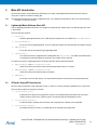
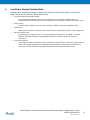
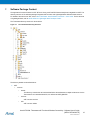
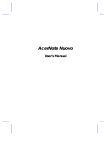
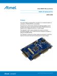
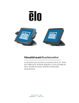
APPLICATION NOTE
Atmel AT03198: Thermostat with Touch and Wireless
Connectivity - Software User’s Guide
Atmel 32-bit Microcontroller
Introduction
This application note mainly describes the firmware architecture and the application
programming interfaces (API) of Thermostat with Touch and Wireless Connectivity
reference design (hereafter the Thermostat).
Features
•
•
•
•
•
•
Atmel® ATSAM4LC4C Microcontroller
Atmel AT86RF233 2.4GHz radio transceiver
Atmel Lightweight Mesh proprietary software stack
Atmel QTouch® Capacitive Touch Support
Atmel picoPower® Technology
Tickless FreeRTOS™
Figure 1.
Thermostat with Touch and Wireless Connectivity
Chapter 8 Getting Started Guide gives details about the setup and operation of the
Thermostat firmware.
The Thermostat is based on Atmel ATSAM4LC4C microcontroller and Atmel
AT86RF233 2.4GHz radio transceiver. For Thermostat hardware design details, refer
to Atmel AT03197.
42201A−SAM−01/2014
For this reference design, the hardware design files (schematic, BOM, and PCB
Gerber) and software source code can be downloaded from Atmel website. The
provided hardware documentation can be used with no limitations to manufacture the
reference hardware solution for the design.
Atmel AT03198: Thermostat with Touch and Wireless Connectivity - Software User’s Guide
[APPLICATION NOTE]
42201A−SAM−01/2014
2
Table of Contents
1. Overview .............................................................................................. 4 2. Development Tools .............................................................................. 5 3. Firmware Architecture .......................................................................... 6 3.2 Tickless FreeRTOS ........................................................................................... 6 3.3 Atmel Lightweight Mesh Software Stack ........................................................... 7 3.4 Atmel QTouch Library ....................................................................................... 7 4. Inside the Thermostat Application ........................................................ 8 4.1 Thermostat Application Layer Structure ............................................................ 8 4.2 Application Layer Task Priorities ....................................................................... 9 4.3 Lightweight Mesh Task ..................................................................................... 9 4.4 QTouch Task................................................................................................... 10 4.5 LCD Task ........................................................................................................ 11 4.6 Sensor Reading Task...................................................................................... 11 5. Main API Introduction ......................................................................... 13 5.1 Lightweight Mesh Software Stack API ............................................................ 13 5.2 QTouch Library API Introduction ..................................................................... 13 5.3 Sensor Reading API Introduction .................................................................... 14 6. Low Power Design Consideration ...................................................... 15 7. Software Package Content ................................................................ 16 8. Getting Started Guide ........................................................................ 19 8.1 Programming the Thermostat ......................................................................... 19 8.2 Thermostat LCD content ................................................................................. 20 8.3 QTouch Buttons .............................................................................................. 20 8.4 Operation Manual............................................................................................ 20 8.4.1 Default Setting and Display............................................................... 20 8.4.2 Change System, Fan Mode and Set Temperature ........................... 21 8.4.3 Config Menu ..................................................................................... 21 8.4.4 Programming Menu .......................................................................... 21 8.4.5 Schedule Menu ................................................................................. 22 8.4.6 Battery Change ................................................................................. 23 8.5 Wireless Setting Switch Simulated by SAM4L-EK .......................................... 23 Appendix A. Additional Information .................................................... 24 A.1 Lightweight Mesh Configuration ...................................................................... 24 A.2 QTouch Library Configuration ......................................................................... 24 Appendix B. Revision History ............................................................ 25 Atmel AT03198: Thermostat with Touch and Wireless Connectivity - Software User’s Guide
[APPLICATION NOTE]
42201A−SAM−01/2014
3
1.
Overview
The Thermostat with Touch and Wireless Connectivity is designed either as a replacement of the existing wired
Thermostat or to be implemented in a new generation of HVAC system controlled wirelessly. Thanks to Lightweight
Mesh software stack, several Thermostats can be used in the same wireless network and the Thermostats are portable.
A typical application scenario is shown in Figure 1-1. In this Lightweight Mesh network, the Thermostat works as end
device and the wireless receiver works as coordinator. In this reference design, a SAM4L-EK is used to simulate the
wireless receiver (wireless setting switch). Check the getting started guide at the end of this document for setup
information.
Figure 1-1. Typical Thermostat Application Scenario
The Thermostat uses SAM4L MCU, which offers a highly integrated device with rich embedded peripherals to simplify
product design as well as BOM cost. Besides the basic temperature control function, the Thermostat has the following
features:
•
•
•
•
•
•
•
•
•
Custom-made segment LCD with backlight
Ambient light sensor
Humidity display
Time display
Day of week display
7-day x 4-period programming
2.4GHz wireless control
QTouch Buttons x 6
Ultra low power
Atmel AT03198: Thermostat with Touch and Wireless Connectivity - Software User’s Guide
[APPLICATION NOTE]
42201A−SAM−01/2014
4
2.
Development Tools
To download or debug the preprogrammed firmware, the following development toolchains are needed:
•
•
•
•
•
•
Atmel Studio 6. Version: 6.1.2674 - or above
Atmel ARM® GNU Toolchain. Version: 4.7.3.158 - GCC 4.7.3 or above
Atmel Software Framework. Version: 3.9.1 or above
Atmel SAM-BA® 2.12 for Windows® with Patch 4 or above
Programming and debugging tool: Atmel SAM-ICE™
SAM-ICE Adaptor: a minimized (1.27mm pitch 10-pin header) adaptor for Atmel SAM-ICE. For more details
refer to Atmel AVR2033: SAM-ICE Adapter - Hardware User Manual
Atmel AT03198: Thermostat with Touch and Wireless Connectivity - Software User’s Guide
[APPLICATION NOTE]
42201A−SAM−01/2014
5
3.
Firmware Architecture
The Thermostat application firmware is running on FreeRTOS in tickless (tick suppression) mode. The low level drivers
and services are from Atmel Software Framework (ASF). The following function blocks are implemented in different
tasks.
•
•
•
•
Wireless communication based on Atmel Lightweight Mesh Software Stack
QTouch Capacitive Touch – 6 x button detection, supported by Atmel QTouch Library
LCD and backlight control
Sensor reading
•
Temperature sensor
•
Humidity sensor
•
Battery voltage
•
Ambient light sensor
The firmware architecture of Thermostat is shown in Figure 3-1.
Figure 3-1. Thermostat Firmware Architecture
3.2
Tickless FreeRTOS
FreeRTOS is one of market leading real time operating system (or RTOS) from Real Time Engineers Ltd. It is used in
every imaginable market sector from toys to aircraft navigation. And it supports tickless mode from V7.4.0. It’s the
FreeRTOS version used in this reference design.
For more about low power support in FreeRTOS and Tickless Demo on SAM4L, refer to the following links:
http://www.freertos.org/low-power-tickless-rtos.html
http://www.freertos.org/Atmel_SAM4L-EK_Low_Power_Tick-less_RTOS_Demo.html
The same as official FreeRTOS release, in this reference design, the FreeRTOS tick is modified to run with SAM4L
Asynchronous Timer (AST) in counter mode. The tick is generated by AST ALARM interrupt which enables MCU
wakeup from power save mode.
Atmel AT03198: Thermostat with Touch and Wireless Connectivity - Software User’s Guide
[APPLICATION NOTE]
42201A−SAM−01/2014
6
3.3
Atmel Lightweight Mesh Software Stack
Atmel Lightweight Mesh is the easy-to-use proprietary low power wireless mesh network protocol from Atmel. It is
designed to work with all Atmel IEEE® 802.15.4 transceivers and SoCs. To find more detailed information about the
Lightweight Mesh, refer to http://www.atmel.com/tools/lightweight_mesh.aspx.
Atmel Lightweight Mesh software stack features:
•
•
•
•
•
•
•
•
•
•
Simplicity of configuration and use
Up to 65535 nodes in one network (theoretical limit)
Up to 65535 separate PANs on one channel
Up to 15 independent application endpoints
No dedicated node is required to start a network
No periodic service traffic occupying bandwidth
Two distinct types of nodes:
•
Routing (network address < 0x8000)
•
Non-routing (network address >= 0x8000)
Once powered on, the node is ready to send and receive data; no special joining procedure is required
No child-parent relationship between the nodes
Small footprint (less than 8KB of Flash and 4KB of RAM for a typical application)
Currently the public release version of Lightweight Mesh software stack works with Atmel AVR-based MCUs, but given
its extreme portability and low resource requirements, it can be run on almost any Atmel MCU. In the Thermostat,
Lightweight Mesh software stack runs on ATSAM4LC4C MCU. The version is v1.0.1.
3.4
Atmel QTouch Library
Atmel QTouch Library makes it simple for developers to embed capacitive-touch button, slider, and wheel functionality
into general-purpose Atmel ARM and AVR microcontroller applications. It is a royalty-free library providing several
library files for each device and supporting different numbers of touch channel. Refer to the link below to know more
about Atmel QTouch Library:
http://www.atmel.com/products/touchsolutions/touchsoftware/default.aspx
For SAM4L, it includes hardware integrated capacitive touch module (CATB) based on QTouch technology. It’s even
better and easier to implement touch functionality with ultra low power consumption. For more information about this
module, refer to SAM4L datasheet.
Atmel AT03198: Thermostat with Touch and Wireless Connectivity - Software User’s Guide
[APPLICATION NOTE]
42201A−SAM−01/2014
7
4.
Inside the Thermostat Application
In this chapter, the overall Thermostat application layer structure will be introduced first. And then the application tasks
below will be introduced one by one.
•
•
•
•
Lightweight Mesh task
QTouch task
LCD task
Sensor reading task
Because both Lightweight Mesh software stack and QTouch Library are not designed for FreeRTOS on purpose, their
main APIs are required to run as soon as possible. In Thermostat, Lightweight Mesh software stack and QTouch Library
have separate polling tasks.
4.1
Thermostat Application Layer Structure
The Thermostat has two working states – active state and sleep state. To save power, the firmware is designed to stay
in sleep state as much as possible.
The active state is usually triggered by finger touch on the 6 touch buttons. If the finger is remaining on the button, the
Thermostat will continuously check the button status. When a touch button is released, a valid touch is detected.
According to the button detected, the Thermostat will update the display and send data wirelessly. To detect finger
touch, Qtouch task will wake up MCU and run at short interval. To update sensor data, sensor reading task will wake up
MCU at long interval.
If no touch on the button is detected, the Thermostat will go to sleep state immediately. In sleep state, MCU works in
power save modes.
The firmware block diagram of working state and sleep state are given in Figure 4-1.
Figure 4-1. Application Block Diagram
Atmel AT03198: Thermostat with Touch and Wireless Connectivity - Software User’s Guide
[APPLICATION NOTE]
42201A−SAM−01/2014
8
4.2
Application Layer Task Priorities
For the main application tasks, their priorities are listed below from high to low.
4.3
•
QTouch sensor timer task: tskIDLE_PRIORITY + 3
•
Lightweight Mesh data request task: tskIDLE_PRIORITY + 3
•
LCD control task: tskIDLE_PRIORITY + 3
•
QTouch task: tskIDLE_PRIORITY + 2
•
Sensor reading task: tskIDLE_PRIORITY + 1
•
Lightweight Mesh polling task: tskIDLE_PRIORITY + 1
Lightweight Mesh Task
The Lightweight Mesh software stack itself is designed to run state machines continuously. The main API
SYS_TaskHandler is called as soon as possible in prvLwMesh PollingTask. If there is no data to send, the
Lightweight Mesh stack is put into sleep state. A separate task prvLwMeshTask is implemented to send data through
Lightweight Mesh. It sends data read from the queue xLwMeshDataQueue. And Lightweight Mesh has to wake up
from sleep state before sending data again.
Figure 4-2. Lightweight Mesh Task Flow
prvLwMeshPollingTask
prvLwMeshTask
Is in sleep?
N
xQueueReceive
RF queue
SYS_TaskHandler
Y
Is in sleep?
Prepare to
sleep?
Y
Wake up stack
Sending data
Y
N
Is stack busy?
N
NWK_DataReq
N
Suspend
LwMesh Polling Task
Y
Task end
Atmel AT03198: Thermostat with Touch and Wireless Connectivity - Software User’s Guide
[APPLICATION NOTE]
42201A−SAM−01/2014
9
In this Lightweight Mesh network, Thermostat works as end device and wireless setting switch works as coordinator.
Thermostat sends data to wireless setting switch, and the data of wireless setting switch can be sent back to
Thermostat too. As in non-RTOS Lightweight Mesh application, the same API NWK_DataReq and appDataConf are
used to for data sending in Thermostat. To know the details of Lightweight Mesh architecture and application
development process, refer to Atmel AVR2130: Lightweight Mesh Developer Guide.
4.4
QTouch Task
In this reference design, six QTouch buttons are used for user input. Similar to Lightweight Mesh, the QTouch Library
main API touch_sensors_measure is called as soon as possible in prvActiveModeTask. When
touch_qt_time.measurement_done_touch is flagged, call getButtonState to get QTouch button status. The
macro GET_QT_SENSOR_STATE in this function contains the QTouch sensor status from QTouch Library. QTouch
buttons are enabled in Thermostat working state only. If no touch for a while, the QTouch buttons are disabled and
Thermostat enters sleep state.
For QTouch button, another task prvQtouchTimerTask is required to run periodically to update the QTouch sensor
status.
Figure 4-3. QTouch Button Task Flow
prvActiveModeTask
(Qtouch Task )
prvQtouchTimerTask
touch_sensors_measure
vTaskDelay
( mainQT_TIMER_DELAY )
Touch measure
done ?
touch_sensors_update _time
Y
Get Qtouch button
status
No touch
detected ?
Y
Suspend
Qtouch Timer Task
N
Y
N
vTaskDelay
( mainQT_DETECT_DELAY )
Resume
Qtouch Timer Task
Task end
Atmel AT03198: Thermostat with Touch and Wireless Connectivity - Software User’s Guide
[APPLICATION NOTE]
42201A−SAM−01/2014
10
4.5
LCD Task
The LCD display is updated in prvLCDTask. It will refresh the LCD content whenever there is data in
xDisplayDataQueue. The queue is written in QTouch task and sensor reading task. For the LCD segment definition
and menu list, refer to Chapter 8 Getting Started Guide.
Figure 4-4. Sensor Reading Task Flow
prvLCDTask
LwMesh data request
xQueueReceive
LCD queue
Update LCD
N
Need send data
via RF?
Y
xQueueSend RF queue
SAM4L LCD Controller (LCDCA) is featured with hardware blinking and ASCII character mapping, which makes the
code simpler and thus reduce CPU working time and save power.
There are also other features facilitate low power design, like automated characters string scrolling/display, automated
segments display, and autonomous animation etc. For details, refer to the device datasheet.
4.6
Sensor Reading Task
In this reference design, the following sensors and voltage are detected:
•
•
•
•
Temperature sensor
Humidity sensor
Battery voltage
Ambient light sensor
Among them, Temperature sensor uses 0.625 * VCC as reference while the others use the internal 1.0V as reference.
And the humidity sensor requires some seconds to be stable before reading the data. Temperature sensor, humidity
sensor and battery voltage are read in sensor reading task prvSystemSwitchTask periodically. The ambient light
sensor is read in prvActiveModeTask to control the LCD backlight at runtime.
Atmel AT03198: Thermostat with Touch and Wireless Connectivity - Software User’s Guide
[APPLICATION NOTE]
42201A−SAM−01/2014
11
Figure 4-5. Sensor Reading Task Flow
prvSystemSwitchTask
vTaskDelay(HUM_SEN
SOR_DELAY)
Stop ADC
Stop ADC
Close sensors
Change to Reference
Internal 1.0V
Change to Reference
0.625*VCC
vTaskDelay
(mainSW _DELAY)
Start ADC
Start ADC
Open sensor
Read battery and
humidity sensor
Read NTC sensor
Atmel AT03198: Thermostat with Touch and Wireless Connectivity - Software User’s Guide
[APPLICATION NOTE]
42201A−SAM−01/2014
12
5.
Main API Introduction
The main APIs used in Thermostat will be introduced by four parts; Lightweight Mesh Software Stack API, QTouch
Library API, LCD API, and Sensor reading API.
Note:
The APIs described here are focusing on application layer. For complete API descriptions, refer to the links mentioned
in Chapter 2 for their documents.
5.1
Lightweight Mesh Software Stack API
As the Lightweight Mesh stack structure is not changed in FreeRTOS task, similar APIs in non-RTOS system are used
in Thermostat.
The main APIs are as below:
•
SYS_Init()
Initialize Lightweight Mesh HAL, PHY, NWK layer and system timer. It is called from prvSetupHardware.
•
SYS_TaskHandler()
It’s the core API of Lightweight Mesh. The PHY, NWK and system timer task handlers are called in this API.
•
NWK_DataReq()
It’s the API used to send data through Lightweight Mesh.
•
appDataConf()
The call back function is registered when sending data with NWK_DataReq. It is called when data sending
is completed by Lightweight Mesh low level layer and a status code is returned.
To achieve low power in Lightweight Mesh, the following APIs are used for sleep and wakeup.
•
NWK_SleepReq() and PHY_SetRxState(false)
These two functions are called to make the stack enter sleep mode if it is not busy.
•
NWK_WakeupReq() and PHY_SetRxState(true)
These two functions are called to wake up the stack.
•
NWK_Busy()
It’s the API to check if stack is busy. It is required that the stack is not busy before entering sleep mode.
5.2
QTouch Library API Introduction
QTouch Library provides the mostly used APIs in touch.c. There is no need to implement separate API in normal case.
The main APIs for QTouch buttons are as below:
•
touch_sensors_init()
Initialize QTouch Library and configures the sensors. The CATB peripheral interrupt for QTouch button
needs to be set in this function. CATB is used in normal mode after this initialization function.
•
touch_sensors_measure()
It is the API used to measure QTouch sensor and is required to be called as soon as possible.
•
touch_sensors_deinit()
De-initialize the QTouch Library. It’s used before the Thermostat enters sleep state.
Atmel AT03198: Thermostat with Touch and Wireless Connectivity - Software User’s Guide
[APPLICATION NOTE]
42201A−SAM−01/2014
13
•
touch_sensors_update_time()
This function is required to be called periodically to update timing for QTouch Library. In non-RTOS system,
it is placed in ISR. In Thermostat, it is called in prvQtouchTimerTask periodically. The interval is defined
by the macro TOUCH_MEASUREMENT_PERIOD_MS in touch.c.
For more details about QTouch Library APIs, refer to touch_api_sam4l.h.
5.3
Sensor Reading API Introduction
All the sensor values are interpreted as voltage, so the SAM4L ADC module is used to read these sensors in a single
task prvSystemSwitchTask.
The main APIs for sensor reading are as below:
•
adc_disable()
Disable ADC. ADC should be disabled before change reference.
•
init_adcife()
Initialize ADC with ADC reference as parameter.
•
start_adc()
Start ADC reading on a selected ADC channel.
•
adc_get_last_conv_value()
Return ADC result of previous ADC reading.
•
adc_clear_status()
Clear ADC status flag manually.
The humidity, temperature, and ambient light sensors are designed to be turned on and off by firmware. This design
minimizes the power consumption of sensors. Here are the functions to set sensor on and off.
•
humiditySensorOn()
Turn on the humidity sensor. The humidity sensor only works at 3V, so a boost IC is enabled to provide
the voltage in this function.
•
humiditySensorOff()
Turn off the humidity sensor.
•
lightSensorOn() and lightSensorOff()
Turn on/off ambient light sensor.
•
ntcSensorOn() and ntcSensorOff()
Turn on/off temperature sensor.
Atmel AT03198: Thermostat with Touch and Wireless Connectivity - Software User’s Guide
[APPLICATION NOTE]
42201A−SAM−01/2014
14
6.
Low Power Design Consideration
Embedding Atmel picoPower technology, the SAM4L family is ideal for power-sensitive designs. In this reference
design, several low power features of SAM4L MCU are used.
•
Low power mode with full RAM retention
The Thermostat is designed to work in low power WAIT mode as long as possible without any
compromise on function and performance. The MCU power consumption in WAIT mode is about 3.5µA.
•
Power Scaling
In active mode, the MCU is running in Power Scaling 1. SAM4L could reach 95µA/MHz in PS1.
•
Fast wake up
When switching between low power mode and active mode, the RCFAST provides <1.5µs wakeup time.
•
Efficient regulator mode
By selecting proper regulator mode, we can get optimized power efficiency on SAM4L. For battery
powered Thermostat, switching mode (BUCK) is used and it provides long life time and good
performance.
•
Low power peripheral
The CATB and LCDCA modules are used in Thermostat. CATB is used for touch buttons and LCDCA is
used for Thermostat display. Both of the peripherals are designed to reduce power consumption by
removing CPU load. That means the peripheral handles more work without CPU involved.
Atmel AT03198: Thermostat with Touch and Wireless Connectivity - Software User’s Guide
[APPLICATION NOTE]
42201A−SAM−01/2014
15
7.
Software Package Content
The application firmware is based on ASF. QTouch Library and FreeRTOS have already been integrated into ASF. The
directory structure of the software package integrates ASF structure and Lightweight Mesh Software Stack structure.
For details of the structure of ASF, refer to Atmel AVR4029: Atmel Software Framework – User Guide. For the structure
of Lightweight Mesh, refer to Atmel AVR2130: Lightweight Mesh Developer Guide.
The Thermostat directory structure is shown below:
Figure 7-1. The Thermostat Directory Structure
The directory details are described below:
•
ASF:
•
common
y boards
y
This directory contains the various board definitions shared between multiple architectures. As the
Thermostat is not a standard Atmel Kit, it is defined as USER_BOARD.
services
y
utils
ASF common services
ASF common utilities
Atmel AT03198: Thermostat with Touch and Wireless Connectivity - Software User’s Guide
[APPLICATION NOTE]
42201A−SAM−01/2014
16
•
sam
y
boards
y
It’s the board definition for sam devices. And the Thermostat board details are defined
user_board.h and conf_board.h.
components
y
Components supported by SAM. Here the Thermostat LCD component is added in c42364a.c and
c42364.h. Note that a custom-made LCD glass DB16044 is used on Thermostat instead of
C42364. It is enabled by define _USE_DB16044_.
drivers
y
utils
ASF SAM drivers. It contains the low level drivers of sam peripherals.
ASF SAM utilities.
•
thirdparty
y CMSIS
y
ARM® Cortex® Microcontroller Software Interface Standard folder.
freertos
y
Freertos folder.
qtouch
QTouch Library folder.
•
•
config:
•
application.h
Thermostat macro and prototype definitions.
•
conf_board.h
The ASF config file of board. The Thermostat board settings are placed in this file.
•
conf_clock.h
The ASF config file of clock. The Thermostat clock settings can be configured here.
•
conf_adcife.h
•
conf_ast.h
•
conf_c42364a.h
•
conf_lcdca.h
•
conf_sleepmgr.h
•
conf_spi_master.h
•
conf_uart_serial.h
These are the config files of ASF driver, service used int Thermostat.
•
config.h
The config file of Lightweight Mesh Software Stack. The device type and working channel are defined in
this file.
•
FreeRTOSConfig.h
The config file of FreeRTOS.
QTouch
The QTouch application layer files and QTouch config files.
Atmel AT03198: Thermostat with Touch and Wireless Connectivity - Software User’s Guide
[APPLICATION NOTE]
42201A−SAM−01/2014
17
•
stack:
•
hal
y
•
nwk
Network layer of Lightweight Mesh Software Stack.
•
phy
y
Note:
atsam4lc4c
Hardware abstraction layer of Lightweight Mesh Software Stack reuses the low level drivers from
ASF.
at86rf231
The radio PHY chip supported by the Thermostat. Atmel AT86RF233 is used in Thermostat and
shares the same API as Atmel AT86RF231.
•
services
The Lightweight Mesh application services. OTA service is provided, but it is not used in the
Thermostat. It can be removed from the project folder with no harm. It is kept there for not breaking
Lightweight Mesh Software Stack original structure.
•
sys
The Lightweight Mesh system services.
The macro defines in source file are used for Thermostat function selection and debug purpose. To run the Thermostat
with default features, do not modify the default macro defines unless you know what they will change clearly.
Atmel AT03198: Thermostat with Touch and Wireless Connectivity - Software User’s Guide
[APPLICATION NOTE]
42201A−SAM−01/2014
18
8.
Getting Started Guide
This chapter gives a step-by-step guide to set up the Thermostat and run the preprogrammed firmware. The Thermostat
is designed to have long battery life with two AA batteries. A SAM4L-EK is used to simulate wireless setting switch. The
Thermostat system state and sensor data are displayed on SAM4L-EK LCD and the error code from wireless setting
switch can be fed back and displayed on Thermostat LCD.
8.1
Programming the Thermostat
Along with this document, two hex files are provided. One is for the Thermostat (Thermostat_SAM4L.hex) and the other
is for wireless setting switch (SAM4L-EK) operating with Thermostat (SAM4L_setting_switch.hex).
To program the Thermostat hex file, SAM-ICE adaptor mentioned in Chapter 0 is needed. The steps are as below:
1.
2.
3.
4.
5.
6.
7.
8.
Connect SAM-ICE to the SAM-ICE adapter.
Connect SAM-ICE adapter to the Thermostat programming header J1.
Power the Thermostat by two AA batteries or via the USB cable.
Open Atmel Studio and select menu “Tools -> Device Programming”.
Choose SAM-ICE for Tool, ATSAM4LC4C for Device and JTAG for Interface, and then click “Apply” button.
Click the Device signature “Read” button to check if the connection is correct.
Select the Memories tab and then select the pre-built image from “…” in Flash section.
Click Program. If the pre-built image is downloaded to the board, message “Verifying Flash…OK” appears.
Figure 8-1. Programming the Thermostat
The hex file for wireless setting switch is running on SAM4L-EK. To connect wireless setting switch (simulated by
SAM4L-EK) to Thermostat wirelessly, an AT86RF231 radio card from RZ600 kit should be installed on SAM4L-EK.
Refer to Atmel AVR32850: ATSAM4L-EK User Guide for the setup and programming of SAM4L-EK. Refer to AVR600:
RZ600 HW Manual for the details of AT86RF231 radio card. The setup of SAM4L-EK and AT86RF231 radio card is
shown in Figure 8-6.
Atmel AT03198: Thermostat with Touch and Wireless Connectivity - Software User’s Guide
[APPLICATION NOTE]
42201A−SAM−01/2014
19
8.2
Thermostat LCD content
The Thermostat displays the following contents on LCD. This LCD component is added in c42364a.c and c42364.h. It is
enabled by define _USE_DB16044_ in application.h. For full segment and COM definition of LCD, refer to Thermostat
Hardware User Guide.
Figure 8-2. Thermostat LCD
8.3
QTouch Buttons
There are six QTouch buttons used for user operation. A valid touch and release will be indicted by short beep. The
SYSTEM, FAN, and MENU button function may change in different menu pages. The current function is displayed
above the button on the LCD screen. The UP and DOWN buttons are used to change the numbers on screen. It can be
temperature or time in different menu pages.
The MENU button has long press function to invoke the programming menu. One buzzer beep indicates long press is
recognized.
8.4
Operation Manual
8.4.1
Default Setting and Display
After power on, the LCD backlight will be on and buzzer will beep once for 0.5 second. If no touch button operation for
5s, LCD backlight will be off.
The Thermostat default setting and display are as below:
1.
2.
3.
4.
5.
6.
System setting:
Auto
Fan setting:
Auto
Set temperature: 25°C
Time: 12:00, Day: Tue.
Room temperature, humidity and battery are displayed according to the actual sensor data. Except after the
first time power on, the light sensor will used to control LCD backlight.
If wireless connection is established, the radio icon on LCD will be on.
By default, Thermostat temperature is displayed in Celsius degree. Thermostat time is displayed in 24h mode. No filter
change time is set.
The Thermostat has two operation modes; P0 and P2. The default operation mode is P0.
Atmel AT03198: Thermostat with Touch and Wireless Connectivity - Software User’s Guide
[APPLICATION NOTE]
42201A−SAM−01/2014
20
In P0, no pre-programmed schedule is running. The settings are done manually. In P2, the pre-programmed 7day x
4period schedule is running. By default, the following energy saving pre-program schedule in P2 is used. The P2
schedule period and time can be changed by press “Schedule” (MENU button).
Table 8-1.
Thermostat Default Heating and Cooling Pre-program Schedule
Wake Up
(Period 1)
8.4.2
Leave For Work
(Period 2)
Return Home
(Period 3)
Go To Bed
(Period 4)
Heating program
6:00 AM
70F
8:00 AM
62F
5:00 PM
70F
10:00 PM
62F
Cooling program
6:00 AM
75F
8:00 AM
83F
5:00 PM
75F
10:00 PM
78F
Change System, Fan Mode and Set Temperature
In both P0 and P2 operation mode, the system mode can be changed by pressing SYSTEM button once as below:
…Off -> Auto -> Heat -> Cool -> Off…
The fan mode can be changed by pressing FAN button once as below:
…Auto -> On -> Auto…
The set temperature can be change by pressing the UP and DOWN buttons. The set temperature range is 16°C ~
30°C. In P2 mode, when heating or cooling schedule is running, the temperature can’t be changed by UP and DOWN. If
change set temperature is required in this case, press HOLD button and UP or DOWN button together to change the
set temperature manually. This will the bypass the programmed schedule and HOLD is displayed on LCD. It allows you
to adjust the temperature manually as needed. Whatever temperature you set in HOLD will be maintained until you
press “Run Schedule” to cancel HOLD and resume the programmed schedule.
8.4.3
Config Menu
The config menu is entered by press MENU button once in operation mode. Figure 8-3 shows the menu list.
Figure 8-3. Config Menu List
Config Menu
Press “Time”
Set hour
Press “Time”
Press “Run”
Set minute
Press “Time”
Press “Time”
Set day
Quit
Press “Run”
The time and day can be changed by pressing UP and DOWN button. If no touch operation for 5s, it quits to operation
mode automatically.
8.4.4
Programming Menu
Long press on MENU button for 5s in operation mode will open the programming menu. Figure 8-4 shows the menu list.
Atmel AT03198: Thermostat with Touch and Wireless Connectivity - Software User’s Guide
[APPLICATION NOTE]
42201A−SAM−01/2014
21
Figure 8-4. Programming Menu List
Programming Menu
Set Celsius / Fahrenheit
Press “Menu”
Set 12h / 24h
Press “Menu”
Change filter on / off
Press “Menu”
Press “Menu” if change filter is on
Press “Menu” if change filter is off
Set change filter time
Press “Menu”
Set P0 / P2
Press “Run”
Quit
The programming value can be changed by pressing UP and DOWN button. If no touch operation for 5s, it quits to
operation mode automatically.
8.4.5
Schedule Menu
When Thermostat is in P2 mode and system is in heating or cooling, enter config menu (see Section 8.4.3) by pressing
MENU button and then pressing “Schedule” will open the schedule menu.
Figure 8-5. Schedule Menu List
Schedule Menu
...
Press “Schedule”
Set Monday
Press “Schedule”
Set Sun
Press “Schedule”
Press “Run Schedule”
Set Tuesday
Quit
In this menu, press UP and DOWN will change the schedule temperature. To change the period start time, press “Time”
and UP or DOWN button together. The setting of previous day can be copied to the following day by press “Copy” in the
beginning of the next day.
Atmel AT03198: Thermostat with Touch and Wireless Connectivity - Software User’s Guide
[APPLICATION NOTE]
42201A−SAM−01/2014
22
8.4.6
Battery Change
When battery level is low, the “Change” icon will flash and indicating the battery should be changed. When battery is
removed, SAM4L device enters WAIT mode. In this mode, the Thermostat consumes very little power and the device is
powered by a backup capacitor.
After new batteries are installed, the Thermostat restarts working automatically. The time, the day, working status and
user settings are not changed in this case, so there is no need to re-configure the Thermostat after changing battery.
8.5
Wireless Setting Switch Simulated by SAM4L-EK
The following setting data are transmitted from Thermostat to wireless setting switch (simulated by SAM4L-EK):
•
•
•
•
Set temperature
Room temperature
System mode
Fan mode
The above information is transmitted periodically to wireless setting switch if no touch operation. When Thermostat
setting is changed by touch operation, the setting data is transmitted to wireless setting switch immediately. Press
button PB0 on SAM4L-EK will flag the error icon. The error icon will be shown on Thermostat after next data
transmission with wireless setting switch.
Figure 8-6. Wireless Setting Switch Setup with SAM4L-EK and RZ600
SAM4L-EK
AT86RF231 radio card
Atmel AT03198: Thermostat with Touch and Wireless Connectivity - Software User’s Guide
[APPLICATION NOTE]
42201A−SAM−01/2014
23
Appendix A.
A.1
Additional Information
Lightweight Mesh Configuration
Table A-1 lists the Lightweight Mesh Software Stack configuration used in this reference design and this configuration
can be modified in src/config/config.h.
Table A-1.
A.2
Lightweight Mesh Options
Option
Value
Description
APP_ADDR
0x8001 – End Device
Node network address. It should be >0x8000 for the Thermostat
APP_CHANNEL
0x10
Radio transceiver channel. Valid range for 2.4GHz radios is 11 – 26
(0x0b – 0x1a)
APP_PAN_ID
0x1234
Network identifier
APP_ENDPOINT
1
Application main data communication endpoint
NWK_BUFFERS_AMOUNT
3
Number of buffers reserved for stack operation
QTouch Library Configuration
Table A-2 lists the QTouch Library configuration in this reference design and these configurations can be modified in
src/qtouch/touch_config_sam4l.h.
Table A-2.
QTouch Library Options
Option
Value
Description
DEF_TOUCH_QTOUCH
1
Enable QTouch normal acquisition
DEF_TOUCH_AUTONOMOUS_QTOUCH
0
Disable QTouch auto acquisition
QT_SENSOR_PINS_SELECTED
SP_PC07, SP_PC08,
SP_PC10, SP_PC11,
SP_PC12, SP_PC13
QTouch sensor pin selection
QT_NUM_SENSOR_PINS_SELECTED
6
The number of sensor pins
QT_DISCHARGE_PIN_SELECTED
DIS_PC14
QTouch discharge pin selection
QT_NUM_SENSORS
6
The number of sensors
QT_NUM_ROTORS_SLIDERS
0
The number of wheel and slider
The other options are unchanged.
Atmel AT03198: Thermostat with Touch and Wireless Connectivity - Software User’s Guide
[APPLICATION NOTE]
42201A−SAM−01/2014
24
Appendix B.
Revision History
Doc. Rev.
Date
Comments
42201A
01/2014
Initial document release
Atmel AT03198: Thermostat with Touch and Wireless Connectivity - Software User’s Guide
[APPLICATION NOTE]
42201A−SAM−01/2014
25
Atmel Corporation
Atmel Asia Limited
Atmel Munich GmbH
Atmel Japan G.K.
1600 Technology Drive
Unit 01-5 & 16, 19F
Business Campus
16F Shin-Osaki Kangyo Building
San Jose, CA 95110
BEA Tower, Millennium City 5
Parkring 4
1-6-4 Osaki, Shinagawa-ku
USA
418 Kwun Tong Road
D-85748 Garching b. Munich
Tokyo 141-0032
Tel: (+1)(408) 441-0311
Kwun Tong, Kowloon
GERMANY
JAPAN
Fax: (+1)(408) 487-2600
HONG KONG
Tel: (+49) 89-31970-0
Tel: (+81)(3) 6417-0300
www.atmel.com
Tel: (+852) 2245-6100
Fax: (+49) 89-3194621
Fax: (+81)(3) 6417-0370
Fax: (+852) 2722-1369
© 2014 Atmel Corporation. All rights reserved. / Rev.: 42201A−SAM−01/2014
Atmel®, Atmel logo and combinations thereof, AVR®, Enabling Unlimited Possibilities®, picoPower®, QTouch®, SAM-BA®, and others are registered trademarks or
trademarks of Atmel Corporation or its subsidiaries. Windows® is a registered trademark of Microsoft Corporation in U.S. and or other countries. ARM® and
Cortex® are registered trademarks of ARM Ltd. Other terms and product names may be trademarks of others.
Disclaimer: The information in this document is provided in connection with Atmel products. No license, express or implied, by estoppel or otherwise, to any intellectual property right is granted by this
document or in connection with the sale of Atmel products. EXCEPT AS SET FORTH IN THE ATMEL TERMS AND CONDITIONS OF SALES LOCATED ON THE ATMEL WEBSITE, ATMEL ASSUMES
NO LIABILITY WHATSOEVER AND DISCLAIMS ANY EXPRESS, IMPLIED OR STATUTORY WARRANTY RELATING TO ITS PRODUCTS INCLUDING, BUT NOT LIMITED TO, THE IMPLIED
WARRANTY OF MERCHANTABILITY, FITNESS FOR A PARTICULAR PURPOSE, OR NON-INFRINGEMENT. IN NO EVENT SHALL ATMEL BE LIABLE FOR ANY DIRECT, INDIRECT,
CONSEQUENTIAL, PUNITIVE, SPECIAL OR INCIDENTAL DAMAGES (INCLUDING, WITHOUT LIMITATION, DAMAGES FOR LOSS AND PROFITS, BUSINESS INTERRUPTION, OR LOSS OF
INFORMATION) ARISING OUT OF THE USE OR INABILITY TO USE THIS DOCUMENT, EVEN IF ATMEL HAS BEEN ADVISED OF THE POSSIBILITY OF SUCH DAMAGES. Atmel makes no
representations or warranties with respect to the accuracy or completeness of the contents of this document and reserves the right to make changes to specifications and products descriptions at any time
without notice. Atmel does not make any commitment to update the information contained herein. Unless specifically provided otherwise, Atmel products are not suitable for, and shall not be used in,
automotive applications. Atmel products are not intended, authorized, or warranted for use as components in applications intended to support or sustain life.