1
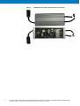
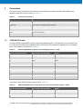
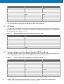
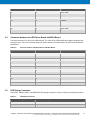
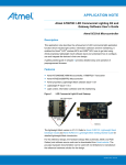
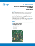
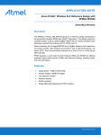
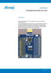
APPLICATION NOTE
AT03201: 100W Commercial LED Light with Wireless
Connection - Hardware User Guide
Atmel AVR XMEGA
Description
The reference design kit of 100W Commercial LED Light with Wireless Connection
is developed to demonstrate Lightweight Mesh (LwMesh) protocol function based
®
®
on the Atmel AVR ATmega256RFR2. The hardware includes three parts, AC to
DC power supply, Atmel single-chip RF MCU Control board, and LED drive circuit
based on Atmel AVR ATxmega8E5. The LED string is controlled by PC software
via the Lightweight Mesh protocol commands through the ATmega256RFR2. The
kit supports to LED on/off, and tunable brightness.
For this reference design, the hardware design files (schematic, BOM, and PCB
Gerber) and software source code can be downloaded from Atmel website. The
provided hardware documentation can be used with no limitations to manufacture
the reference hardware solution for the design.
Features
• Atmel AVR ATmega256RFR2 Microcontroller with 2.4GHz radio transceiver
• Atmel AVR ATxmega8E5 Microcontroller
• Drives four high power LED strings
• Up to 750mA current for each LED string with individual PWM
• Wide PWM dimming range with 16-bit solution
• Open and short LED string protection
• Replaceable LED strings
• 140W AC to DC power supply
• Time-dependent control for LED string
• One button for user
• One dual LED for user
• Program/Debug interface: JTAG, PDI
Atmel-42302A-100W-Commercial-LED-Light-with-Wireless-Connection-HW-User-Guide-ApplicationNote_052014
Figure 1.
2
100W Commercial LED Light with Wireless Connection
AT03201: 100W Commercial LED Light with Wireless Connection – Hardware User Guide [APPLICATION NOTE]
Atmel-42302A-100W-Commercial-LED-Light-with-Wireless-Connection-HW-User-Guide-ApplicationNote_052014
1
Related Items
The following list contains links to the most relevant documents for the 100W Commercial LED Light with
Wireless Connection.
2
•
Atmel MCU Wireless ATmega256RFR2/ ATmega128RFR2/ ATmega64RFR2 Summary Datasheet
The document contains complete and detailed description of all modules included in the Atmel MCU
wireless microcontroller family.
•
Atmel MCU Wireless ATmega256RFR2/ ATmega128RFR2/ ATmega64RFR2 Datasheet
ATmega256RFR2 is the microcontroller used in this solution.
•
Atmel AVR10004: RCB256RFR2 – Hardware User Manual
The document describes the usage, design, and layout of the Atmel ATmega256RFR2 radio controller
board.
•
ATxmega32E5/ ATxmega16E5/ ATxmega8E5 Preliminary Datasheet
ATxmega8E5 is the microcontroller used in this solution.
•
Atmel AVR XMEGA MANUAL
The document contains complete and detailed description of all modules included in the Atmel AVR
XMEGA E microcontroller family.
•
AVR1612: PDI programming driver
The Program and Debug Interface (PDI) is an Atmel proprietary interface for external programming and
on-chip debugging of the device. This application note describes how to implement PDI programming.
•
Atmel Studio 6
Atmel Studio 6 is a free Atmel IDE for development of C/C++ and assembler code for Atmel
microcontrollers.
•
Atmel JTAGICE3
JTAGICE3 is a mid-range development tool for Atmel AVR 8- and 32-bit microcontrollers with on-chip
debugging for source level symbolic debugging, Nano Trace (if supported by the device) and device
programming.
®
Overview
The Atmel AVR 100W Commercial LED Light with Wireless Connection kit is intended to demonstrate the Atmel
AVR ATmega256RFR2 single-chip microcontroller and radio transceiver which is used in the LED Lighting
application via Lightweight Mesh protocol; the two Atmel AVR ATxmega8E5 devices are used as the LED driver.
The ATmega256RFR2 communicate with ATxmega8E5 via TWI bus.
The kit can drive four individual parallel high power LED Strings. Each String can output 850mA under 38V, so
the general output power can reach over 100W. The LED string can be controlled individually by PWM signal; it
can easily realize the on/off and tunable brightness. The control commands come from the PC software via
wireless communication.
The kit includes three boards: Power Supply Board, MCU Control Board, and LED Drive Board.
Power Supply Board contains two AC to DC switching power supplies, one dedicates for four parallel high power
LED strings, and it provides 40V up to 3.5A. Another is standby power for MCUs, and it provides 12V/100mA and
-6V/20mA.
MCU Control Board contains the MCU ATmega256RFR2, RF signal amplifier, antenna, 8-megabit data flash,
and trickle charge timekeeping chip. The ATmega256RFR2 in charge of the communication between the kit and
PC software, and communicate with the LED Driver board to control the LED String by TWI bus.
LED Driver Board is configured as two ATxmega8E5 devices, and four parallel LED drive circuits. The four LED
Strings divided into two groups, one ATxmega8E5 control two of them.
AT03201: 100W Commercial LED Light with Wireless Connection – Hardware User Guide [APPLICATION NOTE]
Atmel-42302A-100W-Commercial-LED-Light-with-Wireless-Connection-HW-User-Guide-ApplicationNote_052014
3
Figure 2-1 shows the available features on the MCU control board.
Figure 2-1.
Overview of the MCU Control Board of the Kit
Figure 2-2 shows the available features on the LED Drive board.
Figure 2-2.
4
Overview of the LED Drive Board of the Kit
AT03201: 100W Commercial LED Light with Wireless Connection – Hardware User Guide [APPLICATION NOTE]
Atmel-42302A-100W-Commercial-LED-Light-with-Wireless-Connection-HW-User-Guide-ApplicationNote_052014
Figure 2-3 shows the available features on the Power Supply board.
Figure 2-3.
2.1
Overview of the Power Supply Board of the Kit
Components for Setup
The components in Table 2-1 are necessary to perform all functions of the kit.
Table 2-1.
Components for Kit Setup
Component
Function
Kit
The kit assembled with Power Supply Board, MCU Control Board,
and LED Driver Board
AC Power line
Supply 110V/220VAC and 50/60Hz frequency power to the kit
Four LED Strings
If=1A, 28V≤Vf≤38V@If=1A
As a load for kit
Programming Tool with JTAG and PDI interface
Debug and Programming
ZLL/Ethernet Gateway
Communicate the kit and Wi-Fi Router
Wi-Fi Router
Communicate the Tablet or Smartphone and ZLL/Ethernet Gateway
Personal Computer
Control the kit using Personal Computer software
Application Software
Running on the Personal Computer to control the kit
AT03201: 100W Commercial LED Light with Wireless Connection – Hardware User Guide [APPLICATION NOTE]
Atmel-42302A-100W-Commercial-LED-Light-with-Wireless-Connection-HW-User-Guide-ApplicationNote_052014
5
2.2
Programming Firmware
The Atmel ATmega256RFR2 and ATxmega8E5 on the kit are programmed with the default firmware. The
detailed description of the firmware is available in the Atmel AT06700: LED Commercial Light Kit and Gateway
Software User Manual.
2.3
Power Supply
The kit is powered by AC line under the voltage range 85V to 264V with 50/60Hz frequency. The AC to DC
switching power supply can deliver 40V/3.5A, 12V/100mA, and -6V/20mA.
The 40V supplies to LED strings. The 12V and -6V supply power to LED driver circuit. The 12V is also regulated
down to 3.3V by an onboard DC-DC regulator, which provides power to the MCUs on MCU Control Board and
LED Drive Board.
Note:
2.4
In this application, the ATxmega8E5 devices are running under 32MHz, according to the datasheet of
the ATxmega8E5, the VCC of ATxmega8E5 needs greater than 2.7V.
Programming the Kit
The ATmega256RFR2 on the kit can be programmed by programming tools through the JTAG interface.
The ATxmega8E5 on the kit can be programmed through the PDI interface.
6
AT03201: 100W Commercial LED Light with Wireless Connection – Hardware User Guide [APPLICATION NOTE]
Atmel-42302A-100W-Commercial-LED-Light-with-Wireless-Connection-HW-User-Guide-ApplicationNote_052014
3
Connectors
The 100W Commercial LED Light with Wireless Connection kit has several connectors and headers which
dedicate for difference purpose, shown in Table 3-1.
Table 3-1.
3.1
Connector and Functions
Connector
Function
J701
JTAG/UART interface for programming and debug
J702,J703
PDI interface for programming and debug
J704, J705
Connector between the Power Supply Board and LED Driver Board
J706, J712
Connector the LED Driver Board and MCU Board
J707
AC source connector
CN401,CN402,CN501,CN502
LED Strings Connector
JTAG/UART Header
The Atmel AVR ATmega256RFR2 can be programmed and debugged via JTAG interface. Any tools which carry
the JTAG interface can program and debug the kit. JTAGICE3 is recommended for programming. The definition
of the JTAG interface can be found in Table 3-2.
Table 3-2.
AVR ATmega256RFR2 Programming and Debugging Interface – JTAG
Pin on programming header
Pin on AVR ATmega256RFR2
JTAG
1
PF4
TCK
2
-
GND
3
PF6
TDO
4
-
VCC
5
PF5
TMS
6
RSTN
nSRST
7
-
-
8
-
-
9
PF7
TDI
10
-
GND
The definition of the UART interface can be found in Table 3-3.
Table 3-3.
AVR ATmega256RFR2 Universal Asynchronous Receiver/Transmitter Interface – UART
Pin on programming header
Pin on AVR ATmega256RFR2
UART
1
-
-
2
-
GND
3
-
-
AT03201: 100W Commercial LED Light with Wireless Connection – Hardware User Guide [APPLICATION NOTE]
Atmel-42302A-100W-Commercial-LED-Light-with-Wireless-Connection-HW-User-Guide-ApplicationNote_052014
7
Pin on programming header
Pin on AVR ATmega256RFR2
UART
4
-
VCC
5
-
-
6
-
-
7
PE0
RXD
8
PE1
TXD
9
-
-
10
-
-
The JTAG and UART interface uses the different pins at the same header J701.
3.2
PDI Header
The Atmel AVR ATxmega8E5 devices can be programmed and debugged via PDI header. Any tools which carry
the PDI interface can program and debug the kit. JTAGICE3 is recommended for programming. The definition of
the PDI interface can be found in Table 3-4.
Table 3-4.
3.3
AVR ATxmega8E5 Programming and Debugging Interface – PDI
Pin on programming header
PDI
1
DATA
2
VCC
3
-
4
-
5
CLK
6
GND
Connector between the Power Supply Board and LED Driver Board
The female connector J704 is lie on the Power Supply Board. The male J705 is lie on the LED Driver Board. The
Power Supply Board provides the power to the LED Driver Board via the connector pair.
Table 3-5.
8
Connector between Power Supply Board and LED Driver Board
Pin on J704
Pin on J705
Name on the connector
1
16
-
2
15
-
3
14
-12VDC
4
13
Control the relay ON or OFF
5
12
+12VDC
6
11
-
7
10
GND for DC to DC circuit
8
9
-
AT03201: 100W Commercial LED Light with Wireless Connection – Hardware User Guide [APPLICATION NOTE]
Atmel-42302A-100W-Commercial-LED-Light-with-Wireless-Connection-HW-User-Guide-ApplicationNote_052014
3.4
Pin on J704
Pin on J705
Name on the connector
9
8
Power GND
10
7
Power GND
11
6
+40VDC
12
5
+40VDC
13
4
+40VDC
14
3
+40VDC
15
2
Power GND
16
1
Power GND
Connector between the LED Driver Board and MCU Board
The male connector J712 is lie on the MCU Board. The J706 on the LED Drive Board needs to assemble any
connector into it. The J712 connector plugs into J706 to achieve connect between the LED Driver Board and
MCU Board.
Table 3-6.
3.5
Connector between LED Driver Board and MCU Board
Pin on J706
Pin on J712
Name on the connector
1
11
GND
2
12
TWI_SCL
3
9
VIN_3V3
4
10
TWI_SDA
5
7
-
6
8
-
7
5
-
8
6
-
9
3
-
10
4
-
11
1
-
12
2
Control the Relay ON or OFF
LED Strings Connector
The CN401, CN402, CN501, and CN502 are LED strings connectors. These connectors are polarity sensitive.
Table 3-7.
LED Strings Connector
Pin on LED Strings Connector
Name on LED Strings Connector
1
LED String+
2
LED String-
AT03201: 100W Commercial LED Light with Wireless Connection – Hardware User Guide [APPLICATION NOTE]
Atmel-42302A-100W-Commercial-LED-Light-with-Wireless-Connection-HW-User-Guide-ApplicationNote_052014
9
4
Peripherals
Figure 4-1 shows the system block diagram of the 100W Commercial LED Light with Wireless Connection kit.
Figure 4-1.
100W Commercial LED Light with Wireless Connection System Block Diagram
The kit has high voltages on the board that can pose a shock hazard to the user.
Appropriate care should be taken when operating the board. In addition to the high power LED
strings are used to LED Load. Do not look directly at the LED strings when the kit is active and/or
protect your eyes with dark glasses since the LED strings are very bright.
To turn on the kit, simply plug the power cord into an AC socket which applies the 85V to 264V and 50/60Hz
frequency power source. The LED strings will light up while the kit is powered.
4.1
AC to DC Switching Power Supply
In the system, there are two AC to DC switching power supplies. One is dedicate for LED strings, and the other is
standby power supply for MCUs. The standby power supply is used for getting low static power (low than 0.3W).
These two power supplies share one filter circuit. Figure 4-2 shows the diagram of the AC to DC switching power
supply.
Figure 4-2.
10
AC to DC Power Supply System Block Diagram
AT03201: 100W Commercial LED Light with Wireless Connection – Hardware User Guide [APPLICATION NOTE]
Atmel-42302A-100W-Commercial-LED-Light-with-Wireless-Connection-HW-User-Guide-ApplicationNote_052014
The main power supply contains the Power Factor Correction (PFC) circuit, device FA5612 works as the PFC
converter in this application which makes the power factor value better than 99% with the rated load and rated
input AC voltage. The rectification voltage of the AC input voltage will boost to 400VDC.
The FA5641 is a quasi-resonant type switching power supply control IC with excellent standby-by characteristics.
The main power supply uses a secondary-side control technology by opto-isolated feedback for getting precise
output voltage. It also works at the fixed-frequency Discontinuous Conduction Mode operation at heavy load, and
switches to variable frequency operation at light load for obtaining maximum efficiency.
The main power supply provides 40V/3.5A for LED Strings, and input voltage range is 85V to 264VAC with
50/60Hz frequency. The efficiency is more than 89% with the rated output load and rated input AC voltage.
About the standby power supply, the iw1706 is used to PWM controller. The standby power supply uses a
primary-side control technology to eliminate the opto-isolated feedback and secondary regulation circuits
required in traditional designs.
The standby power supply works at the fixed-frequency Discontinuous Conduction Mode (DCM) under heavy
load, and switches to variable frequency operation under light load to get the maximum efficiency. In other words,
it uses adaptive multi-mode PWM/PFM control to dynamically change the BJT switching frequency for efficiency
and EMI.
The standby power supply provides 12V/100mA and -6V/20mA for system.
The main power supply and standby power supply are also build-in fault protection features include overvoltage
protection (OVP), output short circuit protection (SCP), and over-current protection (OCP).
4.2
BUCK LED Driver
Buck converter and linear driver are used to drive LED strings. Figure 4-3 shows the diagram of the BUCK LED
driver.
Figure 4-3.
Diagram of BUCK LED Driver
In the Buck converter, the Atmel ATxmega8E5 MCU generates the fixed 50kHz PWM to drive Q1 MOSFET, and
the Buck converter output proper voltage for LED string. When MCU detected the voltage at the Drain of the Q2
AT03201: 100W Commercial LED Light with Wireless Connection – Hardware User Guide [APPLICATION NOTE]
Atmel-42302A-100W-Commercial-LED-Light-with-Wireless-Connection-HW-User-Guide-ApplicationNote_052014
11
more than 0.3V, the MCU will immediately turn off the PWM signal, and then turn off the Q1 MOSFET. So the
voltage of the C1 will turn down until the voltage at the Drain of the Q2 less than 0.3V and then turn on Q1
MOSFET to provide power for LED string. This process is immediately achieved by on-chip hardware modules linking the Event System Controller module to the Fault Extension module in the Atmel ATxmega8E5.
In the Buck Converter circuit, the response speed of the Q1 MOSFET should be as fast as possible, and delay
time should be as short as possible between the PWM output of the MCU and the drive of the Q1 MOSFET. So
the accelerating circuit is needed in the BUCK Converter.
The linear driver is used to drive LED string current for dimming. The ATxmega8E5 MCU generates the fixed
60kHz PWM to drive external N-CH MOSFET Q2. The R1 and C2 consist of low pass filter. The U1 operational
amplifier is consisted of negative feedback circuit. The R1 and R2 consisted of voltage division circuit. So the R1,
R2, C2, U1, and Q2 consisted of the linear constant current source.
Suppose the value of the RS and maximum current of the LED String, the user can turn the value of R1 and R2 to
set the maximum current of the LED String from the hardware design. The relationship between the R1 and R2
as below:
IMAX × RS = (VCC/(R1+R2)) × R2
After rearrange and substitute:
R1 = (VCC × R2)/(IMAX × RS) - R2
IMAX is the maximum current of the LED string. In the design, considering the type of the LED string used in this
reference design, the IMAX is set to be 850mA.
RS is the sample resistance
VCC is the power supply of the MCU device
In the design, considering the type of the LED string used in this reference design, the maximum LED string
current is set to be 850mA, and suppose RS is 0.15Ω. When MCU detected the voltage at the Source of the Q2
beyond 0.12V, the MCU will immediately turn off the Q2 MOSFET until the voltage at the Source of the Q2 less
than 0.12V, then the ATxmega8E5 will turn on Q2 MOSFET again to provide power road for LED string.
Table 4-1.
Pin on AVR ATxmega8E5
Buck Circuit PWM
PC5
PWM signal for one BUCK circuit
PC4
PWM signal for another BUCK circuit
Table 4-2.
Linear Driver of the LED Connection
Pin on AVR ATxmega8E5
Linear Driver
PD4
PWM signal for one Linear constant current source
PD5
PWM signal for another Linear constant current source
Table 4-3.
12
Buck Circuit PWM Connection
Measure Function in the Buck and Linear Driver Circuit Connection
Pin on AVR ATxmega8E5
Measure Function of the circuit
PA0
Measure the input voltage of another LED String
PA1
Measure the input voltage of one LED String
AT03201: 100W Commercial LED Light with Wireless Connection – Hardware User Guide [APPLICATION NOTE]
Atmel-42302A-100W-Commercial-LED-Light-with-Wireless-Connection-HW-User-Guide-ApplicationNote_052014
Pin on AVR ATxmega8E5
Measure Function of the circuit
PA3
Measure the output voltage of another LED String
PA4
Measure the output voltage of one LED String
PA5
Measure the current of one LED String
PD7
Measure the current of another LED String
The Atmel ATxmega8E5 device is debugged and programmed via PDI interface.
Table 4-4.
PDI Interface Connection
Pin on AVR ATxmega8E5
PDI Header
PDI
PDI
/RESET
PCK
For more information about the buck circuit, see the application note Atmel AT04204: Design a Buck circuit with
XMEGA E.
The ATxmega8E5 device communicates with ATmega256RFR2 via TWI bus.
Table 4-5.
4.3
TWI Interface Connections
Pin on AVR ATxmega8E5
Pin on AVR ATmega256RFR2
TWI Interface
PC0
PD1
TWI_SDA
PC1
PD0
TWI_SCL
RF Transceiver
The Atmel AVR ATmega256RFR2 device integrates a high performance RF-CMOS 2.4GHz radio transceiver.
To get the RF function, only four components are needed; ATmega256RFR2, Balun, Capacitance, and Antenna.
Figure 4-4.
RF Function Circuit
Antenna
RFP
ATmega256RFR2
B
C1
RFN
PCB layout is quite important for the high RF performance.
The application note Atmel AVR10004: RCB256RFR2 – Hardware User Manual will guide you how to design the
RF PCB.
In order to expand transmission distance, a Power Amplifier (PA) circuit is added into the system. The user can
choose whether to use the PA function via soldering cap C2, C3 and removing cap C1.
AT03201: 100W Commercial LED Light with Wireless Connection – Hardware User Guide [APPLICATION NOTE]
Atmel-42302A-100W-Commercial-LED-Light-with-Wireless-Connection-HW-User-Guide-ApplicationNote_052014
13
Figure 4-5.
RF with PA Function Circuit
RFP
ATmega256RFR2
Table 4-6.
4.4
Antenna
C1
B
C2
RFN
C3
PA
Circuit
Power Amplifier Connection
Pin on ATmega256RFR2
Power amplifier
PG0
CTX
PG1
ANT_SET
PG2
CPS
PD7
CSD
Trickle Charge Timekeep
In this reference design, use the DS1302 trickle charge timekeeping chip to wake up the Atmel
ATmega256RFR2 when it is under the sleeping by time. It provides seconds, minutes, hours, days, date, month,
and year information to ATmega256RFR2. The DS1302 has dual power for primary and back-up power supplies.
The battery is used to back-up power, and it can be charged by primary power while the kit is working. DS1302
communicates with the ATmega256RFR2 via a simple serial interface.
Table 4-7.
4.5
Simple Serial Interface Connection
Pin on DS1302
Pin on AVR ATmega256RFR2
SCLK
PD4
I/O
PD5
CE
PD6
DataFlash
The Serial Peripheral Interface (SPI) sequential access flash memory Atmel AT45DB081D is optional for user to
storing any application data needed.
Table 4-8.
14
Serial Peripheral Interface Connection
Pin on AVR ATmega256RFR2
Simple serial interface
PB0
SSN
PB1
SCK
PB2
MOSI
AT03201: 100W Commercial LED Light with Wireless Connection – Hardware User Guide [APPLICATION NOTE]
Atmel-42302A-100W-Commercial-LED-Light-with-Wireless-Connection-HW-User-Guide-ApplicationNote_052014
4.6
Pin on AVR ATmega256RFR2
Simple serial interface
PB3
MISO
RSTN
nRST
Function Button (not mounted)
The design is equipped with one function button for user.
Table 4-9.
4.7
Function Button Connection
Pin on AVR ATmega256RFR2
Function Button
PE2
INT_BUTTON
LED Indicator (not mounted)
The design is equipped with one dual LED (Red and Green) available on the board that can be used to indicate
the working condition of the kit. The green LED and the red LED can be individually activated by driving the
connected I/O line to VCC. The dual LED can also emit orange light when both red and green LEDs are activated.
Table 4-10.
4.8
LED Connection
Pin on AVR ATxmega32E5
LED
PD2
Red LED
PD3
Green LED
Temperature Sensor (not mounted)
The design is equipped with one temperature sensor (NCP18WF104FR). The power is supplied by VCC 3.3V.
The ADC reference is 1.6V. R1 is series with the NTC to ensure the input voltage does not exceed the ADC input
range.
The NTC sense voltage could be got from the following equation:
VSENSE = (VCC×RTH1) ÷ (R1+RTH1)
For MCU, the equation for the ADC decimal code is:
ADC Code = 4095 × (VSENSE ÷ 1.6)
Figure 4-6.
Temperature Sensor Circuit
Vcc
Vsense
C1
R1
RTH1
AT03201: 100W Commercial LED Light with Wireless Connection – Hardware User Guide [APPLICATION NOTE]
Atmel-42302A-100W-Commercial-LED-Light-with-Wireless-Connection-HW-User-Guide-ApplicationNote_052014
15
Table 4-11.
NTC Table
Part number:
NCP18WF104F
Resistance:
100kΩ ±1%
B-constant:
4200k
Temperature [°C]
Resistance [kΩ]
Temperature [°C]
Resistance [kΩ]
-40
4205.686
45
41.336
-35
2966.436
50
33.628
-30
2118.789
55
27.510
-25
1531.319
60
22.621
-20
1118.422
65
18.692
-15
825.570
70
15.525
-10
615.526
75
12.947
-5
463.104
80
10.849
0
351.706
85
9.129
5
269.305
90
7.713
10
207.891
95
6.546
15
161.722
100
5.572
20
126.723
105
4.764
25
100.000
110
4.087
30
79.222
115
3.518
35
63.509
120
3.040
40
51.084
125
2.634
Table 4-12.
Temperature Sensor Connection
Pin on AVR ATxmega256RFR2
Temperature sensor
PF1
NTC_SENSE
The design is equipped with one light sensor TEMT6000. Thermostat can enable or disable the backlight based
on the ambient light strength. The ADC reference is internal 1.6V.
The sense voltage can be found from the following equation:
-6
VSENSE = ICA × 10 × R1
ICA is Collector Light Current.
16
AT03201: 100W Commercial LED Light with Wireless Connection – Hardware User Guide [APPLICATION NOTE]
Atmel-42302A-100W-Commercial-LED-Light-with-Wireless-Connection-HW-User-Guide-ApplicationNote_052014
Figure 4-7.
Light Sensor Circuit
Vcc
TEMT6000
R1
C1
Figure 4-8.
The Curve of Collector Light Current vs. Ambient Illuminance
Table 4-13.
The Sense Voltage vs. Illuminance
Illuminance
[lx]
Current
[µA]
VSENSE
[V]
Illuminance
[lx]
Current
[µA]
VSENSE
[V]
Illuminance
[lx]
Current
[µA]
VSENSE
[V]
10
5.0
0.050
75
37.5
0.375
140
70.0
0.700
15
7.5
0.075
80
40.0
0.400
145
72.5
0.725
20
10.0
0.100
85
42.5
0.425
150
75.0
0.750
25
12.5
0.125
90
45.0
0.450
155
77.5
0.775
30
15.0
0.150
95
47.5
0.475
160
80.0
0.800
35
17.5
0.175
100
50.0
0.500
165
82.5
0.825
40
20.0
0.200
105
52.5
0.525
170
85.0
0.850
45
22.5
0.225
110
55.0
0.550
175
87.5
0.875
50
25.0
0.250
115
57.5
0.575
180
90.0
0.900
55
27.5
0.275
120
60.0
0.600
185
92.5
0.925
60
30.0
0.300
125
62.5
0.625
190
95.0
0.950
65
32.5
0.325
130
65.0
0.650
195
97.5
0.975
70
35.0
0.350
135
67.5
0.675
200
100.0
1.000
AT03201: 100W Commercial LED Light with Wireless Connection – Hardware User Guide [APPLICATION NOTE]
Atmel-42302A-100W-Commercial-LED-Light-with-Wireless-Connection-HW-User-Guide-ApplicationNote_052014
17
Table 4-14.
4.9
Temperature Sensor Connection
Pin on AVR ATxmega256RFR2
Light sensor
PF0
LIGHT_SENSE
LED String Power Control
In order to reduce the power consumption when turn off the LED Strings, the main switching power supply should
be turn off.
Table 4-15.
18
LED String Power Control Connection
Pin on AVR ATxmega256RFR2
LED String Power Control
PE7
LED_POWER_CT
AT03201: 100W Commercial LED Light with Wireless Connection – Hardware User Guide [APPLICATION NOTE]
Atmel-42302A-100W-Commercial-LED-Light-with-Wireless-Connection-HW-User-Guide-ApplicationNote_052014
5
Code Examples
The example application is based on the Atmel Software Framework that is included in Atmel Studio 6. The Atmel
Software Framework can also be found as a separate package online at:
http://www.atmel.com/tools/avrsoftwareframework.aspx.
For more information about the code example, see the application note Atmel AT06700: LED Commercial Light
Kit and Gateway Software User Manual.
AT03201: 100W Commercial LED Light with Wireless Connection – Hardware User Guide [APPLICATION NOTE]
Atmel-42302A-100W-Commercial-LED-Light-with-Wireless-Connection-HW-User-Guide-ApplicationNote_052014
19
6
Revision History
Doc Rev.
42302A
20
Date
05/2014
Comments
Initial document release.
AT03201: 100W Commercial LED Light with Wireless Connection – Hardware User Guide [APPLICATION NOTE]
Atmel-42302A-100W-Commercial-LED-Light-with-Wireless-Connection-HW-User-Guide-ApplicationNote_052014
Atmel Corporation
1600 Technology Drive, San Jose, CA 95110 USA
T: (+1)(408) 441.0311
F: (+1)(408) 436.4200
│
www.atmel.com
© 2014 Atmel Corporation. / Rev.:Atmel-42302A-100W-Commercial-LED-Light-with-Wireless-Connection-HW-User-Guide-ApplicationNote_052014.
Atmel®, Atmel logo and combinations thereof, AVR®, Enabling Unlimited Possibilities®, XMEGA®, and others are registered trademarks or trademarks of Atmel
Corporation in U.S. and other countries. Other terms and product names may be trademarks of others.
DISCLAIMER: The information in this document is provided in connection with Atmel products. No license, express or implied, by estoppel or otherwise, to any intellectual property right
is granted by this document or in connection with the sale of Atmel products. EXCEPT AS SET FORTH IN THE ATMEL TERMS AND CONDITIONS OF SALES LOCATED ON THE ATMEL
WEBSITE, ATMEL ASSUMES NO LIABILITY WHATSOEVER AND DISCLAIMS ANY EXPRESS, IMPLIED OR STATUTORY WARRANTY RELATING TO ITS PRODUCTS INCLUDING,
BUT NOT LIMITED TO, THE IMPLIED WARRANTY OF MERCHANTABILITY, FITNESS FOR A PARTICULAR PURPOSE, OR NON-INFRINGEMENT. IN NO EVENT SHALL ATMEL BE
LIABLE FOR ANY DIRECT, INDIRECT, CONSEQUENTIAL, PUNITIVE, SPECIAL OR INCIDENTAL DAMAGES (INCLUDING, WITHOUT LIMITATION, DAMAGES FOR LOSS AND
PROFITS, BUSINESS INTERRUPTION, OR LOSS OF INFORMATION) ARISING OUT OF THE USE OR INABILITY TO USE THIS DOCUMENT, EVEN IF ATMEL HAS BEEN ADVISED
OF THE POSSIBILITY OF SUCH DAMAGES. Atmel makes no representations or warranties with respect to the accuracy or completeness of the contents of this document and reserves
the right to make changes to specifications and products descriptions at any time without notice. Atmel does not make any commitment to update the information contained herein. Unless
specifically provided otherwise, Atmel products are not suitable for, and shall not be used in, automotive applications. Atmel products are not intended, authorized, or warranted for use
as components in applications intended to support or sustain life.
SAFETY-CRITICAL, MILITARY, AND AUTOMOTIVE APPLICATIONS DISCLAIMER: Atmel products are not designed for and will not be used in connection with any applications where
the failure of such products would reasonably be expected to result in significant personal injury or death (“Safety-Critical Applications”) without an Atmel officer's specific written consent.
Safety-Critical Applications include, without limitation, life support devices and systems, equipment or systems for the operation of nuclear facilities and weapons systems. Atmel products
are not designed
nor intended
for use
in military or aerospace
applications
environments
unless specifically
designated by User
Atmel asGuide
military-grade.
Atmel products are
not designed nor
AT03201:
100W
Commercial
LED Light
withorWireless
Connection
– Hardware
[APPLICATION
NOTE
intended for use in automotive applications unless specifically designated
by Atmel as automotive-grade.
Atmel-42302A-100W-Commercial-LED-Light-with-Wireless-Connection-HW-User-Guide-ApplicationNote_052014
]
21