1
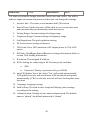
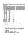
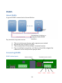
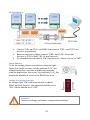
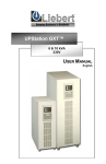
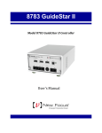
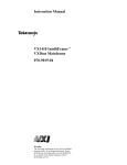
Grid-Tie PV INVERTER PV-5000W-HV Installation & Operation Manual Table of Contents Contact Information ..................................................................... 6 Warranty Information .................................................................. 7 PV System .................................................................................... 8 Product Overview ......................................................................... 9 Outline & Dimensions ...................................................................................................................9 Specification Label ...................................................................................................................... 10 Installation ................................................................................. 11 Inside the package ....................................................................................................................... 11 Assembly Chart ............................................................................................................................. 12 Choosing proper location ......................................................................................................... 13 Mounting Properly ...................................................................................................................... 14 Direction ...................................................................................................................................... 14 Keeping Clearance ................................................................................................................... 14 Mounting Procedure................................................................................................................... 15 Dimension of bracket ............................................................................................................. 15 Assembly bracket ..................................................................................................................... 15 Mounting bracket .................................................................................................................... 15 Attaching inverter ................................................................................................................... 16 Checking ...................................................................................................................................... 16 Wire Connections ........................................................................................................................ 16 Opening front cover ................................................................................................................ 16 Overview of Connection Area .............................................................................................. 16 AC wiring ..................................................................................................................................... 17 RS485, RJ45 and other connections .................................................................................. 19 Connect GFCI Buzzer & RCR (Optional) .......................................................................... 19 Connected with Ripple Control Receiver Interface (Optional)............................... 20 Closing the Front Cover ......................................................................................................... 20 Applicable PV module type ................................................................................................... 20 DC (PV) wiring .......................................................................................................................... 21 Unplugging PV .......................................................................................................................... 22 Ready to start ................................................................................................................................ 24 Check List .................................................................................................................................... 24 Changing the Grid-Connection and Operation Parameters .................................... 24 Start-up procedure .................................................................................................................. 25 1 Operation ................................................................................... 26 Overview.......................................................................................................................................... 26 LCD ................................................................................................................................................ 26 Icons on LCD .............................................................................................................................. 26 Touch Tab ................................................................................................................................... 27 Icons on Tab ............................................................................................................................... 27 Status LED .................................................................................................................................. 27 Clock Setting .................................................................................................................................. 27 Frames .............................................................................................................................................. 29 Operation Chart ........................................................................................................................ 29 Home Screen & Daily Frame ................................................................................................ 30 Monthly Frame.......................................................................................................................... 30 Daily Error Frame ................................................................................................................... 30 Operation Frame ...................................................................................................................... 31 Error Frame ............................................................................................................................... 31 E-Series (Optional)……………………………………………………………………………………35 Network and Internet ................................................................................................................ 46 Accessing inverter in a LAN (Local Area Network) .................................................... 46 Accessing inverter via Internet ........................................................................................... 46 Using USB ........................................................................................................................................ 47 Plug in USB stick....................................................................................................................... 47 Downloading data ................................................................................................................... 47 Firmware Upgrade .................................................................................................................. 48 Setting PF and 70% power limit ........................................................................................ 48 Capacity of Memory ................................................................................................................ 48 Browsing inverter WEB ............................................................................................................ 48 Basics ............................................................................................................................................ 48 Overview ...................................................................................................................................... 49 Settings ........................................................................................................................................ 49 RCR Setting Information ....................................................................................................... 52 RS485 ......................................................................................... 53 About RS485 .................................................................................................................................. 53 Connecting RS485 ....................................................................................................................... 53 RS485 related parts ................................................................................................................ 53 Wiring Diagram ....................................................................................................................... 54 Setup Address ............................................................................................................................ 54 Setting the terminal resistor ............................................................................................... 54 2 Connecting to Ripple Control Receiver (RCR) ............................... 55 Connection with single inverter ......................................................................................... 55 Connection with multiple inverters .................................................................................. 55 Maintenance .............................................................................. 57 Normal Maintenance .................................................................................................................. 57 Trouble Shooting ........................................................................ 58 Specifications ............................................................................. 59 Addendum ................................................................................. 61 Efficiency Chart............................................................................................................................. 61 PV-5000W-HV ........................................................................................................................... 61 3 Safety Precautions Before starting your journey, please read the following safety instructions carefully. Risk of Electric Shock Alternating Current (AC) and Direct Current (DC) sources are connected to this device. To prevent risk of electric shock during maintenance or installation, please ensure that all AC and DC connections are disconnected. Dangers! High voltage inside inverter can cause Electric shock, even when inverter is not operating. Wait for 41 minute before opening it. Warning! If the PV inverter is used in a manner that is not covered by the scope of warranty, the protection provided by the PV inverter may be impaired. Warning! A high DC voltage exists inside the inverter once PV module is exposed to the Sun, even if PV inverter is not working. PV modules ONLY! Designed for PV and solar power conversion only; do not use it for other DC sources and conversion. Grounding PV modules To make sure personal and system safety, please connect frame of PV modules to earth. Please also refer to requirements of local regulation. 4 Cautions! Do not stay permanently at a distance of less than 30 cm to the inverter. Inverter generates electromagnetic radiation could be harmful in such a close range. Hot Surface Some metallic parts of enclosure may be hot during operation. Recycle Do not throw this electronic device into the trash when discarding. To minimize pollution to environment, please handle as local regulations. 5 Contact Information PrimeVOLT Co., Ltd. 11F., No.211, Nanyang St., Xizhi Dist. New Taipei City 221, TAIWAN Telephone & FAX: TEL +886 2 26595388 FAX +886 2 26931009 Email: [email protected] 6 Warranty Information Warranty or liability will be void if damage caused by any, but not limited to the following: 1. 2. 3. 4. 5. 6. 7. 8. 9. Unauthorized opening of the unit Installation faults such as improper environment, wiring and application Working conditions beyond the unit specifications Improper operation of the unit Violation of safety instructions inside this manual Damage during transportation Any internal modification Replacing or installation of unauthorized software Unforeseen calamity or force majeure 7 PV System Switchboard PV Inverter PV Generator AC Output Public Grid Over-current Protection A typical PV system contains: 1. 2. 3. 4. 5. PV Generator (Panel): Receive sunlight and convert it into electricity Over-current Protection: A device such as breaker or fuse for DC overcurrent protection PV Inverter (with DC switch): Converts DC power from PV panels to AC output Switchboard: Connection from utility to inverter Public grid: Provides utility 8 Product Overview Outline & Dimensions PV-5000W-H V 9 Specification Label 10 Installation Inside the package Item Description A B C D E F G H Inverter Mounting Bracket Kit User Manual M4 Flat Screws X 4 for bracket Plastic Anchors & Screws × 3, and Metal anchor × 3 to fix bracket on wall Rubber Sealing for Ethernet, RS485, RCR and buzzer wires. M25 × 1, and M20 x 1 Insulated core end terminals: 4 mm2x 3, 6 mm2x 3 2 pairs of anchors and screws for buzzer installation (Optional) 11 Assembly Chart 12 Choosing proper location Avoid exposing the inverter in direct sunlight or with direct exposure to rain. 13 Mounting Properly Direction Keeping Clearance Mount the inverter in vertical direction; tilt or horizontal mounting should be avoided. 14 Mounting Procedure Dimension of bracket The bracket is used to support inverter on the wall. Before fixing it, refer to drilling location and dimensions below. Assembly bracket Before fixing, please assemble the bracket as below. Mounting bracket Place the assembled bracket where you want to. Drill at the correct positions, and fix bracket with the screws in the accessories. For safe and firm mounting, fix at least 3 points in a triangle position. 15 Attaching inverter 1. Lift inverter slightly higher than bracket; Make sure all fixing points on back are at the correct positions 2. Attach inverter on bracket 3. Hang inverter on bracket slowly 2 1 3 Fix with screws Checking 1. Check the 3 supporting points; make sure they are in their right positions 2. Lock caps are fixed with screws 3. Make sure inverter is well installed and secured on the wall At right position Wire Connections Opening front cover 1. Remove 4 screws on cover as shown in right figure 2. Take off the cover Overview of Connection Area 1. Cable Gland- AC cables 2. Cable Gland- Ethernet & RS485 cable 3. Cable Gland- Ripple Control receiver (RCR) 4. AC terminal block 5. RS485 terminal 16 6. 7. 8. 9. RS485 address selector RJ45 socket External GFCI Buzzer connector (reserved) Ripple Control receiver terminal 8 7 6 5 4 9 3 2 1 4 Independent AC circuit breaker needed An independent circuit breaker shall comply with local safety standards and codes, between inverter and grid BEFORE connecting. Make sure inverter can be safely disconnected from the grid in all circumstances. Use 30A/250V(PV-5000W-HV) circuit breaker. AC wiring 1. Prepare cables as table below Cross Section (mm2) 2.5 4 6 10 Maximum Length for 1% Loss (Meter) PV-5000W-HV 5 8 13 21 Table above is based on single-core copper wire with maximum temperature rise of 60°C. The actual wiring should be considered for following factors: Ambient temperature Wiring nearby Cooling 17 Please follow local standards if table above is different from. 2. 3. 4. Remove strip insulation ~ 7mm2 Remove sealing plug, twist off the AC cable gland Insert AC cable through M25 rubber sealing and hole 5. 6. Fix L (Line), N (Neutral) and PE ( ) on terminal block Twist cable gland to secure cable firmly 18 Note of selecting wire To safely secure cable on terminal block, please use solid wires. If stranded wires are used, apply core end terminals supplied in accessories. Torque Information The torque for AC terminal is between 0.6 ~0.8 Nm. RS485, RJ45 and other connections 1. Remove sealing plug, twist off the cable gland for RS485 2. Insert wires through bottom guidance, and hole of rubber sealing (M25) 3. Refer to RS485 section for proper connections 4. Connect RJ45 as figure below with the core bead 5. Twist related cable glands to secure cables firmly Connect GFCI Buzzer & RCR (Optional) The buzzer is used to notice user while internal GFCI (Ground Fault Current Interrupter, also known as RCMU, Residual Current Monitoring Unit) is active. To install, please 19 1. 2. 3. 4. Insert cord through the nut and connect to socket on inverter as figure below Attach and fix the buzzer on an indoor surface such as wall Connect buzzer with extension cord If the length of cord is not enough, please cut it and extend by similar cord to the length you need Place the buzzer where you can hear The buzzer will notice you in case of ground current fault. Place it near you. Do not put into a cabinet or place far away. Connected with Ripple Control Receiver Interface (Optional) Please refer to figure above for wiring. For further information, please refer to section ”Connecting to Ripple Control Receiver (RCR)”. External Buzzer RCR Terminal Closing the Front Cover After connecting all wires, please 1. 2. 3. Check all the connections again Close front cover, tighten 4 screws Check sealing in between cover and inverter Applicable PV module type Only non-grounding PV panel is applicable, user is suggested to consult with system installer for PV panel type selection. Warning Require PV modules that have IEC 61730 class A rating. 20 DC (PV) wiring 1. DC Input Rating Model Rating Max. Power (W) Max. DCV (V) Max. Current (A) String 2. PV-5000W-HV 5550 980 10 1 3. Use either of following connectors 1. Wieland PST40i1C (Preferred) 2. Multi-Contact MC4 (PV-KST4 & PV-KBT4) Select DC cables that can carry more than ISCPV (15A) in specification 4. Take off sealing plugs on connectors 5. Please plug in PV cables with recommended connectors to inverter as shown in figures 6. PV-5000W-HV PV1 (+) PV1 (-) Danger, Electric Shock! While working on DC wiring, ensure DC is completely turned off. 21 Polarity & voltage check Before plugging in, make sure the polarity and voltage are correct. Incorrect connections could cause malfunction. Over-Current protection at DC side As long as DC cables can carry more than 15A, you may not need over current protection device in installation. However, installers still have to check again to comply local safety standards and codes. Caution for parallel connections To connect PV in parallel, do not wire more than 1 strings for each MPP tracker except over-current protection device exists. Keep the sealing plugs in safe place Please keep those plugs in safe place. You may need to use them again in case removing DC connectors. Unplugging PV In case you need to disconnect the PV, follow the steps below: 1. 2. 3. 4. SWITCH OFF PV FIRST! Recommand to use Wieland assembling- / disconnecting tool Mounting tool PST (Art. No. 05.502.1753.0) Push interlock to release per figure below Pull off plugs 22 Be sure to SWITCH off PV Direct pull-off DC plugs cause dangerous spark. Be sure to switch off PV in advance. 23 Ready to start Check List Before starting the inverter, check following items: Item Mounting Point of check AC RS485 RJ45 Ripple Control receiver Checked? Inverter is firmly mounted on the bracket The 2 lock caps are secured Lock is closed All wires are firmly fixed on terminal block Polarity is correct Protective Ground is available Cable gland is tightened firmly All terminals are secured Polarity is correct Wires are tightened by cable gland If it is not used, the sealing plug is on the gland Front cover All screws are secured tightly The cover is firmly attached DC All plugs are firmly connected Polarity is correct Strings are not mixed-wiring (for multiple MPPT models) Changing the Grid-Connection and Operation Parameters If you need to change grid-connected setting and/or operation parameters including voltage, frequency, power factor and power limitation ranges, please contact with authorized personnel with authorized “USB key” and procedure to do that. After changing, to verify current setting, please swap to operation frame as indicated on page 31. 24 Start-up procedure Start No Check List & Settings? Yes Switch on AC. Wait for 30 seconds Switch off AC; check AC No LCD & Tab on? Yes Switch on PV (DC). Wait for 2 minutes Switch off PV; check PV No Producing power ? Yes Check Ethernet connection No Ethernet OK? Yes END 25 Operation Overview LCD Available Interface Date & Time Sun & PV panel AC Power Graph & Text Area Power Flow Hours or Days Energy Icons on LCD Icon Description USB. Appears while USB port is in use; flashing while accessing data RS485. Appears when there are data transferring via RS485 Wi-Fi. Appears while Wi-Fi dongle is connected. Refer to manual of Wi-Fi dongle Ethernet. Appears while Ethernet is connected Sun. Appears during daytime PV modules. Appears while PV is connected Utility. Appears while utility power is available Power feeding. Appears while inverter is feeding power 26 Note Touch Tab Touch Tab is used to change frame displayed on LCD Icons on Tab Description Icon Note Home. Switch back to Home Screen Toggle. Toggling between frames or information Backward. Switch to previous daily (monthly) frame Forward. Switch to next daily (monthly) frame Status LED This LED indicates the operation status by its color. In normal operation, it is green; in abnormal conditions that inverter is not working, it will show red. Clock Setting During the first installation where the internal clock has not been set, below frame automatically prompts user to set date and time. The flashing characters are the data to set. Use the touch tab to set. 27 While finished entering the new setting, tab settings. to finish and confirm the new The following table describes tab functions. Icon Function Note Confirm setting Switch data views among Year, Month, Day, Hour and Minute. Decrease number of settings Increase number of settings Incorrect Setting? In case of incorrect setting, after inverter starts, switch to “Information frame” to set again Keeping the Clock Setting In case where the AC power is disconnected for more than 3.5 hours, the internal clock will change back to the default settings. Clock Self-calibration If inverter is connected to Internet, the internal clock can synchronize with a local time server automatically. To do this, you need to set the time zone and timeserver via internal web server. Please refer to later sections. 28 Frames Operation Chart Note: Tab will go back to Home (Daily) Frame Daily Error Frame will not appear if there is no error in a day LAN IP and/or Wi-Fi IP will not appear if there is no Ethernet and/or Wi-Fi connected 29 Home Screen & Daily Frame The Home Screen (Daily Frame) shows the operation data of a day. The user can switch to different daily data by tapping FORWARD or BACKWORD. The date on the upper right side will change accordingly as well. Daily Yield Graph Date & Time Hours AC Power Peak Power Daily Yield Monthly Frame Display Month Monthly Yield Graph AC Power Day Monthly Yield Monthly PV peak The monthly Frame shows the operation data of a month. The user can switch to view a different monthly data by tapping FORWARD or BACKWORD. The month (shown on upper-right side) will change accordingly in the mean time. Daily Error Frame This frame exists when there were errors of operation during a day. 30 Error Count Error Type Operation Frame This frame shows the operation information of inverter. There are five subframes as below: 1. 2. 3. 4. 5. 6. E-Total & H-Total: Shows E-Total (Total accumulated Energy) in kWh and H-Total (Total operating hours of inverter) in hour LAN and Wi-Fi IP addresses: IP address information assigned to the inverter Clock setting: To set the clock of inverter. Refer to Clock Setting section Language setting: To select the language displayed on LCD Parameter Settings: Grid-Connection setting (VDE-AR-N 4105 or VDE 0126-1-1), 70% power limit status (ON or OFF) and PF setting (-0.8 ~ +0.8) System Info: F/W version Error Frame An error is an abnormal situation in the functioning of the solar system. The frame shows up automatically after detection of error. The second text line indicates error type. Error types are defined as table below: 31 Error Explanation AC VOLT HIGH Grid (AC) voltage is higher than the preset operation range AC VOLT LOW Grid (AC) voltage is lower than the preset operation range AC FREQ HIGH Grid frequency is higher than the preset operation range AC FREQ LOW Grid frequency is lower than the preset operation range PV VOLT HIGH PV voltage is higher than allowable voltage PV ISUL LOW The insulation resistance between either PV (+) or PV (-) to earth is lower 2M ohm GFC HIGH Ground Fault Current is higher than specification KEEP PV OFF Internal capacitor short, user has to switch off PV immediately FAN FAILS C1~ C7 Internal or External fan is abnormal, need to be checked. Reserved for internal recording 32 Note for “ KEEP PV OFF” On reading this message, please switch off DC switch of PV immediately. DO NOT turn it on again for any reason. Call immediately for service. Ground Fault Alarm In addition to showing „GFC HIGH“ on display, inverter will activate audiable alarm at optional buzzer and show message on web page while using a computer to monitor. 33 E-Series (Optional) E-Series stands for Economic Series. It offers three solutions for customers who are seeking only basic logger functionalities and wishing to save a bit upon their own interests. The display screen of inverter is either not equipped or of some simple form. Generally, E-Series contains no functionalities described in Ch.7, select functionalities in Ch.8, and no functionalities in Ch.9. LED Panel Only (Solution A) This is the simplest of E-Series. There is no screen of any kind. The LED panel has three LED lights and one button. When fault occurs, one or two or three LED lights will be on blinking. A B C Error Message OFF OFF OFF All Normal ON OFF OFF DC Current Injection High OFF ON OFF Relay Failed OFF OFF ON DC Current Sensor Failed A B C Error Message ON ON OFF High Internal Temperature ON OFF ON GFCI Detection Failed OFF ON ON Bus Failed ON ON ON Fan Failed 34 Blink Blink Blink Arcing Fault Detected (AFD) Blink OFF OFF Isolation Fault Blink Blink OFF Leakage Current High Note:Blinking means LEDs on for 0.5 secs and off for 0.5 secs. LED Panel + 7-Segment Display (Solution B) This is the optimal selection of E-Series between features and price. There is a screen consisted of 7 segments in addition to the LED panel from Ch.10.1. The LED panel has three LED lights and one button. When fault occurs, one or two or three LED lights will be on blinking. Stand-by Mode The 7-segment display screen enters stand-by mode when inverter receives no DC power coming from solar panels or internal communication fault occurs. The 7-segment display screen exits stand-by mode and goes to countdown mode when inverter receives sufficient DC power from solar panels again or internal communication fault gets resolved. 35 Countdown Mode When inverter is ready to connect to electrical grid, the 7-segment display screen enters a 300-second countdown. This is to notify user that inverter will be starting generating power soon. Regular Mode When inverter has connected to electrical grid and started generating power, of the 7-segment display screen enters regular mode. This mode carries and shows inverter numbers and messages with a 2-second interval between. The starting on-screen information by default is the cumulative solar power that has been generated today (unit: W). Push the button on LED panel once to make all inverter information rolled on 7-segment display screen in a sequence. Refer to the flow chart below for the sequence and on-screen inverter information. If there has been no error occurred, error message is not included in the sequence and will not be shown on 7-segment display screen. When the roll of sequence has completed, the on-screen figure will return to cumulative solar power that has been generated today (unit: W), which is where the flow began from. 36 Press Button 2sec 2sec 2sec 2sec 2sec 2sec 2sec Total Pac System Fac 2sec Tracker 1 Idc Phase R Vac 2sec Tracker 2 Idc Phase S Vac 2sec Phase T Vac 2sec Tracker 1 Vdc 2sec Tracker 2 Vdc 2sec Tracker 3 Vdc 2sec 37 Tracker 3 Idc Modbus address E-Today Firmware version Error massage Index 0. Indication Frequency of electrical grid Unit Hz 1. Voltage of electrical grid phase R V 2. Voltage of electrical grid phase S V 3. Voltage of electrical grid phase T V 4. Input voltage of DC tracker 1 V 5. Input voltage of DC tracker 2 V 6. Input voltage of DC tracker 3 V 7. Input current of DC tracker 1 A 8. Input current of DC tracker 2 A 9. Input current of DC tracker 3 A A. Designated network communication address E. Cumulative power generated today (E-Today) kWh Error Messages Error Message KEEP PV OFF Indication Internal fault detected Please keep DC breaker of solar panels off C1 High DC current detected C2 Relay failed C3 DC current sensor failed C4 Internal temperature high C5 GFCI detection failed C6 Bus Failed C7 Anti-islanding detection failed FAN FAILS Fan not working properly 38 Error Message F1 Indication Bus voltage low F2 Bus voltage high F3 CPU communication abnormal F4 Mismatch of firmware version between CPUs F5 EEPROM memory faulty F6 Error on system consistency F7 Over-current in inverter detected F8 Slow start-up on Bus Error Message E1 Indication Grid voltage over range E2 Grid voltage below range E3 Electrical grid not deteced E4 Grid voltage over range E5 Grid frequency below range E6 DC voltage from PV higher than limit E7 Check for insulation of solar panels failed E8 Leakage current high 39 LED Panel + LCM Panel (Solution C) This is the premium selection of E-Series. There is a LCM screen in addition to the LED panel from Ch.10.1. The LED panel has three LED lights and one button. When fault occurs, one or two or three LED lights will be on blinking. Pac Etoday 10000W 50.5kWh Welcome Mode The LCM screen enters welcome mode and notify of a 300-second countdown when inverter receives sufficient DC power coming from solar panels. Inverter will connect to electrical grid and start generating power when the 300-second countdown has completed. WELCOME Waiting 300s Regular Mode When inverter has connected to electrical grid and started generating power, of the LCM screen enters regular mode. The starting on-screen information by default is the solar power being generated at the moment (unit: W) and cumulative solar power that has been generated today (unit: kWh). Push the button on LED panel to change information display frame. Refer to the following table and flow chart for the sequence and on-screen inverter information. 40 WELCOME Waiting 300s 5sec Pac Etoday 10000W 50.5kWh Press Button Vac 220/221/222V Iac 15/16/17A Press Button Vdc 580/590/600V Idc 12/13/14A Press Button Etotal Htotal 1799kWh 572hr Press Button PV-10000T-U Ver 01.01.01 Press Button Modbus ADDR. 1 Press Button AC VOLT HIGH Vac 271V 41 Error Mode When inverter encounters an error, LCM screen enter error mode and an error message will be displayed on LCM screen continuously. AC VOLT HIGH Vac 271V This error message will remain on-screen until user presses the button on LED panel to unlock and exit error mode. When exited, the LCM screen returns to regular mode and goes to the information frame displaying the solar power being generated at the moment (unit: W) and cumulative solar power that has been generated today (unit: kWh). The error message mentioned above will be recorded in Last ERROR information frame. Refer to the table below for interpretation of all inverter error messages. Error Message AC VOLT HIGH Indication Grid voltage over range Vac XXX V Measured voltage displayed AC VOLT LOW Grid voltage below range Vac XXX V Measured voltage displayed AC FREQ HIGH Grid frequency over range fac XXX.X Hz Measured frequency displayed AC FREQ LOW Grid frequency below range fac XXX.X Hz Measured frequency displayed PV VOLT HIGH Solar panel voltage over range Vdc XXX V Measured voltage displayed PV ISUL LOW Check for insulation of solar panels failed Ground I high Leakage current high Ig XXX mA Measured current displayed ARC FAULT High-voltage arcing observed within inverter 42 Error Message KEEP PV OFF Indication Internal fault detected Please keep DC breaker of solar panels off C1 High DC current detected C2 Relay failed C3 DC current sensor failed C4 Internal temperature high C5 GFCI detection failed C6 Bus Failed C7 Anti-islanding detection failed FAN FAILS Fan not working properly Error Message F1 Indication Bus voltage low F2 Bus voltage high F3 CPU communication abnormal F4 Mismatch of firmware version between CPUs F5 EEPROM memory faulty F6 Error on system consistency F7 Over-current in inverter detected F8 Slow start-up on Bus 43 Last ERROR Information Frame The inverter error that has occurred most recently is generally recorded by the Last error. When a new inverter error happens, the Last ERROR information frame will update to this new inverter error. Last ERROR Vac 272V 44 Network and Internet Accessing inverter in a LAN (Local Area Network) Router Above figure is a typical connection in a LAN. Inverter and devices are connected to a router by Ethernet cable or Wi-Fi. Computer and device in the LAN can access inverter’s data if you know inverter’s IP address. Usually, the router acting as a DHCP server assigns an IP to the inverter automatically. You can manually assign an IP to the inverter by setting router as well. In case IP is assigned, tap to “Operation Frame” to find it out. Accessing inverter via Internet Computer in LAN Router & Modem Computer in Internet Inverter Above figure shows how to access the data via Internet. Similar to LAN, you can access the inverter by web browser. However, usually there is a firewall that will block direct access the LAN from Internet. To overcome this, you need to set up NAT (Network Address Translation) or Port Forwarding of the router. For detail information, refer to manual provided by router supplier. 45 Using USB Plug in USB stick To access inverter data, you can plug in a pre-formatted USB stick into port beneath the inverter. The stick must be FAT or FAT32 formatted. Remove the cap and plug in a USB stick. If inverter recognizes the device, the USB icon on LCD should light up. Downloading data USB icon is blinking during After plugging in the USB, all data access inside the inverter will be downloaded to the stick automatically. During download, USB icon is blinking. After downloading, while USB icon is steadily on, you can then safely unplug the stick. The data will be saved to the stick already. Data Format There will be 2 data files downloaded. The first one is for SQLite; the other is a CSV (Common Separation Value). Notice of Firmware Upgrade If the USB stick contains firmware software for an update, the inverter will not download data onto USB stick. 46 Firmware Upgrade The inverter can be upgraded to the latest firmware version by USB and Internet. To do this, you need to have either the firmware in a USB stick or connect inverter to Internet. Please consult your local service for more detailed information; to update via Internet, please refer to “Settings” on page 48, enable AUTO FW Update item. Setting PF and 70% power limit Authorized person can set the PF and power limit. Please contact with your system installer. Capacity of Memory The internal memory can store up to 3-year length of data. Data older than 3 year will be replaced by latest date automatically. Backup Data Periodically Once data in the logger has been deleted, it can not be recovered. Therefore it’s recommended to backup the data periodically if you wish to retain this information. Browsing inverter WEB Basics After connecting inverter in a network, you can access data of the inverter by web browser such as Internet Explorer, Firefox and Safari. Follows below steps explore the web of the inverter: 1. Make sure you’ve connected inverter to a LAN either by Ethernet or Wi-Fi 2. Tap touch tab and switch to “Operation Frames” to check the IP address 3. Use a computer, open your web browser, key in the IP address at the address bar (Refer to figure below, the example here is 192.168.10.122) 4. Daily graph appears afterward 47 Overview 1. Display Tabs: There are 4 selections a. Day: The yield graph of a day b. Month: Bar Graph of a month. While moving cursor to a day, the corresponding yield of the day will appear automatically. Refer to picture below c. Logs: Event records of inverter. Events include activities and errors of inverter. Refer to picture below d. Settings: Information and set-up of inverter 2. Inverter Status: Showing current operation status. During night and/or inverter is not working, the area is black. When an error or failure happens, it will prompt the related message 3. Information Boards: Includes power generation and system parameters. During night, while inverter is not working, the “system” data disappears 4. Forward/Backward Tabs: Move current display forward or backward Settings While switch to Settings, you will see below table. Inverter Info. Date & Time Oct/1/2012 11:02:00 Voltage Range 194.0 ~ 264.0 V Frequency Range 49.00 ~ 51.00 Hz Grid Regulation VDE-AR-N 4105 PF 1.00 70% Limit OFF RCR Info. (Show) IP Address 192.168.10.122 Wi-Fi (Edit) Auto FW Update ON Language English PV-5000W-HV 48 0.33€ Feed-in Rate Administration admin For items you want to change, move the cursor onto and click it. You will be asked to input user name and password, then you can change the settings. 1. Inverter Info. : The name, serial number and F/W version 2. Date & Time: Clock of inverter. While click in, you can set time zone and automatically synchronization with time server 3. Voltage Range: Current settings of voltage range 4. Frequency Range: Current settings of frequency range 5. Grid Regulation: The grid regulation setting 6. PF: Power factor settings of inverter 7. 70% Limit: On or Off. Limitation of AC output power to 70% of PV power 8. RCR Info.: The Ripple Control Receiver settings information. Refer to section “RCR Setting Information” 9. IP address: The assigned IP address 10. Wi-Fi: Setting for connecting to Wi-Fi access point, includes: a. SSID b. Password: The key or password of your WLAN 11. Auto FW Update: Yes or No. Select “Yes” will enable automatically F/W update. Inverter will check latest F/W, download and update automatically. If “No” is selected, inverter will not check update from that time 12. Language: Language setting 13. Feed-in Rate: The feed-in rate. Graph will display your earnings according to the setting 14. Administration: Settings of user name and password. The default name is “admin”; the default password is “admin” 49 Some items can not be changed Items 3 ~ 8 cannot be changed here. They needs authorized person with special program to set that. Auto Wi-Fi encryption and authentication This inverter can automatically select proper encryption and authentication. User does not have to key in. 50 RCR Setting Information Once click on “Show” on right of RCR Info, current settings of RCR will appear as table below: K1 K2 K3 K4 Active Power Signal Length 2 sec 100﹪ Fallback Active Yes 0% Fallback Time 10 min 30% Fallback Power 100﹪ 75% 60% 70% 10% 50% 100% 20% 100% 0% 60% 70% 20% 90% 1. K1~K4: The corresponding relays on RCR 2. Active: While selected, the related status of K1 ~K4 will be active 3. Power: The output power limit of the status 4. Signal Length: The minimum retaining time of a signal to activate power limit 5. Fallback: A "Fallback" is the working state that inverter will be after losing signal or receiving signal not defined in above K1~K4 table 6. Fallback Active: When selected, the fallback will happen after “Fallback Time” 7. Fallback Time: The period of “Fallback” 8. Fallback Power: The AC power limit of a fallback 51 RS485 About RS485 A typical RS485 connection is showed below. Pay attention on points below: 1. 2. 3. 4. Connecting to device or computer with RS485 interface The wires between devices and computer are twisted Maximum wire length is 1000m The terminal device should have terminal resistor Due to multiple connection, each device should be assigned an address so as to send/receive proper data Connecting RS485 RS485 related parts Address switch Terminal resistor switch RS485 terminals T/R 1+ T/R 1- T/R 2+ T/R 2- 52 Wiring Diagram 1. 2. 3. Connect T/R+ and T/R- on RS485 converter to T/R1+ and T/R1- on inverter respectively Between inverters, please connect T/R2+ and T/R2- of current inverter to T/R1+ and T/R1- of next inverter Set terminal resistor switch “ON” final inverter, others’ are set as “OFF” Setup Address To do the setting, please use address rotary as right figure. For single inverter, set the position to “0”; for multiple inverters, set them to different positions without duplication. Since only 16 positions (0~F), the maximum number of inverters in RS485 bus is 16. Setting the terminal resistor As shown right, “ON” indicates resistor is added. ONLY the final inverter, this switch should be set to “ON”. Others should be at “OFF” OFF Attention Incorrect setting could cause communication failure. 53 ON Connecting to Ripple Control Receiver (RCR) An RCR receives control signals form Power Company. The inverters can be connected to RCR directly. Inverters can detect the action of RCR and adjust their output power to corresponding level. The typical connection terminals on an RCR are shown below. 54 Connection with single inverter While connecting a single inverter, please follow figures below. Connection with multiple inverters K1 K2 K3 K4 K1 K2 K3 K4 To other inverters 55 Maintenance Normal Maintenance Normally, this inverter does not require any special care during its lifetime. However, for best results, please follow below points: 1. 2. 3. 4. Make sure no obstacle are placed on the top of inverter Clean up any dust on inverter, especially over the heat sink on a regular basis Check operation and status of inverter Check all wiring and cables 56 Trouble Shooting In case inverter detects any problem, it may display one of the situations in table below. Please follow the instruction to solve. If the problem is not solved, please contact your local service for further assistance. Trouble No display or incorrect display No generation (No Error) Treatment 1. Check AC connection such as fuse, breaker and wiring. Be sure AC is connected to inverter properly 2. Switch off AC and switch on again 1. 2. 3. 4. Check PV connection and wiring Check PV polarity Check PV voltage Wait for stronger sunlight Refer to error table in Error Frame section Error on display Generated power is less than expected Fan Fails 1. Error other than “C#”: Read related meaning and take suitable action 2. “C#” Error: Switch off the AC breaker than the DC. Then switch on the DC and then the AC again 3. If “C#” error continue, please contact with local service and tell he the “C#” error 1. 2. 3. 4. Check module installation environment Ensure inverter is not in direct sun light Remove any objects on the inverter Check its ambient temperature 1. See whether there is any obstacle stocked in the fan 2. If fan still can not rotate, please call service and replace it as page 57 Specifications Model Unit PV-5000W-HV Max. Power W 5550 MPPT Range Working Range V V 550 ~ 800 180 ~ 980 Max. DC Voltage Max. DC Current V A 980 10 Input (DC) MPP Tracker No. Max. backfeed current to array Output (AC) 1 A 1 Nom. Power Max. Power W W 5000 5000 Nominal Voltage Voltage Range Nominal Frequency Power Factor Maximum Current V V 220/230/240 184~264.5 Hz 50/60 A -0.8 ~ +0.8 23.8 Inrush Current Max. O/P Fault Current Max. O/P OverCurrent Protection Efficiency Max. Efficiency A/mS 50/0.2 A/mS 50/0.2 A 45 % 97.7 Euro- Eta General % 97.3 Temp. Range °C -20 ~ 55 Temp. Full Power Topology °C -20 ~ 45 Transformerless 58 Protection Humidity IP65 0~100% % Cooling Protection Class Convection I Environment Cat. Overvoltage Cat. Pollution Degree III DC input: II, AC input: III Amplitude M <2000 Features LCD Icon Graphic Display RS485 Power Reducing Standard, half-duplex Yes, by USB port with authorized software Wi-Fi Optional Date Logging Yes, 3 year Yes. Use to monitor power graph, adjust inverter parameters and settings Automatically sync with time server Web Server Clock Sync Mechanical WxHxD mm 330x383x218 Weight Input Pairs kg 15 1 DC switch Compliance Yes Grid Monitoring1 Safety VDE-AR-N 4105, VDE0126-1-1/A1 IEC 62109-1, 62109-2 EMC Emission EN61000-6-4, EN61000-3-11, EN61000-3-12 EMC Immunity EN61000-6-2 Note: Specifications are subject to change without prior notice 1 To select the setting, refer to “Change the Grid-Connected and Operation Parameters” 59 Addendum Efficiency Chart PV-5000W-HV Conversion Efficiency (%) 98.00% 96.00% 550V 94.00% 600V 92.00% 650V 90.00% 710V 88.00% 750V 800V 86.00% 0 1000 2000 3000 Power(W) 60 4000 5000 6000 PV-5000W-HV