1
User’s manual
for monitoring, automation
and remote control module
“Mini-Monster32N”
and modifications “NF”, “NW”, “NFW”
v. 2.3 English
1
§ 1. General information
“Mini-Monster32N” is standalone module for monitoring, automation and
remote control, based on microcontroller (by Atmel). The module can be
connected to standard IEEE 802.3 Ethernet network. It has mini-web-server
with web-interface, and works over standard TCP/IP v.4 protocol.
“Mini-Monster32N” has six port. All ports can work as logical outputs and
logical inputs. The module supports digital thermometer Dallas DS18b20(+).
The module has also automatic functions: thermostat and Ethernet watchdog.
Then, functions of the Module are:
logical level remote control on outputs;
logical level remote monitoring on inputs;
temperature monitoring (originally designed for Celsius grade);
automated electric load control according to temperature (thermostat
function);
host (in TCP/IP network) accessibility monitoring;
automated electric load control according to host accessibility (Ethernet
watchdog function);
PWM output
SNMP temperature and inputs monitoring1
1
SNMP is an optional function.
2
§ 2. Technical specifications of the Module
Size (W*H*D) ............................................... 19*20*50 mm
Vin power ............................................................ 5-9 V DC2
Consumption current ...................................... 150 mA (5V)
Ethernet ............................................................. 10Based-t
Ports ................................................................................. 6
Output Vmax ............................................................... 3.3V
Output Amax ............................................................. 20mA
Input logic 1 ............................................................... >1.7V
Input logic 0 ............................................................... <1.2V
Input Vmax ................................................................... 3.5V
Thermal sensors to connect .............................................. 6
Thermal sensors type .............................................. digital1
Thermal measurement range ........................ -55...+125 CO
Thermal measurement accuracy .............................. 0,1 CO
Operating temperature of the Module ................. 0...+40 CO
Operating humidity level ...................................... 20%...80%
2
In modifications “NW”,”NFW” – 5-24 V DC.
3
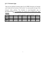
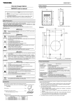
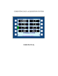
§ 2.1. Firmware type
There are few different firmware types for the MM32 because one firmware
can't include all the functions of the module. You must specify the type of the
firmware
while
ordering. The firmware
is
user-changeable
only in
Mini-Monster32NF. If not specified, the module will be shipped with Type1
firmware.
Type1
Type2
Type3
Type4
thermo watchdog PWM
RESET
JSON SNMP
TRAP
YES
YES
YES
YES
YES
NO
NO
YES
YES
NO
YES
NO
YES
NO
YES
NO
NO
NO
NO
YES
YES
NO
YES
NO
NO
NO
YES
YES
4
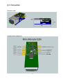
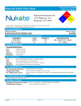
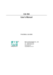
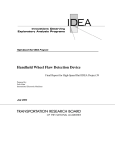
§ 3. Connection
General view
Inputs/outputs diagram
5
§ 3.1. Connection features
You can configure any of the universal IO ports as Input or Output (see
chapter 4). Be sure to configure all ports and save its state with "Save"
button before make any connections to it.
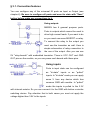
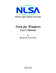
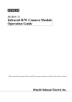
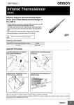
Using outputs
MM32N has 6 general purpose ports.
Ports in outputs which cannot be used to
drive high current loads. If you want to do
so you must use some MOSFET or relay.
To connect the relay to the output you
must use the transistor as well. Here is
simple schematics of relay connection to
the one of the output. Also you can use
5V "relay-boards" with embedded transistor. There is VCC OUT and GND
OUT pins on the module, so you can power such boards with those pins.
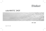
Using inputs
Ports in input state can be configured
as "tri-state" inputs or as "pulled"
inputs. In "tri-state" mode you can apply
some V from any device which has
common GND with module. In "pulled"
mode the inputs is pulled to the 3.3V
with internal resistor. So you can connect it to the GND with button or similar
switching device. Pay attention that in both cases you must not apply the
voltage higher than 3.5V to the inputs.
6
Pay attention that unconnected input in "tri-state" may become logical 0 or 1
randomly. So you can't use this type of connection without any pulling resistor
(internal or external).
PWM
PWM output have the same parameters with regular output. You can use
transistor to drive high load or connect it directly to PWM enabled devices
such as 4-pin PC coolers.
Temperature sensor connection
It's possible to connect 6 (six) digital temperature sensors to the module.
Maximum cable length is 50 meters. We don't recommend to use the wire
with diameter less than 0.5mm in case of long cable usage.
For a more accurate measurement of the temperature it is recommended to
connect the sensor with “pigtail” at least 10 cm length.
7
Power supply
MM32N requires DC 5-9V power supply. We recommend to use only new,
branded and/or tested power supply, and avoid used, no-name or unreliable
ones. Power supply's Vout must be stable and never will fall less than 5 V .
Maximum output current of the power supply depends of the summary
amperage requirements of all connected devices such as relays. It is very
recommended to avoid voltage fallings under 5 V especially because of
switching relays. Such power surges may cause unstable operation of the
module.
8
§ 4. Web-interface and controls
The Module has web-interface, and can be accessed via TCP/IP after
connecting to Ethernet and power supply.
Defaults are:
IP: 192.168.0.12
Password: password
MAC: F0-F1-09-E4-01-FF
So after first switching-on the Module can be accessed at address
http://192.168.0.12/password
9
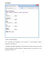
§ 4.1. Control sections
MAIN
Displays states of outputs/inputs and allows to switch outputs and input's
modes.
Color of port number shows port state at the moment (green - on, red - off.) if
port is output.
Inputs can be configured as pulled up (to positive) or tri-state (not pulled). To
switch states, use corresponding switch.
Capital letter (“H”igh or “L”ow) indicates input state at the moment.
10
“Set ports” section allows to configure ports direction (input or output). Also
here you can set port's name. Name must contain only alpha-numerical
characters and can be 10 characters long maximum.
«Save» button allows to save current states of outputs (on or off) as the
default state (after reset, for example, outputs will automatically be returned
to a saved state).
11
RESET
allows to do quick double inversion of output, example ON-OFF-ON.
Interval of this operation is general for all outputs; in seconds, max 255
seconds.
If «Thermostat» is activated for output, «T-mode» string will be shown instead
of reset switch; reset in thermostat mode is impossible.
If reset was done manually or by «watchdog» function, «resetting» will be
displayed instead of switch; reset will be disabled while resetting.
12
THERMO
provides thermostat functionality.
General information:
It's possible to connect up to 6 digital temperature sensors to “Mini-Monster”.
Maximum cable length is 50 meters. We don't recommend to use a wire with
diameter less than 0.5mm. You can enable «Thermostat» mode for each
output of the Module. So, Module will automatically turn ON and OFF that
output according to it's settings. Each sensor can be associated with multiple
outputs simultaneously with different settings for each output (thermostat).
All temperature values here are in Celsius.
Example: Output 1 is controlling main boiler in the house and Output 2 is
connected to emergency boiler. Sensor 1 is associated with both of them.
Output 1 has 23Co setting and Output 2 has 6 Co setting. So when main
boiler is working, temperature in the house is maintained on 23 Co . But in
case of main boiler failure when temperature falls below 6 Co, emergency
boiler will be started to avoid freezing.
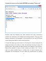
When the Thermostat page is open
for the first time you will see the
following page. The numerical row
on
the
right
represents
“Mini-
Monster's” ports . You must save
found sensors first. The «settings»
link below follows to «Sensors
search and save» page. Click it.
13
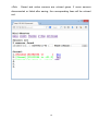
Connect all sensors to the module BEFORE proceeding "Sensor set"
Number under the «Sensors set» label indicates how many temperature
sensors are connected to the Module and working properly. There are all 6
sensors connected in this example. In the drop-list you can find all ID's and
actual temperature data for each connected sensor.
To save the sensor you must select it in the drop-list, choose saving slot by
typing its number to the «Save to» field, and optionally choosing it’s name (10
symbols max). After a while the saved sensor has to appear in the list below.
Repeat this operation to save all other sensors you want to use. You can
save one sensor multiple times to multiple slots, so saved sensors aren't
disappear from the drop-list. You can delete any saved sensor by clicking
14
«Del» . Saved and active sensors are colored green. If some sensors
disconnected or failed after saving, the corresponding lines will be colored
red.
15
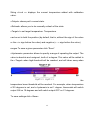
After sensors saving routine you can go back to the previews page by «Back»
in your browser or using «thermo» link above.
You can see, that the all saved sensors appeared in the list at the right. You
can see the name of each thermostat and current temperature readings. This
temperature is absolute and hasn't been affected by the calibration value.
By default all thermostats are turned OFF (red color). You can turn it ON by:
1. click on the number of the thermostat you want 2. click «turn ON» to
enable thermostat. Enabled thermostats are colored in green.
16
String «t+cal =» displays the current temperature added with calibration
value.
«Output» shows port's current state.
«Refresh» allows you to do manually refresh of the state.
«Target» to set target temperature. Temperature
can be set in both the positive (by default, that is, without the sign of the value
or the «+» sign before the value) and negative (« - » sign before the value)
ranges.To save a given parameter click “Save”.
«Hysteresis» parameter allows to specify a range of operating the output. The
value is absolute and unsigned, tenth of a degree. This value will be added to
the «Target» when high-threshold will be reached, and will taken away when
the
temperature lower threshold will be reached. For example, when temperature
of 20 degrees is set, and a hysteresis is set 1 degree, thermostat will switch
output ON on 19 degrees and will switch output OFF on 21 degrees.
To save settings click «Save».
17
The last parameter allows you to adjust the sensor, as different sensors often
has errors (usually linear) within two degrees. This value can be positive or
negative. This parameter is always added to or subtracted from the data
obtained from the sensor, and the «t+cal» string displays the corrected value.
Thermostat also works with temperature corrected by this parameter. If the
thermostat is turned ON, the first switch in the MAIN section will be replaced
with the inscription «thermo», and manual control of this output will be
disabled.
If one of the sensors fails during work of the Module, thermostats associated
with it will shutdown. If sensor isn't responding now there will be «XXXXX»
mark instead of temperature data.
«!» mark near the name of thermostat's output means that this thermostat
was turned OFF because of failure of the corresponding sensor.
It will not turn ON again automatically after if sensor goes back to normal.
Port can't work in «Thermostat» mode and in «Watchdog» mode
simultaneously, so when you turn ON the thermostat, the watchdog mode on
this port will be turned OFF (if it turned ON) and vice-versa.
18
W-DOG
provides automatic hardware reset for device wich power consuption is
controlled by “Mini-Monster” (by relay connected to the module) in case it is
not available in TCP/IP network.
Function provides monitoring and resetting 6 (six) hosts; each w-dog is
binded to port same number.
Navigation menu (numbers from 1 to 6 below main menu) provides access to
all Watchdogs.
Below navigation menu an informational frame is located. It contains:
19
info of function itself (is function ON or OFF) – 1st string;
amount resets done by function – 2nd string;
current output state – ON or OFF – 3rd string. If a name was set for output, it
will be used; otherwise number will be used.
If target host in unreachable, NR (not reachable) will be added in the 1st
string, for example: W-Dog 1 OFF (nr).
On main «W-dog» page you can set address of target machine and interval .
availability checking via TCP/IP through the ICMP (PING). You can set
checking frequency and additional parameters here.
The function is enabled, if «interval» is non-zero. In this case string of reset
statistics («W-dog stat = x») will be added to corresponding port .
«host» specifies ip-address of the host that will be monitored. The address
format is xxx.xxx.xxx.xxx, for example 192.168.10.5. If host is not reachable ,
«nr» will be displayed in «W-dog» main section, and uppercase «nr» symbol
will be displayed in «W-dog» navigation menu.
For monitoring hosts from non-local network, «gateway» option must be
used; see «Settings» for details.
If the function is enabled, after the reset section resets statistic will be
showed.
«Interval» parameter specifies the time interval in seconds after which the
availability check will be done. The range of values is from 1 sec. to 255 sec.
0 means deactivating the function.
To set another parameters, use «set» item.
20
«Reset interval» parameter specifies the time (in seconds) between switching
output off and on (power-on reset). Can be set from 1 second to 255 sec.,
recommended for at least 2 seconds.
«Lost before reset» parameter determines the number of packets lost (no
response for a request to the host)before the reset will be performed. For
example, if «Ping interval» = 2, and «lost before reset» = 4, then reset will be
done in 2 * 4 = 8 seconds if no response from the host was got in this eight
seconds. If at least one response is received, the no-response-counter will be
set to zero. The parameter can have a value from 1 to 255 seconds.
21
«Wait after reset» parameter determines the check delay after reset. For
example, if the computer is rebooted, it will be available in the network after
approximately 2-3 minutes. At this time, computer will be inaccessible from
network, and checking is useless. The parameter can have a value from 1 to
255 seconds.
«Failed resets» parameter determines how many times the equipment can be
resetted if the answers are not received after the restart. After the specified
number of restarts, if there will be still no response from the host, Watchdog
function will be disabled. The value can be from 1 to 255.
Important:
if more than 1 (one) host is monitored, we do not recommend using values of
parameters less than: interval – less than 3 (three) seconds; lost before reset
– less than 3 (three); wait after reset – less than 3 (three) seconds.
If not recommended values are used, web-interface may not function properly
and large delays in web-pages loading process are possible. It will not affect
proper functioning of watchdog function itself.
22
SNMP
From firmware version 2.5 “Mini-Monster” supports SNMP protocol v.1 (RFC
1155, RFC 1157).
This function can be enabled in “Settings”.
GET and GETNEXT request types are supported. The Module has all its data
in «Enterprise» space.
“Mini-Monster”'s Enterprise OID ̶ 43 (1.3.6.1.4.1.43)
Community string is the same as password to Module's web-interface.
Information that can be obtained from the Module by SNMP:
0. device_id – Module's name, oid 0, «String» format;
1-6. Module's output status, oid 1-6 (corresponds to output number),
«integer» format, syntax: 1 – ON, 0 – OFF;
7-12. Watchdog reset stat, oid 7-12 (corresponds to Watchdog function
number), «integer» format;
13-18. digital thermosensor temperature, oid 13-18 (corresponds to
thermosensor number), «singed integer» integer, must be divided by 10;
19. analog thermosensor temperature, oid 19, «signed integer», must be
divided by 10;
MIB's can be found at http://mini-monster.ru/index.php/en-US/dwnld-en.
23
SETTINGS
common module settings
«IP» specifies an IP address of the module in a local network. Default
address is 192.168.0.12.
«Gateway» specifies a gateway in local network to allow monitoring of hosts
that are located in another networks. Address format is xxx.xxx.xxx.xxx, for
example 192.168.10.1.
24
«MAC» specifies a unique module's physical MAC address . Change only if
necessary. Default – F0-F1-09-E4-01-FF.
«ID» specifies a name (just a label) of the module. Default is «Mini-Monster».
«Pass» is a password to the module. Default is «password».
FW ver string indicates current firmware version.
25
§ 5. Mini-Monster 32NF modification peculiar properties
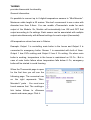
1. Firmware change and update
Can be done using special software (can be found at http://minimonster.ru/index.php/en-US/dwnld-en). To activate software change
mode click «change firmware» in «Settings».
2. Factory reset
Full software reset can be done if main firmware is not working properly
for some reason. To do so, connect «factory reset» pins for 5 (five)
seconds while turning Module ON. To simple reset settings on 32NF
modification, connect «factory reset» pins for 1 (one) second while
turning Module ON.
3. Limited functions set
For technical reasons, 32NF modification can have slightly less
software functions simultaneously than 32N.
All other parameters of 32NF modification are identical to 32N.
26
§ 6. Miscellaneous
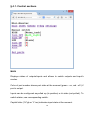
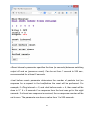
«Mini-Monster32N» can output its state in JSON format. Format of the JSON
query is: http://192.168.0.12/password/?js=
Answer is: {"fw":"MM32N v2.1 std b200714", "id":"Mini-Monster",
"prt":[0,0,0,0,0,0], "pst":[0,0,0,0,0,0],"t":[23.4,25.1,39.2,"No sensor","No
sensor","No sensor"],"wdr":[0,0,0,0,0,0]}, where:
- fwv – firmware version;
- id – module's name;
- prt – port state [array];
- pst – I/O: 1 – OUT, 0 – IN [array];
- t – temperature [array];
- wdr – watchdog resets [array].
Settings of the module are stored in non-volatile (EEPROM) memory, so after
the power settings they will be preserved. All the data is stored in EEPROM
of the Module except Watchdog function statistics.
To reset the module to the factory defaults, connect the pads when turning
the Module on (see Section 3).
We do not recommend to use the module at temperatures below +0 ° C and
above +40 ° C. The module was not long tested at these temperatures. If
exploitation for the temperature measurement in not-recommended temps is
needed, you may use an extension cord to connect the temperature sensor.
27