1
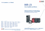
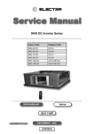
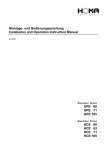
Documentation Author
Frederic Lambercy for K-Team S.A.
Rue Galilee 9
1400 Yverdon-les-Bains
Switzerland
email: [email protected]
Url: www.k-team.com
Trademark Acknowledgments:
IBM PC: International Business Machine Corp.
Macintosh: Apple Corp.
SUN Sparc-Station: SUN Microsystems Corp.
LabView: National Instruments Corp.
MatLab: MathWorks Corp.
Webots: Cyberbotics
Khepera: K-Team and LAMI
Legal Notice:
• The content of this manual is subject to change without notice.
• All effort have been made to ensure the accuracy of the content of
this manual. However, should any error be detected, please inform
K-Team S.A.
• The above notwithstanding K-Team can assume no responsibility for
any error in this manual.
K-Team S.A.
1
Table Of Contents
1 Introduction
4
2 KoreMotor Hardware
2.1 Overview . . . . . . . . . . . . . . . . . .
2.1.1 Dip Switch Settings . . . . . . . .
2.1.2 Controllers I2C Addresses . . . . .
2.1.3 Motor Connection Pinout . . . . .
2.2 KoreMotor Connections . . . . . . . . . .
2.2.1 Standalone Serial Connection . . .
2.2.2 KoreBot Connections . . . . . . .
2.2.3 Koala Connections . . . . . . . . .
2.2.4 Standalone I2C Connections . . . .
2.2.5 Motors Supply Connector . . . . .
2.3 Hardware Protection . . . . . . . . . . . .
2.3.1 Electrostatic Discharge Protection
2.3.2 Motor Controller Fuses . . . . . .
3 Motor Controler
3.1 Controler State or Mode . . . . . .
3.2 Controller Status Registers . . . .
3.2.1 Target Zone . . . . . . . . .
3.2.2 SoftStop Limits . . . . . . .
3.3 Controller Option Registers . . . .
3.4 Measurements . . . . . . . . . . . .
3.4.1 Position . . . . . . . . . . .
3.4.2 Speed . . . . . . . . . . . .
3.4.3 Current . . . . . . . . . . .
3.5 Regulation Type . . . . . . . . . .
3.6 Controller Speed Profile . . . . . .
3.7 SetPoint Sources . . . . . . . . . .
3.8 Motor Blocked Test . . . . . . . .
3.8.1 Mechanical Limit Detection
3.9 Sampling Period . . . . . . . . . .
.
.
.
.
.
.
.
.
.
.
.
.
.
.
.
.
.
.
.
.
.
.
.
.
.
.
.
.
.
.
.
.
.
.
.
.
.
.
.
.
.
.
.
.
.
.
.
.
.
.
.
.
.
.
.
.
.
.
.
.
.
.
.
.
.
.
.
.
.
.
.
.
.
.
.
.
.
.
.
.
.
.
.
.
.
.
.
.
.
.
.
.
.
.
.
.
.
.
.
.
.
.
.
.
.
.
.
.
.
.
.
.
.
.
.
.
.
.
.
.
.
.
.
.
.
.
.
.
.
.
.
.
.
.
.
.
.
.
.
.
.
.
.
.
.
.
.
.
.
.
.
.
.
.
.
.
.
.
.
.
.
.
.
.
.
.
.
.
.
.
.
.
.
.
.
.
.
.
.
.
.
.
.
.
.
.
.
.
.
.
.
.
.
.
.
.
.
.
.
.
.
.
.
.
.
.
.
.
.
.
.
.
.
.
.
.
.
.
.
.
.
.
.
.
.
.
.
.
.
.
.
.
.
.
.
.
.
.
.
.
.
.
.
.
.
.
.
.
.
.
.
.
.
.
.
.
.
.
.
.
.
.
.
.
.
.
.
.
.
.
.
.
.
.
.
.
.
.
.
.
.
.
.
.
.
.
.
.
.
.
.
.
.
.
.
.
.
.
.
.
.
.
.
.
.
.
.
.
.
.
.
.
.
.
.
.
.
.
.
.
.
.
.
.
.
.
.
.
.
.
.
.
.
.
.
.
.
.
.
.
.
.
.
.
.
.
.
.
.
.
.
.
.
5
5
6
7
7
8
8
8
10
10
10
11
11
11
.
.
.
.
.
.
.
.
.
.
.
.
.
.
.
12
12
13
14
14
14
15
15
16
16
16
17
18
19
19
20
4 Serial Communication Protocol
21
4.1 Generic User Syntax . . . . . . . . . . . . . . . . . . . . . . . 21
4.1.1 User Syntax Configuration Example . . . . . . . . . . 21
4.2 Regulation Type . . . . . . . . . . . . . . . . . . . . . . . . . 22
KoreMotor manual ver 2.0
2
A Register Summary
23
B Serial Commands Summary
26
K-Team S.A.
3
1 Introduction
The KoreMotor controler board can be used as a KoreBot extension or as
a standalone module that is able to control four DC motors. It provides an
open loop interface or PID algorithm control with several complementary
features such as current limitation, software position limits and internal
commands generator.
The KoreMotor can receive commands from a serial RS232 link, an I2C
bus or a KNet connection from a Koala or a KoreBot.
KoreMotor manual ver 2.0
4
2 KoreMotor Hardware
2.1
Overview
The KoreMotor hardware provides four motor controllers, each one including
a H-Bridge, microcontroler and motor connector. The fifth microcontroler
manage the board communications, dispatching orders to the controllers, it
is refered as the translator. Different settings and connections are required
depending on the KoreMotor usage. Dip switches control the board running
modes and the communication interface will set the required connections.
Figures 2.1 and 2.2 describe the board main components.
Motor 3
Motor 2
Serial Connector
1
8
3
2
1
Motors Supply
Connector
KNet Connector
Motor 1
Motor 0
Figure 2.1: KoreMotor hardware overview
KoreMotor manual ver 2.0
5
2.1.1
Dip Switch Settings
The running mode for the KoreMotor is set with the dip swicth position at
startup. The settings are described on figure 2.2. If the switch position is
modified at run time, the mode will not change until the next reset.
I2C Standalone : That mode is used to control the board from an I2C
bus. The I2C bus is directly connected to the motor controllers, and
the I2C addresses for each controller are detailled in section 2.1.2. The
translator is not used in this mode. The KoreMotor can be connecter
to any I2C master as a standalone I2C device, for instance a KoreBot
can be configured as an I2C master for the KoreMotor.
Koala KNet : The Koala KNet mode is the classical KNet protocol implemented on the Koala robot and the Khepera robot. This mode is
mainly designed to connect a KoreMotor as a Koala extension, refer
to the Koala user manual for details about the KNet protocol.
RS232 User Interface (115200): User serial commands (see section 4.1)
can be send to the KoreMotor serial interface with this mode. The
serial line settings should be 115200 bps, no parity, 8 data bits and 2
stop bits.
Dip switch settings
Reset switch
0: I2C standalone mode
1: standard SPI mode
2: KNet mode
3: RS232 115200bps mode
Figure 2.2: Dip switch settings
K-Team S.A.
6
2.1.2
Controllers I2C Addresses
I2C Adress range 1
I2C Adress range 2
Figure 2.3: KoreMotor I2C address range
The last dip switch, as displayed on figure 2.3 is used to choose the I2C
address range for the motor controllers. The address range is usefull to stack
two KoreMotor together, using the same I2C bus.
Motor
Motor
Motor
Motor
2.1.3
0
1
2
3
address
address
address
address
Range 1
0x01
0x02
0x03
0x04
Range 2
0x05
0x06
0x07
0x08
Motor Connection Pinout
7
5
3 1
10 8
6
4 2
9
1. Motor +
2. Encoder 5V
3. Encoder Canal A
4. Encoder Canal B
5. Encoder Gnd
6. Motor −
7. Motor +
8. Motor −
9. Encoder Index
10. Encoder Index
Figure 2.4: KoreMotor connector pinout
The KoreMotor provides four DC motor connectors. The motor connection may vary from a manufacturer to another, but the signals for quatrature encoders are usually similar. Please refer to your motors manufacturer datasheet for details about the motor connections, contact [email protected] if further help is necessary.
Motor+ : First motor connection
Motor- : Second motor connection
Encoder 5V : Power supply for the encoder
Encoder Gnd : Ground reference for the encoder
Encoder A : First encoder phase
K-Team S.A.
7
Encoder B : Second encoder phase
Encoder Index : Index for the encoder. This signal is not available for all
encoders and it is not required.
2.2
KoreMotor Connections
The KoreMotor requires a power supply connection and an external interface
connection. The main power supply is the motors supply, it should be
set according to the motors requirements, regarding voltage and necessary
current, and is common for all motors. Another supply may be necessary
for the electonics on the board. This supply is provided from the KoreBot
or the Koala when the KoreMotor is used as an extension, but it is required
for standalone use.
The external interface depends on the chosen dip switch settings. The
possibilities are:
- KoreBot connection for I2C or KNet 2.0 interface
- Koala connection for KNet interface
- Standalone serial connection for both RS232 interface
- Custom connection for a standalone I2C interface
2.2.1
Standalone Serial Connection
The standalone serial connection is used for both serial protocol mode. A
KoreConnect option, which provides the RS232 transceiver, is necessary
to use the KoreMotor in standalone serial mode. A custom made RS232
transceiver can be used as well, schematics are available on request at
[email protected]. The serial cable can then be connected to any PC.
A 5V supply voltage is required for the board electronic components (see
section 2.2.1).
How to Supply 5V for Electronics
When using the board as a standalone module, a 5V external supply is
necessary. That supply should be provided using the red KNet connector
(see section 2.1) as displayed on figure 2.6.
2.2.2
KoreBot Connections
The KoreBot connection is pretty straightforward, the boards should be
simply stacked together. The KoreBot will provide the electonics 5V supply,
and only the motors supply should be added.
Dip switch setting should be standalone I2C to use the I2C bus for
communications between the KoreBot and the KoreMotor.
K-Team S.A.
8
RS232 cables
KoreConnect
Figure 2.5: Standalone serial connection
1 GND
5V 8
Figure 2.6: Standalone 5V electronics supply
K-Team S.A.
9
2.2.3
Koala Connections
The Koala must be connected to the KoreMotor using the red KNet connector (see section 2.1). A cable should be provided with the KoreMotor
to be connected with the Koala K-Bus connector (please refer to the Koala
user manual for more details).
The electronics supply is provided from the Koala, the motors supply
can be connected to an external source or to the Koala 12V outputs.
Dip switches should be set to the Classical KNet mode, the Koala does
not support the KNet 2.0 protocol.
2.2.4
Standalone I2C Connections
1. I2C SDA 4. Serial Tx
2. I2C SCL
11. Gnd
3. Serial Rx 12. Gnd
9
7
5
3
1
12 10
8
6
4
2
11
Figure 2.7: KoreMotor serial connector and I2C connections
The KoreMotor can be connected to an external I2C bus, and controlled
as a set of standard I2C devices (see section 2.1.1 for details). Three signals (SDA, SCL and GND) are necessary to connect the I2C bus, they are
displayed on figure 2.7 with the relevant connections on the serial connector.
The electronics supply must be provided separately, and the dip switches
should be set to standalone I2C mode.
2.2.5
Motors Supply Connector
The main power connector will supply all the motors, the voltage should
match the motor requirements, and stay within the accepted voltage range
for the H-Bridges. The connector pinout is detailed on figure 2.8.
Voltage range
Max global current
Max current per motor
K-Team S.A.
5-28V
5A
2A
10
Ground
5−28V
1
8
3
2
1
Figure 2.8: Motors power connection
2.3
2.3.1
Hardware Protection
Electrostatic Discharge Protection
As any electronic device, the KoreMotor can be damaged by Electrostatic
Discharge. The quadature encoders interface chip on the board has been
identified as very sensitive and special care should be taken to avoid any
problem. It is recommended to connect the KoreMotor ground signal to the
earth or with the robot chassis for embedded use.
A quadrature encoder interface failure will shut the board ability to read
encoder feedback and globaly prevent the related motor controller proper
operation.
2.3.2
Motor Controller Fuses
The motor cotrollers are protected from overcurrent with dedicated fuses.
Each motor channel is protected with a 2 Amps fuse, and the board is
protected with a general 5 Amps fuse. Higher peak currents are normaly
supported by the board and all its components, but continuous operations
should respect these limits.
Please contact your K-Team dealer for support if a fuse replacement is
required.
K-Team S.A.
11
3 Motor Controler
3.1
Controler State or Mode
Each motor controller status is indicated, or can be modified, using the
mode register (0x28). This register should be read to check the controller
state, and it can be written to switch from a mode to another. The following
modes are available:
Idle mode: This is the default startup state (except if hardware option 0 is
set). While in idle mode the controller will not execute any regulation
and the motor is free wheeling.
Control mode: The controller must be switched to this mode for any regulation to start. When exiting Control Mode, the regulation will stop
according to the new mode description.
Stop mode: When switched to this mode, the controller will hold the motor in blocked state (both motor pins are electricaly connected).
Sleep mode: The controller is switched to a minimal activity status and
the motors are set to free wheeling. This mode can be used to optimize
power consumption.
Reset mode: Mode to reset the controller. The controller will then switch
to the startup mode, according to hardware option 0.
Save configuration mode: Save all registers to EEPROM for backup. A
special protection patern must be written in register 0x28 to access
this mode. Values 0x55, 0xAA and 0x05 must be written sequentially
to enter mode 5. The first two values are not stored to the register and
cannot be read. The controller will switch back to idle mode when the
backup is completed.
Search limit mode: This mode will start a mechanical limit detection
routine. The routine will use speed regulation to perform the test,
using the current target point setting and motor blocked test (see section 3.8). Resulting 32bit positions are stored in SoftStopMin (0x4A0x4D) and SoftStopMax (0x4E-0x51). The controller will switch back
to idle mode when the test is completed.
KoreMotor manual ver 2.0
12
3.2
Controller Status Registers
Two registers detail the motor controller status. Bit will be set by the controller in the Error register (0x2D) to signal problems. Generic information
about the controller are given in the Status register (0x2E).
Some errors, from error 0 to 4, are blocking errors, that means the controller will stop until the error are not cleared. The error will be cleared
only if the error condition has been resolved and after the Error register is
cleared from the application, that means writing 0x0 to the error register.
If a blocking error is triggered because of a physical condition, such as a
blocked motor, the condition itself should be resolved before clearing the
error register.
bit0 :
bit1 :
bit2 :
bit3 :
bit4 :
bit5 :
bit6 :
bit7 :
bit0 :
bit1 :
bit2 :
bit3 :
bit4 :
bit5 :
bit6 :
bit7 :
Error register
Sample time too small
The defined sample time is too small
for a complete calculation cycle.
Watchdog timer overflow Refer to the PIC16F876 datasheet
Brown-out
Refer to the PIC16F876 datasheet
Software stoped motor
The motor position is off-limits and
the sw stop error option is enabled.
Motor blocked
The motor blocked condition is
met (see section 3.8) and the
sw blocked stop option is enabled.
Position out of range
Not implemented
Speed out of range
Not implemented
Torque out of range
Not implemented
Status register
Movement detected
Motor speed is not null
Direction
Movement direction 0=negative
1=positive
On setpoint
The regulated value match the SetPoint value
Near setpoint
The regulated value is inside the target zone
Command saturated
The PWM ratio has reached 100%
Antireset windup active Set if the command is saturated and
if sw windup is enabled
Current control active
Softstop active
The position is off-limits and the
corresponding option is enabled
(section 3.2.2)
K-Team S.A.
13
3.2.1
Target Zone
The near setpoint flag is set whenever the regulated value is such as:
|SetP oint − RegulatedV alue| ≤ N earT argetM argin
That means the NearTargetMargin register defines a zone around the target
point. which can be useful for specific applications.
3.2.2
SoftStop Limits
The Controller can be configured to setup virtual position limits for movements. This feature is very useful to protect mechanical devices powered by
the KoreMotor. As soon as the position is under SoftStopMin (0x4A-0x4D)
or over SoftStopMax (0x4E-0x51), the controller will shutdown the motor
driver to prevent any further movement regardless of the target setpoint and
controller mode.
The SoftStopMax limit is only active if the sw stopmax option is enabled and the SoftStopMin limit is only active if the sw stopmin option is
enabled. Any combination of these two options is valid, and they should be
set according to each specific application requirements.
3.3
Controller Option Registers
The controller behaviour can be configured using the two option registers
(0x2A and 0x2B) where each bit will enable or disable a feature. The registers can be read at any time to retrieve the current option settings and
options are activated or disabled as soon as a register is written.
K-Team S.A.
14
Software option register
sw separated
Use alternate algorithm PID derivation.
The derivate part is calculated using the
process variable rather than the error.
Activate the anti reset windup routine.
sw windup
sw stopmin
Stop the motor if the min position is
reached (section 3.2.2).
Stop the motor if the max position is
sw stopmax
reached (section 3.2.2).
sw stop error
Generate an error when position is out of
limits, in this case the error must be reseted before any further commands can be
executed.
sw blocked stop Stop the motor if the blocked condition is
met (section 3.8).
sw current ctrl
Activate software current limitation (Not
implemented)
Invert the motor direction.
sw dir inv
bit0 :
bit1 :
bit2 :
bit3 :
bit4 :
bit5 :
bit6 :
bit7 :
bit0 :
hw
bit1 :
hw
bit2 :
bit3 :
hw
hw
bit4
bit5
bit6
bit7
hw
hw
hw
hw
3.4
:
:
:
:
Hardware option register
startup
Startup mode (0 = idle mode, 1 = control
mode)
analog set Use analog input for setpoint (Not Implemented)
led
Not Implemented
resolution Resolution for the encoder (0 = 100%, 1
= 25%)
torque inv Invert the internal current measurement
opt1
Not Implemented
opt2
Not Implemented
opt3
Not Implemented
Measurements
Each controller can return the motor incremental position, the motor current speed, and the current through the motor. Each measurement can be
retrieved reading the corresponding registers, the most significant bits for
each value should always be read first to ensure data consistency.
3.4.1
Position
The returned motor position is an accumulated counter of encoder pulses.
The physical position can be calculated knowing a reference position and the
K-Team S.A.
15
pulse per turn value for the encoder. The position registers can be writen
to set the current position to a given value at any time.
3.4.2
Speed
The speed value is a division of a constant value by the time between encoder
pulsations. In default mode (pulsation x2 and postcaler 1:4), a measure is
made every two pulsations. The constant value is define by the maximum
time multiplied by 256 (0xFFFF * 256 = 16’776’960). This operation allows
a better pid calculation for the lower speed.
16′ 776′ 960
T imer5value
To convert into a real time, use the following calculation:
M otorSpeed =
T ime =
T imer5value
fosc /4
T mr5P rescaler
Where fosc = 20MHz and Tmr5Prescaler = 8 (default).
3.4.3
Current
The measured current (Torque registers) is proportional with the maximum
supported current. The default maximum current is 2 Amps, and it is represented by a +512 measured current. A −512 value represents the reverse
maximum current (thus 2 Amps by default), any intermediate value can
be deduced from the proportional relation. The maximum supported current can be reduced to increase the current measurement resolution, please
contact K-Team for further information.
The current measurement can be disturbed because of the analog amplifier bias. That means a null value for the measured current does not
match the motor standby current. The Torque bias register (0x3C) is used
to correct this variation, the default bias is measured at startup, when it is
assumed the motor is not moving. The returned current value is corrected
using the bias such as:
RetunedV alue = M easuredV alue − Bias
The default bias can be modified if the startup value is incorrect.
3.5
Regulation Type
The controler supports six different type of regulation. Each regulation will
use a specific set of PID coefficient, depending on the parameter which is
actually regulated. The PID coefficients are usual proportional, derivate
K-Team S.A.
16
and integral gains for the controller, several other settings may be required
for each specific mode and application.
The 32 bit SetPoint value (0x2F-0x32) is always used as the controller
input. According to the regulation type, this register will set the target position, speed, or current. The actual controller internal input is only updated
when the least significant byte is written (0x2F) to ensure consistency.
Open Loop control: The open loop mode does not use the PID controller.
The SetPoint value will directly set the output PWM ratio. The PWM
timer for the controller is a 10 bit timer, that means the PWM ratio
can vary from +1024 to −1024 with the sign indicating the direction.
A null value generates no signal, while a 1024 value generate a 100%
PWM ratio (continuous signal).
Position control: The motor position is regulated to the SetPoint value.
The position coefficients are required for the PID controller.
Position control with speed profile: A speed profile is used to reach the
target position defined in the SetPoint registers. The speed regulation
is actually used to follow the speed profile that is why speed coefficients
are required for the PID controller. The position PID is not used in
this mode. The speed profile is defined by the MaxSpeed register
(0x6D) and Acceleration register (0x52), see section 3.6 for further
details. The final position is held using the blocked motor mode in the
target zone, which is defined using NearTargetMargin (0x60).
Speed control: The motor speed is regulated to the Setpoint value. As
speed is a 16 bit measurement, no speed beyond ±215 can be regulated.
The speed coefficients are required for the PID controller.
Speed control with acceleration profile: The motor speed is regulated
to the SetPoint value, but an acceleration ramp is used to reach the
final speed. According to the Acceleration register (0x52) and current
speed, the speed is gradually increased or deacreased until on SetPoint.
Current Control: The motor current is regulated to the SetPoint value.
As current is a 10 bit measurement, no current beyond ±29 can be
regulated. The current coefficients are required for the PID controller.
3.6
Controller Speed Profile
When using position control with speed profile mode, the controller aim
for a target position using a speed control PID. That means the position
itself is not regulated, even thought the given SetPoint is a position. On
the other hand, the motor speed is regulated according to the built-in speed
K-Team S.A.
17
profile. Figure 3.1 describe the speed profile, as it can be configured using
the MaxSpeed and Acceleration registers.
MaxSpeed
−Acceleration
Acceleration
Start Position
Target Position
Figure 3.1: Speed Profile
3.7
SetPoint Sources
The target point (see section 3.5) for the controller can be set from various
sources. The most common use is to set the target point by writting into the
SetPoint registers (0x2F-0x32) but other sources may be useful for specific
applications.
The source can be modified using the SetPoint Source register (0x29).
The default mode 0 requires writting to the SetPoint register, other modes
will use internal generators as described bellow.
Square Generator: As displayed on figure 3.2, the mode 2 will generate
a square wave signal for the SetPoint according to the IntGenPeriod,
IntGenAmplitude and IntGenOffset registers. IntGenOffset is a signed
value.
IntGenPeriod
(IntGenAmplitude/2) + IntGenOffset
0
−(IntGenAmplitude/2) + IntGenOffset
IntGenOffset
Figure 3.2: Square waveform
K-Team S.A.
18
Triangle Generator: As displayed on figure 3.3, the mode 3 will generate
a triangle signal for the SetPoint according to the IntGenPeriod, IntGenAmplitude and IntGenOffset registers. IntGenOffset is a signed
value.
(IntGenAmplitude/2) + IntGenOffset
0
IntGenPeriod
IntGenOffset
−(IntGenAmplitude/2) + IntGenOffset
Figure 3.3: Triangle waveform
3.8
Motor Blocked Test
The controller uses a built-in routine, based on movement and current measurement, to detect if the motor abnormaly blocked. A blocked condition is
met only if the motor is not moving and if the measured current is over the
defined SWCurrentLimit (0x56-0x57). The motor blocked flag and eventual
error are only triggered if the both conditions are met during at least a
BlockedTime (0x46) period.
That means the blocked flag will never be set if the motor is moving,
even very slowly, and it will never be set if the current limit is not defined
properly, according to the controlled system.
The blocked time period can be calculated from the sampling period
such as:
BlockedP eriod = 2 ∗ SamplingP eriod ∗ BlockedT ime
3.8.1
Mechanical Limit Detection
Controller mode 6 can be configured to use the built-in mechanical limit
detection routine. The mechanical limit detection is based on the motor
blocked test, that should be configured properly before switching to this
mode. The routine will use the current SetPoint value as the target speed
to perform the test, that is why the SetPoint register should be adjusted as
well.
K-Team S.A.
19
Once all relevant registers are set, switching to mode 6 will start the
detection routine. The routine will search for mechanical limits in both
directions. If no limit is reached in one direction or another, the test will
fail and the routine will run continuously, driving the motor at the given
SetPoint speed, until the controller mode is manually changed.
Resulting 32bits positions for mechanical limits are stored in SoftStopMin (0x4A-0x4D) and SoftStopMax (0x4E-0x51). The controller will switch
back to idle mode when the test is completed.
3.9
Sampling Period
The controller sampling period is the time between two output calculations.
That means the PWM ratio to control the motor is only updated once every
sampling period.
A shorter sampling period may result in a more accurate control but
requires a better encoder resolution. If the encoder resolution is too bad, the
controller might not count any pulse during a sampling period thus assuming
no movement, even if the motor is rotating. Moreover, if the sampling period
is too small, error 0 may occur, indicating that the microcontoller is too slow
to complete all the PID calculations in a single period.
On the other hand, if the sampling period is too long, the controller
might not be quick enough to regulate the system, as its reaction time might
become too long.
Setting a correct sampling period is critical to ensure proper motor control.
The Sampling period should be set using the SampleTimeH register
(0x45). The internal timer provide a 1.6µs resolution for the sampling time
so that the sampling period can be calculated as:
SamplingP eriod = (SampleT imeH ∗ 256) ∗ 1.6µs
The SampleTimeL register (0x44) can be used for finer tuning of the Sampling period, down to a 1.6µs resolution, but period under 1300µs are very
unlikely to be acceptable.
K-Team S.A.
20
4 Serial Communication Protocol
4.1
Generic User Syntax
The KoreMotor supports various high level serial commands to control the
board from a host Personnal Computer. The serial command syntax is
similar to the Khepera syntax with some enhancements.
Each command is a letter eventually followed by numerical arguments.
Arguments format is either 8bit (default), 8bit hexadecimal, or 32bit integer. The format for each argument is given in the command description (ie
value.format), but is 8bit by default. A prefix must be added to an argument
with a specific format as described in the following table:
32bit integer
l
16bit integer
d
8bit hexadecimal 0x
Some user command syntax examples:
Set options:
O,0,0x24,0x02
Set target point:
Set Position:
Configure PID:
4.1.1
P,0,1,l-100
A,1,l20
C,2,1,d300,d0,d120
User Syntax Configuration Example
Configuration of a motor controller (number mot) from the serial line.
W,mot,0x28,0
W,mot,0x33,0
W,mot,0x45,6
W,mot,0x60,10
W,mot,0x2D,0
W,mot,0x46,10
L,mot,5,l50,l0
L,mot,1,l-10000,l10000
O,mot,0,62
C,mot,3,d1500,d0,d300
C,mot,1,d70,d50,d10
J,mot,d10,1
S,mot
KoreMotor manual ver 2.0
-
Set mode
Set filter order
Set sample time
Set error margin
Reset all error flags
Set default blocked time
Set current limit
Set position limit
Set options
Configure speed PID
Configure position PID
Set speed profile
Save Config
21
N,mot,2,l3
R,mot,0x4A
R,mot,0x4B
R,mot,0x4C
R,mot,0x4D
R,mot,0x4E
R,mot,0x4F
R,mot,0x50
R,mot,0x51
4.2
- Search for limits
- Read min position byte
- Read min position byte
- Read min position byte
- Read min position byte
- Read max position byte
- Read max position byte
- Read max position byte
- Read max position byte
0
1
2
3
0
1
2
3
Regulation Type
The motor controller supports five different type of regulation (see section 3.5), serial commands set the affected regulation using a number, according to the following table. A command requiring a regulation type must
use one of these reference number.
0: Open loop control
1: Position PID control
2: Position control with a trapezoidal speed profile
3: Speed PID control
4: Speed with trapezoidal accelaration profile
K-Team S.A.
22
A Register Summary
Name
Mode
Address
0x28
SetPointSource
0x29
HW Options
0x2A
SW Options
0x2B
Description
Selection of mode (0..7)
0 = Idle Mode
1 = Normal Control Mode
2 = Stop Motor
3 = Sleep Mode
4 = Reset Mode
5 = Save configuration parameters (page 0) in E2PROM
6 = Search Limit Mode
7 = Unused
Source of SetPoint (0..7)
0 = External I2C
1 = External Analogic (not implemented)
2 = Internal Square Wave Generator
3 = Internal Triangle Generator
4 = Internal Sinus Generator (not implemented)
5 = Not used
6 = Not used
7 = Not used
Hardware options (Flags)
Bit0: Define Startup Mode,
0=Idle Mode / 1=Normal Control Mode
Bit1: Analog SetPoint Input, 0=disabled / 1=enabled
Bit2: LED, 0=disabled / 1=enabled
Bit3: Encoder resolution, 0=100% / 1=25%
Bit4: Torque Inversion
Bit5: Driver Option 1
Bit6: Driver Option 2
Bit7: Driver Option 3
Software options (Flags)
Bit0: Seperate D, 0=disabled / 1=enabled
Bit1: Antireset Windup, 0=disabled / 1=enabled
Bit2: SoftStop MIN, 0=disabled / 1=enabled
Bit3: SoftStop MAX, 0=disabled / 1=enabled
Bit4: Error on SoftStop, 0=disabled / 1=enabled
Bit5: Stop Motor when blocked, 0=disabled / 1=enabled
Bit6: Current Control by Software, 0=disabled / 1=enabled
Bit7: Direction invertion, 0=disabled / 1=enabled
KoreMotor manual ver 2.0
23
ControlTyp
0x2C
ErrorFlags
0x2D
StatusFlags
0x2E
SetPointLL
SetPointLH
SetPointHL
SetPointHH
PositionLL
PositionLH
PositionHL
PositionHH
SpeedLL
SpeedLH
SpeedHL
SpeedHH
TorqueL
TorqueH
TorqueBiasL
TorqueBiasH
0x2F
0x30
0x31
0x32
0x34
0x35
0x36
0x37
0x38
0x39
0x3A
0x3B
0x5A
0x5B
0x3C
0x3D
K-Team S.A.
Type of PID Control (0..7)
0 = Open Loop
1 = Position control with no speed Profile
2 = Position control with Trapezoal Speed Profile
3 = Speed control with no speed profile
4 = Speed control with Trapezoal acceleration Profile
5 = Torque control
6 = Zero Friction control (not implemented)
7 = Not implemented
Flags indicating an error (read only!)
Bit0: Sample time to small
Bit1: Watchdog timer overflow
Bit2: Brown-out
Bit3: SoftStop happened (only if SoftStop enabled)
Bit4: Motor blocked (only if Motor stop while blocked enabled)
Bit5: Position out of range (Overflow), 0=No / 1=Yes
Bit6: Speed out of range (Overflow), 0=No / 1=Yes
Bit7: Torque out of range (Overflow), 0=No / 1=Yes
Flags indicating the status of the controller (read only!)
Bit0: Movement detected, 0=No / 1=Yes
Bit1: Direction of movement, 0=negative / 1=positive
Bit2: On SetPoint, 0=No / 1=Yes
Bit3: Near SetPoint (+/-5units), 0=No / 1=Yes
Bit4: Saturation of Driver Command, 0=No / 1=Yes
Bit5: Antireset Windup active / Integrator Owerflow, 0=No / 1=Yes
Bit6: Current Control active, 0=No / 1=Yes
Bit7: SoftStop active, 0=No / 1=Yes
32bit target point
Target point is only updated when the LL value is writen
Always first read the PositionHH register!!!
These 4 variables contain a copy of the 32bit position
Always first read the SpeedHH register!!!
These 4 variables contain a copy of the 32bit Speed
Always first read the TorqueHH register!!!
These 2 variables contain a copy of the 16bit Torque
These 2 variables contain the 16bit Bias of the Torque Measurement
24
KpSpeedL
KpSpeedH
KdSpeedL
KdSpeedH
KiSpeedL
KiSpeedH
SampleTimeL
SampleTimeH
BlockedTime
0x3E
0x3F
0x40
0x41
0x42
0x43
0x44
0x45
0x46
IntGenPeriod
0x47
IntGenAmplitude
IntGenOffset
SoftStopMin
SoftStopMax
Acceleration
StaticFriction
SWCurrentLimitL
SWCurrentLimitH
MinSampleTimeL
MinSampleTimeH
TorqueL
TorqueH
MinSpeedL
MinSpeedH
NearTargetMargin
KpPos
KdPos
KiPos
KpTorque
KdTorque
KiTorque
MaxSpeed
0x48
0x49
0x4A
0x4E
0x52
0x54
0x56
0x57
0x58
0x59
0x5A
0x5B
0x5E
0x5F
0x60
0x61
0x63
0x65
0x67
0x69
0x6B
0x6D
Kp for speed PID
Kd for speed PID
Ki for speed PID
Sampling time [h=SamplingTime*1.6us] (20MHz)
Time to wait before the motor is considered blocked
[T=BlockedTime*256*h]
Period of internal function generator
[T=IntGenPeriod*256*h] (0..255)
Amplitude of internal function generator (0..255)
Offset of internal function generator (-127..127)
32bit Position of SoftStop minimum
32bit Position of SoftStop maximum
Acceleration for trapezoidal speed profile (0..255)
Friction of the system (0..255)
Software current limit (16 bit)
used for blocked detection and software current limit
Time used to pass one cycle
Always first read the TorqueHH register!!!
These 2 variables contain a copy of the 16bit Torque
Minimal consigne Speed for regulation control with trapezoidal or constant speed
Margin for near target flag setting and speed profile
Kp for Position PID
Kd for Position PID
Ki for Position PID
Kp for Current PID
Kd for Current PID
Ki for Current PID
Maximum speed for trapezoidal speed profile
K-Team S.A.
25
B Serial Commands Summary
A
Set Position
Command:
Answer:
Effect:
B
Read Software Version
Command:
Answer:
Effect:
C
A, mot, position.32
a
Set the position counter for the given controller.
B
b, TranslatorVersion, ControllerVersion
Give the software version for the translator firmware and the
motor controller firmware.
Configure PID controller
Command:
Answer:
Effect:
C, mot, RegulationType, Kp.16, Kd.16, Ki.16
c
Configure the PID controller for the given regulation, set the
proportional (Kp), integral (Ki), and derivative (Kd) gain.
These parameters must be set separately for each regulation
type.
D
Unused
E
Get controller status
Command:
Answer:
Effect:
E, mot
e, 0xStatusFlags, 0xErrorFlags
Return the status and error flags for the given controller.
Refer to section 3.2 for flags definition. Both returned values
are 8bit integer.
F
Unused
G
Unused
KoreMotor manual ver 2.0
26
H
Set Source for the Regulation Target Point
Command:
Answer:
Effect:
H, mot, RegulationType, Source, Period, Amplitude, Offset
h
Set a new target point source for the given controller. The
default source is to use external commands from the translator. This command will start regulation according to the
new source, other relevant parameters should be set fisrt.
I
Unused
J
Set Speed Profile
Command:
Answer:
Effect:
J, mot, MaxSpeed.16, Acceleration
j
Set the speed profile for regulation type 2, which is position
control using a trapezoidal speed profile.
K
Unused
L
Set System Limits
Command:
Answer:
Effect:
M
L, mot, RegulationType, ValueMin.32, ValueMax.32
l
Set software limits for position, speed or current. The affected limit is determined from the given regulation type. 1
or 2 affect position, 3 or 4 affect speed, and 5 affects current. Warning: to set the current limit, only the 16 least
significant bits of the ValueMin are used. These 16 bits are
interpreted as an unsigned integer.
Get Measurement
Command:
Answer:
Effect:
K-Team S.A.
M, mot, RegulationType
m, Measure
Get speed, position or current measurement from the given
motor. The returned value is a 32bit integer and the measurement is determined from the given regulation type. 1 or
2 give position, 3 or 4 give speed, and 5 give current.
27
N
Search System Mechanical Limits
Command:
Answer:
Effect:
O
Set Controller Options
Command:
Answer:
Effect:
P
N, mot, BlockedTime, Speed.32
n,
Use the given speed, to initiate limits detection cycle. The
limit detection is based on the current limit set with L, and
the given time. Refer to section 3.8 for a detailled description of the detection cycle.
O, mot, HardwareOption, SofwareOption
o
Set options for the given controller, refer to section 3.3 for
a detailled description of available options.
Set New Target Point
Command:
Answer:
Effect:
P, mot, RegulationType, TargetPoint.32
p
Start the regulation to the new target point. The regulation
type determine if the setpoint is a speed, position or current
target. All other parameters relevant for regulation should
be set first.
Q
Unused
R
Read I2C Register
Command:
Answer:
Effect:
S
R, mot, Address
r, 0xData
Read a register from the given controller. The returned value
is the 8bit content of the register, and the Address should be
a valid 8 bit address either decimal or hexadecimal. Refer
to section A for register descriptions.
Save Controller Configuration
Command:
Answer:
Effect:
K-Team S.A.
S, mot
s
Store all registers value to EEPROM for the given controller.
These saved values are not erased when the card is switched
off and are automatically restored at startup.
28
T
Unused
U
Unused
V
Unused
W
Write to I2C Register
Command:
Answer:
Effect:
W, mot, Address, Data
w
Write a value to the given register. The address should be
a valid 8bit decimal or hexadecimal address and the value a
8 bit integer.
X
Unused
Y
Unused
Z
Unused
K-Team S.A.
29