1
Radiocrafts
Embedded Wireless Solutions
MBUS
MBUS User Manual
2010 Radiocrafts AS
MBUS User Manual (rev. 1.40)
Page 1 of 43
Radiocrafts
Embedded Wireless Solutions
MBUS
Table of contents
TABLE OF CONTENTS ............................................................................................................ 2
QUICK START .......................................................................................................................... 3
MBUS FEATURE SETS ............................................................................................................ 4
OPTIONAL CUSTOM SPECIFIC VERSION ............................................................................ 4
IMPORTANT NOTE ON PATENT PENDING TECHNOLOGY ................................................ 5
INTRODUCTION: NETWORK TOPOLOGY ............................................................................. 5
WIRELESS M-BUS EMBEDDED PROTOCOL ........................................................................ 6
BASIC FUNCTIONALITY .............................................................................................................. 6
UART INTERFACE FOR W IRELESS M-BUS PACKET HANDLING ..................................................... 7
FRAME FORMAT FOR TRANSMITTING DATA .................................................................................. 8
FRAME FORMAT FOR RECEIVING DATA ....................................................................................... 8
UART INTERFACE FOR MODULE CONFIGURATION...................................................................... 9
UART TIMING INFORMATION ................................................................................................... 10
POWER MANAGEMENT ............................................................................................................ 12
RSSI READING ...................................................................................................................... 12
MBUS1 DESCRIPTION .......................................................................................................... 13
MBUS1 TIMING TABLE ........................................................................................................... 13
MBUS1 CONFIGURATION COMMANDS..................................................................................... 14
MBUS1 CONFIGURATION MEMORY ......................................................................................... 16
MBUS2 DESCRIPTION .......................................................................................................... 18
MBUS2 AUTOMATIC ACKNOWLEDGE ...................................................................................... 18
MBUS2 AUTOMATIC ADDRESSING .......................................................................................... 18
MBUS2 AUTOMATIC SLEEP .................................................................................................... 18
MBUS2 INSTALLATION AND BINDING ....................................................................................... 19
MBUS2 ENCRYPTION............................................................................................................. 19
MBUS2 TIMING TABLE ........................................................................................................... 22
MBUS2 CONFIGURATION COMMANDS..................................................................................... 23
MBUS2 CONFIGURATION MEMORY ......................................................................................... 25
MBUS3 DESCRIPTION .......................................................................................................... 28
MBUS3 AUTO-MESSAGE GENERATOR .................................................................................... 28
MBUS3 AUTOMATIC ADDRESSING .......................................................................................... 30
MBUS3 AUTOMATIC SLEEP .................................................................................................... 30
MBUS3 INSTALLATION AND BINDING ....................................................................................... 31
MBUS3 ENCRYPTION............................................................................................................. 31
MBUS3 REPEATER ................................................................................................................ 32
MBUS3 TIMING TABLE ........................................................................................................... 33
MBUS3 CONFIGURATION COMMANDS..................................................................................... 34
APPENDIX: MBUS COMMAND LIST OVERVIEW ................................................................ 39
APPENDIX: CONFIGURATION MEMORY FACTORY DEFAULT ........................................ 40
APPENDIX: ASCII TABLE ..................................................................................................... 42
DOCUMENT REVISION HISTORY......................................................................................... 43
DISCLAIMER .......................................................................................................................... 43
TRADEMARKS ....................................................................................................................... 43
LIFE SUPPORT POLICY ........................................................................................................ 43
CONTACT INFORMATION ..................................................................................................... 43
2010 Radiocrafts AS
MBUS User Manual (rev. 1.40)
Page 2 of 43
Radiocrafts
Embedded Wireless Solutions
MBUS
Quick Start
How do I transmit data?
Send your data to the RXD pin on the module. Use the UART format with settings (19200, 8,
1, N, no flow control). Up to 128 bytes are buffered in the module. The first byte of the
message must contain the message length. The module will transmit the data when the whole
packet is received.
How do I receive data?
Any received RF data packet with correct Wireless M-Bus format and check sums will be sent
on the TXD pin. Optionally the meter address (first M-Bus block) is added to the data string.
The RSSI value (received signal strength) can optionally be added to the message.
What about the antenna?
In most cases a simple quarter wavelength wire or a PCB track will do. Connect a piece of
wire to the RF pin with length corresponding to the quarter of a wavelength. For space limited
products, contact Radiocrafts and we will recommend the best antenna solution for your
application.
How do I change the M-Bus mode, RF channel or any other parameter?
To change configurable parameters, send one byte to the module with the value 0x00 or
assert the CONFIG-pin. This will take the module into configuration mode. Special commands
are then used to access the configuration registers and test modes. Exit from configuration
mode by sending the ‘X’ command. Parameters can be changed permanently and stored in
non-volatile memory in the module.
2010 Radiocrafts AS
MBUS User Manual (rev. 1.40)
Page 3 of 43
Radiocrafts
MBUS
Embedded Wireless Solutions
MBUS feature sets
This User Manual describes the embedded protocol of the Wireless MBUS Modules from
Radiocrafts. The MBUS firmware is available as different feature sets targeting specific
applications. The hardware has the same size and pin-out for all frequency versions, and the
different feature sets available are listed in the table below. The feature sets and the
embedded functions are independent of the frequency, so this user manual is valid for all
versions RC11xx-MBUSx. Detailed information on how to use the different feature sets is
found in this User Manual. Additional information about the Wireless M-Bus packet structure
for NTA 8130 compliance is described in Application Note 011 and is available on request.
Feature List
General
MBUS1
Basic wireless M-bus
functions
Network role
Master or Slave
Feature set
MBUS2
Added features for
DSMR/NTA 8130
compliance
Master or Slave
Modes
Encryption
S1, S2, T1, T2, R2
No, must be handled
externally
No, Must be handled
externally
None
T1, T2
AES according to NTA
8130 (mode 4 and 5)
Yes, according to NTA
8130
Up to 8
Installation
mode
Number of
installed
meters
Filter function
No, receives any
MBUS packet.
Filtering must be
handled externally
Automatic
No, must be handled
acknowledge in externally
T2
Automatic
No
message
acknowledge
from Master
MBUS3
Added features for OMS
compliance
Master, Slave or
Repeater
S1, S2, T1, T2
AES according to OMS
(mode 4 and 5)
Yes, according to OMS
Up to 64
Master only receives
messages from
installed/registered
meters (optional)
Yes, according to
NTA8130
Master only receives
messages from
installed/registered
meters (optional)
Yes, according to OMS
No
Yes, according to OMS,
supporting two-way
slaves; Standard
acknowledge or a
predefined message from
mailboxes or templates
The command set used to configure the MBUS modules are different for each feature set and
an overview is found in the appendixes.
Note that this user manual also is applicable for the RCxxxxTX-MBUS. This is a TX only
hardware and the RX features described in this user manual is not supported.
Optional custom specific version
As an option to the standard feature sets, a full wireless M-Bus application layer can be
integrated in the module based on customer specification. In this case all the application layer
protocol and timing will be handled internally by the module. See Data sheet for details.
2010 Radiocrafts AS
MBUS User Manual (rev. 1.40)
Page 4 of 43
Radiocrafts
Embedded Wireless Solutions
MBUS
Important note on patent pending technology
Some of the technical solutions described in this User Manual are based on patent pending
technology. In particular the methods used in the MBUS3 to meet the T2 timing requirements
for a master, using an address register, a flag register, an encryption key register combined
with an auto-message generator for standard messages and its combination with a mailbox
with pre-generated messages or templates, and a given message priority, depending on
incoming messages, are subject to patenting.
Any infringements of patents and IP rights held by Radiocrafts will be prosecuted to the fullest
extent.
Introduction: Network Topology
A Wireless M-Bus supported metering system normally consists of a number of heat-, gas-,
water and/or electricity meters which reports their meteorological readings to a concentrator.
The concentrator acts as the master in the system while the meters are slaves.
The Radiocrafts Wireless M-Bus family of modules RC11xx-MBUSx can be configured to
have a role as either master or slave. The slave contains a unique address, and when
sending a meter reading this address is added to the wireless message. The message from a
slave does not contain any master address but the master module within range will receive
the message, and based on the slave address (if the slave is installed and master configured
for filtering), it will decode the message and send the data on its serial interface (TXD-pin).
In two-way communication modes, the battery operated meter (slave) will keep the receiver
“on” for a short time. During this time slot the master can acknowledge the received message
in order to open the communication channel (NTA 8130), or send a command (OMS) and
thereby start a communication sequence. Note there is a difference in the addressing scheme
between NTA 8130 and OMS: In NTA 8130 (MBUS2) the master returns an addressed
acknowledgement to the slave using the address field (Link Layer Address) originally received
from the slave. In OMS (MBUS3) the master sends a command with it’s own address as Link
Layer Address, and the slave’s address as Application Layer Address.
MBUS3 (OMS) also allows for a one-way (unidirectional) repeater. The repeater will retransmit all messages from slaves within range. Modules with MBUS3 features set can be
configured as a repeater.
2010 Radiocrafts AS
MBUS User Manual (rev. 1.40)
Page 5 of 43
Radiocrafts
Embedded Wireless Solutions
MBUS
Wireless M-Bus Embedded Protocol
Basic functionality
The module offers a buffered packet radio acting as a Wireless M-Bus modem. The module
contains a fully embedded protocol supporting EN13757-4:2005 modes:
• Stationary mode S (S1, S1-m, S2)
• Frequent transmit mode T (T1 and T2)
• Frequent receive mode R2
The mode is configurable by the MBUS_MODE parameter.
The required M-Bus mode is configured by setting the module in configuration mode and
entering appropriate UART commands. The following modes are supported:
S1/S2-mode:
Set MBUS_MODE = 0
Set PREAMBLE_LENGTH = 0 (for short preamble) or 1 (for long preamble)
The RF channel (channel 11) and data rate (32.768 kchip/s) are set internally in the module
according to the S mode, and will override any settings in the RF_CHANNEL and
RF_DATA_RATE configuration registers. This setting can also be used for T2 mode slave
receive and master transmit.
T1-mode:
Set MBUS_MODE = 1
The RF channel (channel 12), data rate (100 kchip/s) and preamble length are set internally in
the module according to the T mode, and will override any settings in the RF_CHANNEL,
RF_DATARATE and PREAMBLE_LENGTH configuration registers. This setting can also be
used for T2 mode slave transmit and master receive.
T2-mode:
Set MBUS_MODE = 2
Set NETWORK_ROLE = 0 or 1
The RF channel (channel 11 or 12), data rate (32.768 or 100 kchip/s) and preamble length
are set internally in the module according to the T2 mode and the selected Network Role,
either being a Slave (NETWORK_ROLE = 0) or a Master (NETWORK_ROLE = 1), and
change according to receive/transmit. It will override any setting in the RF_CHANNEL
configuration register.
R2-mode:
Set RF_CHANNEL = 1-10
Set MBUS_MODE = 4
The data rate (4.8 kchip/s) and preamble length are set internally in the module according to
the R mode.
The module supports automatic generation of the Wireless M-Bus frame, i.e.;
- Preamble (header + synchronisation)
- Adding the first block (C-field and address/manufacturing ID)
- CRC
- Postamble
The RF signal is Manchester coded or "3 out of 6" coded for increased signal integrity.
The default M-Bus mode is entered and stored in the modules’ non-volatile memory
(MBUS_MODE). The M-Bus mode can also be changed using the ‘G’ command. Using the
‘G’ command, the value is not stored in non-volatile memory. To do a permanent change, use
the ‘M’ command. The ‘G’ command should be used for frequent change of mode, to prevent
excessive writing to the flash-based non-volatile memory.
2010 Radiocrafts AS
MBUS User Manual (rev. 1.40)
Page 6 of 43
Radiocrafts
Embedded Wireless Solutions
MBUS
The default C-field is entered and stored in the modules’ non-volatile memory
(CONTROL_FIELD). The C-field can also be changed using the ‘F’ command. Using the ‘F’
command, the value is not stored in non-volatile memory. To do permanent change, use the
‘M’ command.
The default Manufacturer ID and unique meter Address is entered and stored in the modules’
non-volatile memory. The destination address (or module address) can also be changed
using the ‘T’ command. Using the ‘T’ command, the address is not stored in non-volatile
memory. To do a permanent change, use the ‘M’ command. MBUS2 sets the destination
address automatically based on the last received message.
The module has an internal buffer and transmits application data as soon as the whole packet
is received based on the packet length (first byte of the application frame). The module also
has a timeout feature that will empty the input buffer in case of false data packets. The default
timeout is 2 seconds.Max total payload is 246 bytes, or 255 including the header in the first
block.
Sleep mode can be entered via an UART command and wake-up is triggered on UART traffic
(one FFh byte). Sleep mode can also be entered automatically after a transmission
(configurable by SLEEP_MODE).
The module acts as a buffered packet radio, hence all data to be sent is stored in the module
before they are transmitted by the RF circuitry. Likewise, when data is received they are
stored in the module before they are sent to the host. This allows the communication
controller to add address information, CRC and encryption during transmission, and to do
error check and decryption of the received data.
The Module has an UART interface that is used for both Wireless M-Bus packet data and
module configuration.
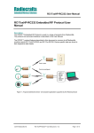
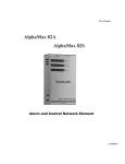
UART Interface for Wireless M-Bus packet handling
The host use the UART Interface to send and receive Wireless MBUS data. The UART
packet format can be changed in the configuration mode.
When the Module receives a Wireless M-Bus packet over RF it will send the packet over the
UART interface on the TXD Line. When the host MCU wants to transmit a Wireless M-Bus
packet over the RF, it must send the packet through the UART Interface on the RXD line.
Figure 1: UART interface overview
2010 Radiocrafts AS
MBUS User Manual (rev. 1.40)
Page 7 of 43
Radiocrafts
Embedded Wireless Solutions
MBUS
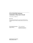
Frame format for transmitting data
The data frame for the UART RXD pin (input for transmitting a Wireless M-Bus packet) is built
like this:
Figure 2: UART interface packet transmission (RXD pin)
L is the length (not including the length byte itself), followed by the application data with the CI
byte first. CI is the Control Information byte. The application data typically contains the
application header, and data points with VIF and DIF codes. The application data can also be
SML of DMLS.
The HEADER and C-field (and adjusted L value) is added to Wireless M-Bus packet
automatically by the module before transmitting over RF and both can be changed in
configuration mode.
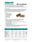
Frame format for receiving data
The data frame for the UART TDX pin (Output for received Wireless M-Bus packets) is built
like this:
Figure 3: UART interface packet reception (TXD pin)
Data in blue and yellow are optional output parts of the UART message and can be enabled
in configuration mode by the DATA_INTERFACE and RSSI_MODE configuration parameters.
L is the length byte and is always present. It does not include itself or the START/STOP
bytes, but will include RSSI and CRC if enabled.
When setting DATA_INTERFACE = 1, the received HEADER will not be sent on the UART
(typically used on a slave). However, to be able to notify the external application when an
Acknowledgement is received (“empty” frame), a special string can be used. By setting
DATA_INTERFACE = 3, the two byte string 00:E5h (i.e. L = 0) will be sent on the UART when
an empty acknowledge frame is received.
Application data (CI + APPL_DATA) is always present (except when only a HEADER is
transmitted).
For host applications using a UART buffer the timing information used for parsing could be
lost. In this case a start and stop byte can be used. Setting DATA_INTERFACE = 4 will add a
2010 Radiocrafts AS
MBUS User Manual (rev. 1.40)
Page 8 of 43
Radiocrafts
Embedded Wireless Solutions
MBUS
START byte (68h) and a STOP byte (16h) to the message. This is only used for the moduleto-host communication direction (TXD). Setting DATA_INTERFACE = 8 will add a two byte
CRC checksum, and DATA_INTERFACE = 0Ch will add START/STOP bytes and CRC. The
CRC is sent MSByte first.
The RSSI value is added when RSSI_MODE = 1.
UART Interface for Module Configuration
The configuration of the module can be changed in-circuit from the host during operation, at
the time of installation of the equipment, at the manufacturing test, or even as a stand-alone
module. The configuration is changed by sending commands on the UART interface after the
module is set in configuration mode. The configuration mode is entered by sending 00h to the
module, or by asserting the CONFIG pin (set low).
In configuration mode the module will respond by sending a ‘>’ prompt on the TXD pin. This
indicates that the module is ready to receive commands. The CONFIG pin (if used) can then
be de-asserted. Note that the CONFIG pin must be de-asserted before the Exit command
(‘X’) is sent to the module in order to return to normal operation.
After a command is executed, the module responds with the ‘>’ prompt character again,
indicating it is ready for a new command. Do not send a new command before the ‘>’ prompt
is received. The time required to execute a command can vary depending on the command
(see the Timing Information section). There is no ‘>’ prompt after the ‘X’ exit command.
The parameters that are set by dedicated configuration commands (‘C’, ‘P’ etc) take
immediate effect after returning to normal operation (IDLE), but will not be stored in nonvolatile memory and will be lost in case the supply power is turned off or if the module is
reset. These parameters are for example the radio channel and output power.
Permanent changes of parameters can be done by writing to the configuration memory using
the memory command ‘M’. These are for example default radio channel, default output power
and M-Bus mode, see the Configuration Memory section for details.
The flow diagram bellow illustrates how to use the UART interface to enter configuration
mode, change configuration parameters and return to IDLE mode.
Figure 4: Configuration mode flow diagram
2010 Radiocrafts AS
MBUS User Manual (rev. 1.40)
Page 9 of 43
Radiocrafts
Embedded Wireless Solutions
MBUS
UART Timing Information
A UART byte consist of one start bit, 8 data bits, and one stop bit. In configuration mode a
command to prompt reply will looks like this:
Figure 5: UART Command and prompt
The command-to-prompt wait time (T_Command2Prompt_WAIT) is different from command
to command and values are shown in the timing table for each MBUS feature set.
The IDLE state is the normal state where the module both searches for preamble on the RF
and wait for a character to be received on the UART. RXD is the state when receiving
characters from the host filling up the internal buffer. TX state is when the data is transmitted
on the air. RX state is when data is received from the air after preamble detection. TXD is the
state where the received data is sent to the host on the UART.
CONFIG is the configuration mode, the state entered by sending 00h or asserting the
CONFIG pin and is entered during parameter configuration, while MEMORY CONFIG is the
sub-state entered by the ‘M’ command where the non-volatile configuration memory is being
programmed. Note the limitation on maximum number of write cycles using the ‘M’ command,
see Electrical Specifications.
2010 Radiocrafts AS
MBUS User Manual (rev. 1.40)
Page 10 of 43
Radiocrafts
MBUS
Embedded Wireless Solutions
tTXD
tRX-TXD
RX
IDLE
tTXD-IDLE
TXD
Preamble detected
First character on
UART TXD
IDLE
Last character on
UART TXD
tRXD-CTS
RXD
IDLE
First character on
UART RXD
tPACKET_TIMEOUT
tTX
tTX-IDLE
tRXD-TX
TX
IDLE
Last character on
UART RXD
tOFF-IDLE
OFF
IDLE
tRESET-IDLE
RESET
IDLE
tSLEEP-IDLE
SLEEP
IDLE
tCONFIG-PROMPT
IDLE
tC-CONFIG
CONFIG
MEMORY CONFIG
’M’
IDLE
’X’
’C’
CONFIG
set low
CONFIG
tCONFIG-IDLE
CONFIG
tCONFIG-IDLE
tMEMORY-CONFIG
CONFIG
0xFF
IDLE
’X’
Figure 6: UART timing diagram
Timing values are shown in the timing table for each MBUS feature set.
2010 Radiocrafts AS
MBUS User Manual (rev. 1.40)
Page 11 of 43
Radiocrafts
Embedded Wireless Solutions
MBUS
Power Management
The module can be set in SLEEP mode in order to reduce the power consumption.
The low power SLEEP mode is manually entered by using the SLEEP command ‘Z’ after the
module is set in configuration mode. It is also possible to configure the module to enter
SLEEP automatically after a message has been transmitted (SLEEP_MODE=1). With this
setup the module has to enter TX-mode (transmit a message) after power-on before entering
SLEEP mode first time. In SLEEP mode the module will not receive or detect incoming data,
neither from the host (UART port) nor from the air. The module is awakened from the SLEEP
mode by sending the wake-up byte FFh on the UART RXD line (use a UART Baud rate > 4.8
kBd due to a maximum pulse length requirement). After the module has woken up (see
Timing Information) it is ready to receive data on the UART or from the air. The SLEEP
command can be used for both Master and Slave.
All configuration settings and RAM values are retained during SLEEP.
If the module is shut completely off (supply power turned off), all configuration settings in nonvolatile memory is restored, but values in RAM are overwritten with default settings.
RSSI Reading
The module provide a digital Received Signal Strength Indicator (RSSI) through the ‘S’
command, or attached to the received messages. The RSSI value appended to a received
message is the signal strength of that received packet. The RSSI value is an 8 bit character
(one byte) indicating the current input signal strength or the signal strength of the received
message. The signal strength can be used as an indication of fading margin, or as a carrier
sense signal to avoid collisions.
The RSSI value increases with increased input signal strength in 0.5 dB steps. Input signal
strength is given by (typ.):
P = - RSSI / 2 [dBm]
2010 Radiocrafts AS
MBUS User Manual (rev. 1.40)
Page 12 of 43
Radiocrafts
MBUS
Embedded Wireless Solutions
MBUS1 Description
MBUS1 Timing table
The table below shows the timing information for the module when changing between
different operating states. Timing symbols are according to figure 5 and 6.
Symbol
tRX-TXD
Value
180 us
tTXD
Min 590 us
tTXD-IDLE
900 us
TRXD-CTS
20 us
tRXD-TX
960 us
TTX-IDLE
960 us
tOFF-IDLE
tRESET-IDLE
tSLEEP-IDLE
tCONFIG-PROMPT
TC-CONFIG
3.2 ms
3.0 ms
1.3 ms
60 us
1.1 ms
TG-CONFIG
1.1 ms
TWAIT
tMEMORY-CONFIG
1.55 ms (M
command)
24 us (all other
commands)
31 ms
TCONFIG-IDLE
tTX
1.1 ms
3.6 ms
2010 Radiocrafts AS
Description / Note
Time from last byte is received from the air until first
character is sent on the UART
tTXD = # bytes received x 590 us/char (10 bits at 19.2 kBd +
70 us delay per character)
Time from last character is sent on the UART until module
is in IDLE mode (ready for RXD and RX)
Time from last character is received by the UART
(including any timeout) until CTS is activated
Time from last character is received by the UART
(including any timeout) until the module sends the first
byte on the air.
Time from last character is sent on the air until module is
in IDLE mode (ready for RXD and RX)
Time from 00h / CONFIG pin is set low until prompt (‘>’)
Delay after channel-byte is sent until prompt (“>”).(For other
volatile memory commands there is no delay but
immediate prompt)
Delay after new M-Bus mode-byte is sent until prompt
(‘>’). (For other volatile memory commands there is no
delay but immediate prompt)
Delay from stop bit of the command byte to start bit of the
prompt reply. See figure 5 for details.
In this period the internal flash (non-volatile memory) is
programmed. Do not reset, turn the module off, or allow
any power supply dips in this period as it may cause
permanent error in the Flash configuration memory. After
the last command parameter byte the host should wait for
the ‘>’ prompt before any further action is done to ensure
correct re-configuration.
End of ‘X’ to IDLE
TX time for T1 mode when Length=1 on the UART.
Preamble, sync, CRC and MBUS address field added
internally.
MBUS User Manual (rev. 1.40)
Page 13 of 43
Radiocrafts
Embedded Wireless Solutions
MBUS
MBUS1 Configuration Commands
A list of commands is shown in the table below. Commands must be sent as ASCII characters
or their corresponding binary value. All arguments must be sent as binary values to the
module (not as ASCII representation for hex or decimal).
Parameter
Channel
C-field
Command Argument in hex (decimal)
‘C’ – 0x43 0x01-0x0C (1-10)
Apply for R mode only
‘F’ – 0x46 0x00-0xFF (0-255)
M-Bus mode
‘G’ – 0x47
Memory
configuration
0x00-0x04 (0-4)
0: S
1: T1
2: T2
3: Reserved
4: R
‘M’ – 0x4D (Address, Data): see list of
parameters below.
0xFF exits memory
configuration.
Output power
‘P’ – 0x50
0x01-0x05 (1-5)
Quality
Indicator
Signal
Strength
(RSSI)
‘Q’ – 0x51
Returns one byte indicating
the signal quality
Returns one byte indicating
the signal strength of a
detected signal or a valid
packet.
Destination /
module
address
‘T’ – 0x54
Exit command
‘X’ – 0x58
8 bytes;
MAN_ID2 (Second
manufacturer code),
MAN_ID1 (First manufacturer
code),
ID4,
ID3,
ID2,
ID1,
VER (Version),
DEV (Device Type),
(none)
Sleep mode
‘Z’ – 0x5A
(none)
Test mode 0
‘0’ – 0x30
(none)
Test mode 1
Test mode 2
‘1’ – 0x31
‘2’ – 0x32
(none)
(none)
Test mode 3
‘3’ – 0x33
(none)
2010 Radiocrafts AS
‘S’ – 0x53
MBUS User Manual (rev. 1.40)
Note
Data is stored in volatile
memory only.
Data is stored in volatile
memory only.
Data is stored in volatile
memory only.
Used to enter memory
configuration menu.
Parameters changed are
stored in non-volatile
memory.
Data is stored in volatile
memory only.
Based on bit errors in
preamble and synch word
If a valid packet has been
received when in
configuration mode, it will
return the RSSI of the last
received packet.
Data is stored in volatile
memory only.
Exit to normal operation
mode. All changes of
parameters take effect.
Exit sleep mode by
sending 0xFF on UART
RXD pin
List all configuration
memory parameters
TX carrier
TX modulated signal
PN9 sequence
TX Off, RX mode
Page 14 of 43
Radiocrafts
MBUS
Embedded Wireless Solutions
Note: ASCII characters are written as ‘X’, hexadecimal numbers are written like 0x00, and
decimal numbers are written like 10 throughout the text. A table of ASCII characters and their
respective hex and decimal values are found in the Appendix.
Any invalid command will be ignored and the ‘>’ prompt will be re-sent.
If Test mode 1 or 2 is used, it is important to enter Test mode 3 before exiting the
configuration mode (‘X’) in order to ensure proper operation in normal mode.
Example:
To select RF channel 3, send the follow sequence after asserting the CONFIG line and the ‘>’
prompt is received:
Command
Enter
Hex
0x00
Response
‘>’
‘C’
0x43
‘>’
3
0x03
‘>’
[A new command could be issued here]
‘X’
0x58
(none)
Comment/Note
Or assert CONFIG pin
De-assert CONFIG after ‘>’ prompt
Wait for ‘>’ prompt
Module returns to IDLE state
Note that the CONFIG line must be de-asserted after the first ‘>’ prompt was received, but
before the ‘X’ command.
2010 Radiocrafts AS
MBUS User Manual (rev. 1.40)
Page 15 of 43
Radiocrafts
MBUS
Embedded Wireless Solutions
MBUS1 Configuration Memory
The table below shows the complete list of configurable parameters stored in non-volatile
memory. These values can be changed using the ‘M’ command. All addresses and
arguments must be sent as binary values to the module (not as ASCII representation for hex
or decimal).
Parameter
Description
RF_CHANNEL
MBUS_MODE
Default RF
channel for R
mode only
Default RF
output power
M-Bus mode
SLEEP_MODE
Sleep mode
0x04
RSSI_MODE
Append RSSI
to received
data
0x05
RF_POWER
PREAMBLE_
LENGTH
NETWORK_ROLE
M_ID1
M_ID2
U_ID1
U_ID2
U_ID3
U_ID4
VER
DEV
UART_BAUD_RATE
UART_FLOW_CTRL
2010 Radiocrafts AS
Address
hex
Argument
dec
Factory
setting
hex (dec)
Comment
Radio configuration
0x00
1-10
0x01 (1)
0x01
1-5
0x05 (5)
0x03
0-4
0: S
1: T1
2: T2
3: Reserved
4: R
0: Disable Sleep
1: Enable Sleep
0x01 (1)
See data sheet for
channel frequencies.
Only used for R mode.
See data sheet for output
power levels.
Use ‘G’ command to
change value in volatile
memory only
0:Disabled
1: Enabled
0x00 (0)
0x00 (0)
Radio packet configuration
Short of long
0x0A
0x00 (0): Short
0x00 (0)
preamble in S
0x01 (1): Long
mode only
Medium access, addressing and network management
0x12
0x00 (0):
0x00 (1)
Slave/Meter
0x01 (1):
Master/Concentr
ator
Manufacturer
0x19
0x00-0xFF
0x0C (12)
ID, first byte
(0-255)
Manufacturer
0x1A
0x00-0xFF
0xAE
ID, second byte
(0-255)
(174)
Unique ID, first 0x1B
0x00-0xFF
0x12 (18)
byte
(0-255)
Unique ID,
0x1C
0x00-0xFF
0x34 (52)
second byte
(0-255)
Unique ID, third 0x1D
0x00-0xFF
0x56 (86)
byte
(0-255)
Unique ID, forth 0x1E
0x00-0xFF
0x78
byte
(0-255)
(120)
Version
0x1F
0x00-0xFF
0x01 (1)
(0-255)
Device
0x20
0x00-0xFF
0x07 (7)
(0-255)
Data and configuration interface, UART Serial Port
Baud rate
0x30
0x00: Not used
0x05 (5)
0x01: 2400
0x02: 4800
0x03: 9600
0x04. 14400
0x05: 19200
0x06: 28800
0x07: 38400
0x08: 57600
0x09: 76800
0x0A: 115200
0x0B: 230400
UART flow
0x35
0: None
0x00 (0)
MBUS User Manual (rev. 1.40)
When enabled the
module enter Sleep mode
after transmission
When enabled the RSSI
value is appended to the
received data
Preamble (header)
length, apply for S mode
only
BE CAREFUL IF
CHANGING AS HOST
MAY LOOSE CONTACT
WITH MODULE!
Does not take effect until
module is re-booted /
reset.
Page 16 of 43
Radiocrafts
MBUS
Embedded Wireless Solutions
control
DATA_INTERFACE
Data interface
0x36
CONTROL_FIELD
C-field
0x3B
PART_NUMBER
1:CTS only
3:CTS/RTS
4:RXTX(RS485)
0x00: MBUS
0x00 (0)
packet with ID
and address
0x01: Application
data only
0x02: Reserved
0x03: Application
data only with
ack (00:3Eh)
0x04: Add
start/stop byte
0x08: Add CRC
0x0C: Add
start/stop byte
and CRC
0x00-0xFF
0x44 (68)
(0-255)
0x3C0x48
0x4A0x4D
0x4F-0x5
HW_REV_NO
FW_REV_NO
Exit from memory
configuration
0xFF
RCxxxxMBUS1
x.yz
x.yz
No argument
should be sent
Sets receiver data format.
First byte is always
packet length (except
when using start byte)
Use ‘F’ command to
change value in volatile
memory only
x, y and z; Any number
0d-9d
x, y and z; Any number
0d-9d
To exit from command
mode the ‘X’ command
must be sent after ‘>’ is
received.
To make permanent changes to default values and other parameters, the Memory
Configuration command ‘M’ is used. This command should be followed by pairs of byte being
the memory address and the new value to be stored at that address. In order to exit the
Memory Configuration mode, the ‘address’ 0xFF must be sent, but without any data
argument. Then wait for the ‘>’ prompt while the internal memory is re-programmed (see
Timing Information for typical delay). To completely exit from command mode, the normal exit
command ‘X’ must be sent.
Example:
To change the MAN_ID (at address 0x19 and 0x1A) and set it to (100,200) (0x64, 0xC8),
send the following sequence:
Command
Enter
Hex
0x00
Response
‘>’
‘M’
0x4D
‘>’
0x19
0x19
(none)
100
0x64
(none)
0x1A
0x1A
(none)
200
0xC8
(none)
[new address could be sent here]
[new value could be sent here]
0xFF
0xFF
‘>’
‘X’
0x58
(none)
Comment/Note
Or assert CONFIG pin
De-assert CONFIG after ‘>’ prompt
Module ready to receive address
Wait for ‘>’ prompt
Module returns to IDLE state
Test mode 0 (‘0’ command) can be used to list all parameters stored in non-volatile memory.
This command can be used to verify and check the module configuration.
2010 Radiocrafts AS
MBUS User Manual (rev. 1.40)
Page 17 of 43
Radiocrafts
Embedded Wireless Solutions
MBUS
MBUS2 Description
MBUS2 Automatic Acknowledge
The Master must reply with an acknowledge message within 3 ms after a received Access
Demand, if further communication shall take place. To meet this timing requirement, the
module has built-in automatic acknowledge support. Use the Acknowledge flag (set using the
A –command) to indicate which slave shall be acknowledged at the next access. The flag is
automatically cleared but can also be cleared manually with the A-command.
MBUS2 Automatic Addressing
When the Master receives a message from a slave, this slave HEADER will be used as the
HEADER for the next transmission from the master. If, for example during installation,
messages are received from several meters, the last message received will be the default
address. This feature can be overridden by using the ‘T’ command.
MBUS2 Automatic Sleep
The Slave has special support for automatic sleep after data transmission. If automatic
SLEEP is enabled (SLEEP_MODE = 1), the module will automatically go to sleep in a
configurable time after data transmission, if acknowledge is not received. The receiver
timeout after slave TX is configured by RX_TIMEOUT. If acknowledge is received after the
slave transmission, the slave goes to sleep for 100 ms before it goes into RX for 10 ms
waiting for a new Master message. This reduces the burden of the slave host controller when
meeting NTA 8130 (v.3.0) data exchange timing.
A ‘0xFF’ byte will wake up a sleeping Slave into a low power idle mode (IDLE). The Slave will
only accept UART input (RXD UART) in this IDLE mode to save current. The current saving
depends on UART rate and gives less current consumption for low UART rates (but data
transfer takes longer time). The figure below illustrates current vs time for a Slave configured
for auto sleep at 2.4 kBaud UART rate when receiving acknowledge from Master after the first
transmission.
2010 Radiocrafts AS
MBUS User Manual (rev. 1.40)
Page 18 of 43
Radiocrafts
Embedded Wireless Solutions
MBUS
MBUS2 Installation and Binding
The module (Master) can be set in Installation Mode using the “I” command. When the
module is in Installation Mode it will accept all Access Demand Install messages (C-field is
46h in T1 and 06h in T2).
Slaves can be bound to a Master by registering their addresses in the Address Register. This
is done by using the “B” (Bind) command followed by a register number (1-8) and an 8 bytes
slave address. Thus, a maximum of 8 meters can be bound to one Master for the MBUS2
feature set (meeting NTA 8130 request for minimum 4 meters).
Note; the host must know which registers are used and which are free at any time.
MBUS2 Encryption
The module supports AES-128 encryption. When a slave is registered into the masters
address register, the master host should request a new encryption key from the utility data
base. The new key is specific for each slave and related to the slave equipment ID or unique
address. The new key should be provided in two versions; plain and encrypted using the
slave’s default key. That is, the utility needs to keep a register with default keys linked to each
meter.
The master host should send the new encrypted key to the slave. And the slave host should
configure this new key into the module using the ‘K’ command, followed by 16 bytes (the
encrypted key). The slave module will automatically de-crypt the new key using its default
key.
The master host should then send the new (plain) key to the master module using the ‘K’
command, followed by the register location number, and the 16 bytes (the new key). The
register location number must correspond to the address register location for that slave.
The ENCRYPT_FLAG and DECRYPT_FLAG parameters are used to enable / disable the
encryption when transmitting and receiving messages. The 8 bit values are interpreted as bit
maps corresponding to the 8 address registers, LSB being register 1.
For a message to be encrypted, the encryption flag for the particular slave must be set, and
the CI-field and Signature field sent to the module must be according to the standard for
encryption to take place. The module will do byte stuffing if required to get a full 16 byte
encryption block. Only CI-fields 0x5A, 0x5B and 0x72 allows encryption. The Signature field
must be encryption mode 0x04 or 0x05 according to NTA 8130.
When using Signature field 0x05, the application must add the two encryption verification
bytes (0x2F) after the header. The Initialization Vector for the encryption is extracted from the
long header (for CI-fields 0x5B and 0x72). For the short header (CI-field 0x5A) the
Initialization Vector is partly from the MAC header (destination address) and the short
application header.
The Access Counter byte in the application header is used by the encryption, and the host
application must increment the counter in order to avoid repetitive messages.
For a message to be decrypted the decryption flag for the particular slave must be set, and
the CI-field and Signature field must be according to the standard for encryption to take place.
In the slave, only LSB is used as a flag for encryption/decryption.
2010 Radiocrafts AS
MBUS User Manual (rev. 1.40)
Page 19 of 43
Radiocrafts
Embedded Wireless Solutions
MBUS
The ‘D’ and ‘E’ commands are used to set decryption and encryption flags without storing in
non-volatile memory. The value following the D and E commands is interpreted as bit maps
corresponding to the 8 address registers.
To test the encryption feature you need to have a valid key set for the master and the slave.
In addition you need to send a valid UART frame into the module in order for the internal
encryption and decryption feature to be activated on this message. The RCTools PC software
from Radiocrafts (MBUS_CCT and MBUS_DEMO) can be used to configure key sets and
send and receive encrypted messages.
Example of a key set:
Master Key: 0x00 0x11 0x22 0x33 0x44 0x55 0x66 0x77 0x88 0x99 0xAA 0xBB 0xCC 0xDD 0xEE 0xFF
Slave Key: 0x0A 0x90 0xE5 0xB7 0x4D 0x28 0x07 0xA6 0x51 0xF6 0x9A 0xC0 0x89 0x6A 0x09 0xF6
Use factory default for Init vector and Default key in the configuration memory.
Example of UART RXD frames that enable encryption:
Test packet A: No filling byte
Slave TX message: C=6, L=2D, CI=72,
Data=78563412AE070107010020042F2FAABBCCDDEEFFAABBCCDDEEFFAABBCCDDEEFFAABBCCDDEEFFA
ABBCCDDEEFF
Slave TX message: C=6, L=25, CI=5A,
Data=020020042F2FAABBCCDDEEFFAABBCCDDEEFFAABBCCDDEEFFAABBCCDDEEFFAABBCCDDEEFF
Slave TX message: C=6, L=2D, CI=5B,
Data=78563412AE070107030020042F2FAABBCCDDEEFFAABBCCDDEEFFAABBCCDDEEFFAABBCCDDEEFFA
ABBCCDDEEFF
Test packet B: Adding filling bytes
Slave TX message: C=6, L=1E, CI=72,
Data=78563412AE070107040011042F2FAABBCCDDEEFFAABBCCDDEEFFAABBCC
Slave TX message: C=6, L=17, CI=5A,
Data=050012042F2FAABBCCDDEEFFAABBCCDDEEFFAABBCCDD
Slave TX message: C=6, L=2E, CI=5B,
Data=78563412AE070107060021042F2FAABBCCDDEEFFAABBCCDDEEFFAABBCCDDEEFFAABBCCDDEEFFA
ABBCCDDEEFFAA
Test packet C: Adding filling bytes and un-encrypted bytes at the end of the packet.
Slave TX message: C=6, L=22, CI=72,
Data=78563412AE070107070011042F2FAABBCCDDEEFFAABBCCDDEEFFAABBCCAAAAAAAA
Slave TX message: C=6, L=1B, CI=5A,
Data=080012042F2FAABBCCDDEEFFAABBCCDDEEFFAABBCCDDAAAAAAAA
Slave TX message: C=6, L=2B, CI=5B,
Data=78563412AE07010709001A042F2FAABBCCDDEEFFAABBCCDDEEFFAABBCCDDEEFFAABBCCDDEEFFA
AAAAAAA
Green: Number of encrypted bytes including the two 0x2F bytes in the start of the encryption part
Read: Second block Header (un-encrypted)
Blue: Signature field. To enable encryption this field must be 04 (NTA3130 encryption) or 05 (NTA8130 encryption
harmonized to OMS).
Purple: Encrypted part of UART message. Internal encryption and not encrypted on UART
Black: Un-encrypted part of message
Slave step-by-step guide to send an encrypted message to a Master:
1. Enter configuration mode
2. Send the slave key to the module using the ‘K’ command and ‘Slave Key’ as command
parameter.
3. Enable Encryption using the ‘E’ command and ‘0x01’ as command parameter
4. Leave configuration mode using the ‘X’ command
2010 Radiocrafts AS
MBUS User Manual (rev. 1.40)
Page 20 of 43
Radiocrafts
Embedded Wireless Solutions
MBUS
5. Send one of the valid test packets above.
This packet will now be encrypted over the RF link.
Master step-by-step guide to receive an encrypted message from a Slave:
1. Enter configuration mode
2. Install the Slave to this Master using the ‘B’ and ‘Address Register’ as command parameter
followed by the slave address. Address register is 1-8.
2. Send the Master key to module using the ‘K’ command and ‘Address Register’ + ‘Master
Key’ as command parameters.
3. Enable Decryption using the ‘D’ command and ‘Address Register’ as command parameter.
4. Leave configuration mode using the ‘X’ command
An encrypted packet from the installed slave will now be decrypted before it is provided on the
UART TXD.
Note that you also have the option to use the M command to permanently set the
Encryption/Decryption flag in the configuration non-volatile memory, instead of using the ‘D’
and ‘E’ commands. Encryption / decryption will only take place when the signature field
indicate mode 0x04 or 0x05. If encryption mode 0x00 is used, the message will not be
encrypted / decrypted even if the flags are set.
2010 Radiocrafts AS
MBUS User Manual (rev. 1.40)
Page 21 of 43
Radiocrafts
MBUS
Embedded Wireless Solutions
MBUS2 Timing table
The table below shows the timing information for the module when changing between
different operating states. Timing symbol is according to figure 5 and 6.
Symbol
tRX-TXD
Value
180 us
tTXD
Min 590 us
tTXD-IDLE
900 us
TRXD-CTS
20 us
tRXD-TX
960 us
TTX-IDLE
960 us
tOFF-IDLE
tRESET-IDLE
tSLEEP-IDLE
tCONFIG-PROMPT
TG-CONFIG
3.2 ms
3.0 ms
1.3 ms
60 us
1.1 ms
TG-CONFIG
TWAIT
TMEMORY-CONFIG
TCONFIG-IDLE
tTX
2010 Radiocrafts AS
Description / Note
Time from last byte is received from the air until first
character is sent on the UART
tTXD = # bytes received x 590 us/char (10 bits at 19.2 kBd
+ 70 us delay per character)
Time from last character is sent on the UART until
module is in IDLE mode (ready for RXD and RX)
Time from last character is received by the UART
(including any timeout) until CTS is activated
Time from last character is received by the UART
(including any timeout) until the module sends the first
byte on the air.
Time from last character is sent on the air until module is
in IDLE mode (ready for RXD and RX)
Time from 00h / CONFIG pin is set low until prompt (“>”)
Delay after channel-byte is sent until prompt (“>”).(For
other volatile memory commands there is no delay but
immediate prompt)
1.1 ms
Delay after new M-Bus mode-byte is sent until prompt
(“>”).(For other volatile memory commands there is no
delay but immediate prompt)
1.55 ms (B, K and M Delay from stop bit of the command byte to start bit of
command)
the prompt reply. See figure 5 for details.
24 us (all other
commands)
31 ms
In this period the internal flash (non-volatile memory) is
programmed. Do not reset, turn the module off, or allow
any power supply dips in this period as it may cause
permanent error in the Flash configuration memory.
After the last command parameter byte the host should
wait for the ‘>’ prompt before any further action is done
to ensure correct re-configuration.
1.1 ms
End of ‘X’ to IDLE
TX time for T1 mode when Length=1 on the UART.
3.6 ms
Preamble, sync, CRC and MBUS address field added
internally. Depends on M-Bus mode (T, S, R) and L
MBUS User Manual (rev. 1.40)
Page 22 of 43
Radiocrafts
Embedded Wireless Solutions
MBUS
MBUS2 Configuration Commands
A list of commands is shown in the table below. Commands must be sent as ASCII characters
or their corresponding binary value. All arguments must be sent as binary values to the
module (not as ASCII representation for hex or decimal).
Parameter
Acknowledge
Command Argument in hex (decimal)
‘A’ – 0x41 One byte bitmap, address register
1 is LSB.
Bind
‘B’ – 0x42
Channel
‘C’ – 0x43
Decrypt
‘D’ – 0x44
Encrypt
‘E’ – 0x45
One byte bitmap, address register
1 is LSB.
C-field
‘F’ – 0x46
0x00-0xFF (0-255)
M-Bus mode
‘G’ – 0x47
0x00-0x04 (0-4)
0: S
1: T1
2: T2
3: Reserved
4: R
0: Normal operation
1: Install mode
2: Accept all messages
Register number (1-8) followed by
8 byte address (same order as for
Destination/module address)
0x01-0x0C (1-10)
Apply for R mode only
One byte bitmap, address register
1 is LSB.
Note
Sets bitmap for
acknowledge from Master.
0x00 will clear all flags.
Used to bind slaves to
master. Data stored in
non-volatile memory.
Data is stored in volatile
memory only.
Sets bitmap for decryption
of data. 0x00 will clear all
flags.
Sets bitmap for encryption
of data. 0x00 will clear all
flags.
Data is stored in volatile
memory only.
Data is stored in volatile
memory only.
S and R mode not
supported in NTA8130
Install
‘I’ – 0x49
Key register
‘K’ – 0x4B
Memory
configuration
‘M’ – 0x4D
Output power
‘P’ – 0x50
0x01-0x05 (1-5)
Quality
Indicator
‘Q’ – 0x51
Signal
Strength
(RSSI)
‘S’ – 0x53
Destination /
module
address
‘T’ – 0x54
Returns one byte indicating the
signal quality of the last received
packet
Returns one byte indicating the
If a valid packet has been
signal strength of a detected signal received when in
or a valid packet.
configuration mode, it will
return the RSSI of the last
received packet.
8 bytes;
Data is stored in volatile
M_ID2,
memory only.
M_ID1,
2010 Radiocrafts AS
Slave: 16 byte key.
Master:
Register number (1-8) followed by
16 byte key
(Address, Data): see list of
parameters below.
0xFF exits memory configuration.
MBUS User Manual (rev. 1.40)
In install mode messages
with C-field = 06h and 46h
are accepted. Use in
Master only.
Used to set encryption
key. Data stored in nonvolatile memory.
Used to enter memory
configuration menu.
Parameters changed are
stored in non-volatile
memory.
Data is stored in volatile
memory only.
Based on bit errors
preamble and synch word
Page 23 of 43
Radiocrafts
MBUS
Embedded Wireless Solutions
Exit command
‘X’ – 0x58
U_ID4,
U_ID3,
U_ID2,
U_ID1,
VER (Version),
DEV (Device Type),
(none)
Sleep mode
‘Z’ – 0x5A
(none)
Test mode 0
‘0’ – 0x30
(none)
Test mode 1
Test mode 2
‘1’ – 0x31
‘2’ – 0x32
(none)
(none)
Test mode 3
‘3’ – 0x33
(none)
Exit to normal operation
mode. All changes of
parameters take effect.
Exit sleep mode by
sending 0xFF on UART
RXD pin
List all configuration
memory parameters
TX carrier
TX modulated signal
PN9 sequence
TX Off, RX mode
Note: ASCII characters are written as ‘X’, hexadecimal numbers are written like 0x00, and
decimal numbers are written like 10 throughout the text. A table of ASCII characters and their
respective hex and decimal values are found in the Appendix.
Any invalid command will be ignored and the ‘>’ prompt will be re-sent.
If Test mode 1 or 2 is used, it is important to enter Test mode 3 before exiting the
configuration mode (‘X’) in order to ensure proper operation in normal mode.
Example:
To select RF channel 3, send the follow sequence after asserting the CONFIG line and the ‘>’
prompt is received:
Command
Enter
Hex
0x00
Response
‘>’
‘C’
0x43
‘>’
3
0x03
‘>’
[A new command could be issued here]
‘X’
0x58
(none)
Comment/Note
Or assert CONFIG pin
De-assert CONFIG after ‘>’ prompt
Wait for ‘>’ prompt
Module returns to IDLE state
Note that the CONFIG line must be de-asserted after the first ‘>’ prompt was received, but
before the ‘X’ command.
2010 Radiocrafts AS
MBUS User Manual (rev. 1.40)
Page 24 of 43
Radiocrafts
MBUS
Embedded Wireless Solutions
MBUS2 Configuration Memory
The table below shows the complete list of configurable parameters stored in non-volatile
memory. These values can be changed using the ‘M’ command. All addresses and
arguments must be sent as binary values to the module (not as ASCII representation for hex
or decimal).
Parameter
Description
Address
hex
Argument
dec
Factory
setting
hex (dec)
Comment
Default RF
channel for R
mode only
0x00
1-10
0x01 (1)
See data sheet for
channel frequencies.
Only used for R mode.
RF_POWER
Default RF
output power
0x01
1-5
0x05 (5)
See data sheet for output
power levels.
MBUS_MODE
M-Bus mode
0x03
0-4
0: S
1: T1
2: T2
3: Reserved
4: R
0: Disable Sleep
1: Enable Sleep
3: Enable with
sleep timeout
0x01 (1)
Use ‘G’ command to
change value in volatile
memory only
Radio configuration
RF_CHANNEL
SLEEP_MODE
RSSI_MODE
TIMEOUT
PREAMBLE_
LENGTH
NETWORK_ROLE
M_ID1
M_ID2
U_ID1
U_ID2
U_ID3
U_ID4
2010 Radiocrafts AS
Sleep mode
Append RSSI
to received
data
Time before
modem clear
buffer without
transmitting if
Buffer size <
Length byte
(first byte).
0x04
0x00 (0)
0x05
0:Disabled
1: Enabled
0x00 (0)
0x10
<1-254>
0x01 (1): 32 ms
0x02 (2): 48 ms
0x03 (3): 64 ms
0x7C (124): 2 s
0xF9 (249): 4 s
0x7C
S and R mode not
supported in NTA8130
When enabled the
module enter Sleep mode
after transmission. Delay
set by RX_TIMEOUT.
If enabled with sleep
timeout, the module goes
directly to Sleep after a
Reset, and to Sleep after
TIMEOUT when wakeup
from Sleep or exit Config
mode.
When enabled the RSSI
value is appended to the
received data
IF SLEEP_MODE=3 the
same timeout is used to
auto sleep slaves.
Modem transmit without
timeout when
Buffer size = length byte.
Radio packet configuration
Short of long
0x0A
0x00 (0): Short
0x00 (0)
Preamble (header)
preamble in S
0x01 (1): Long
length, apply for S mode
mode only
only
Medium access, addressing and network management
0x12
0x00 (0):
0x00 (0)
Slave/Meter
0x01 (1):
Master/Concentr
ator
Manufacturer
0x19
0x00-0xFF
0x0C (12)
ID, first byte
(0-255)
Manufacturer
0x1A
0x00-0xFF
0xAE
ID, second byte
(0-255)
(174)
Unique ID, first 0x1B
0x00-0xFF
0x12 (18)
byte
(0-255)
Unique ID,
0x1C
0x00-0xFF
0x34 (52)
second byte
(0-255)
Unique ID, third 0x1D
0x00-0xFF
0x56 (86)
byte
(0-255)
Unique ID, forth 0x1E
0x00-0xFF
0x78
MBUS User Manual (rev. 1.40)
Page 25 of 43
Radiocrafts
MBUS
Embedded Wireless Solutions
VER
DEV
UART_BAUD_RATE
UART_FLOW_CTRL
DATA_INTERFACE
FREQ_CAL
byte
Version
(0-255)
(120)
0x00-0xFF
0x01 (1)
(0-255)
Device
0x20
0x00-0xFF
0x07 (7)
(0-255)
Data and configuration interface, UART Serial Port
Baud rate
0x30
0x00: Not used
0x05 (5)
0x01: 2400
0x02: 4800
0x03: 9600
0x04. 14400
0x05: 19200
0x06: 28800
0x07: 38400
0x08: 57600
0x09: 76800
0x0A: 115200
0x0B: 230400
UART flow
0x35
0: None
0x00 (0)
control
1:CTS only
3:CTS/RTS
4:RXTX(RS485)
Data interface
0x36
0x00: MBUS
0x00 (0)
packet with ID and
address 0x01:
Application data
only
0x02: Reserved
0x03: Application
data only with ack
(00:3Eh)
0x04: Add
start/stop byte
0x08: Add CRC
0x0C: Add
start/stop byte and
CRC
0x39
Different
for each
module.
LED_CONTROL
0x1F
0x3A
0: Disabled
1: RX/TX indicator
2: UART/RF IDLE
indicator
0x00 (0)
0x3B
0x00-0xFF
(0-255)
0x06 (6)
RX_TIMEOUT
0x3C
0x0B (11)
INSTALL_MODE
0x3D
0x00-0xFF
(0-255)
0: Normal mode
(accept installed
MBUS meters
only)
1: Install mode
2: Filter off (accept
all MBUS types)
ENCRYPT_FLAG
0x3E
0
DECRYPT_FLAG
0x3F
0
DEFAULT_KEY
0x400x4F
0x500x5F
All 0xFF
(255)
All 0x00
(0)
CONTROL_FIELD
INIT_VECTOR
2010 Radiocrafts AS
C-field
BE CAREFUL IF
CHANGING AS HOST
MAY LOOSE CONTACT
WITH MODULE!
Does not take effect until
module is re-booted /
reset.
Sets receiver data format.
First byte is always
packet length (except
when using start byte)
Found in factory and
used by the module to
minimise the total
frequency tolerance. For
firmware upgrade, read
back the value and write
it back after the upgrade.
Use to enable
LED0/LED1 for RX/TX
packet indication or
UART/RF IDLE mode
indicator.
Use ‘F’ command to
change value in volatile
memory only
Delay before Sleep
mode, n x 0.6 ms
2
MBUS User Manual (rev. 1.40)
Bit mask for encryption,
enabled when set
Bit mask for decryption,
enabled when set
Page 26 of 43
Radiocrafts
MBUS
Embedded Wireless Solutions
PART_NUMBER
0x600x6B
0x6D0x72
0x740x77
0x800x87
0x880x8F
0x900x97
0x980x9F
0xA00xA7
0xA80xAF
0xB00xB7
0xB80xBF
0xC00xC7
HW_REV_NO
FW_REV_NO
ADDRESS_ID1
ADDRESS_ID2
ADDRESS_ID3
ADDRESS_ID4
ADDRESS_ID5
ADDRESS_ID6
ADDRESS_ID7
ADDRESS_ID8
SERIAL_NUMBER
Exit from memory
configuration
0xFF
RCxxxxMBUS2
x.yz
x.yz
All 0x00
All 0x00
All 0x00
All 0x00
All 0x00
All 0x00
All 0x00
All 0x00
All 0x00
No argument
should be sent
x, y and z; Any number
0d-9d
x, y and z; Any number
0d-9d
Address for installed
meters.
Address for installed
meters.
Address for installed
meters.
Address for installed
meters.
Address for installed
meters.
Address for installed
meters.
Address for installed
meters.
Address for installed
meters.
8 bytes reserved for serial
number for traceability. Is
programmed by
Radiocrafts during test.
To exit from command
mode the ‘X’ command
must be sent after ‘>’ is
received.
To make permanent changes to default values and other parameters, the Memory
Configuration command ‘M’ is used. This command should be followed by pairs of byte being
the memory address and the new value to be stored at that address. In order to exit the
Memory Configuration mode, the ‘address’ 0xFF must be sent, but without any data
argument. Then wait for the ‘>’ prompt while the internal memory is re-programmed (See
Timing Information for typical delay). To completely exit from command mode, the normal exit
command ‘X’ must be sent.
Example:
To change the MAN_ID (at address 0x19 and 0x1A) and set it to (100,200) (0x64,0xC8), send
the following sequence:
Command
Enter
Hex
0x00
Response
‘>’
‘M’
0x4D
‘>’
0x19
0x19
(none)
100
0x64
(none)
0x1A
0x1A
(none)
200
0xC8
(none)
[new address could be sent here]
[new value could be sent here]
0xFF
0xFF
‘>’
‘X’
0x58
(none)
Comment/Note
Or assert CONFIG pin
De-assert CONFIG after ‘>’ prompt
Module ready to receive address
Wait for ‘>’ prompt
Module returns to IDLE state
Test mode 0 (‘0’ command) can be used to list all parameters stored in non-volatile memory.
This command can be used to verify and check the module configuration.
2010 Radiocrafts AS
MBUS User Manual (rev. 1.40)
Page 27 of 43
Radiocrafts
Embedded Wireless Solutions
MBUS
MBUS3 Description
The OMS specification differs from NTA 8130 in the way the communication session between
a slave (meter) and master (MUC) is done. For battery operated devices the slave is always
initiate the communication, and the master must then transmit (if any) within a short time
window (2-3 ms in the T mode). After one such “ping-pong” sequence, the slave will have a
pause (enter sleep mode) for 2-5 seconds, before it again do a new transmission allowing the
master to do another transmission. This means that all messages to be sent from the master
must be ready and transmitted within a very short time. The MBUS3 Auto-message generator
and Mailbox features make this task easy and doable.
The installation scenarios in OMS are supposed to support many meters per MUC, hence the
address and registers has been extended to 64 positions in MBUS3.
MBUS3 Auto-message Generator
In T mode the Master must reply with a new message within 3 ms after a received Access
Demand, if further communication shall take place. To meet this timing requirement, the
module has built-in an Auto-message Generator and a Mailbox.
Auto-message Flags (set using the A –command) are used to indicate which slave shall be
replied at the next access. The flag is automatically cleared when a reply is sent (when
enabled), but can also be cleared manually with the A-command.
For each address register there is a corresponding flag register (two bytes):
SSSSSSSS, E:D:FCB:R:MB
Where
SSSSSSSS selects the standard message, see below
E is the Encryption flag bit
D is the Decryption flag bit
FCB is the Frame Count Bit (to be used in the next transmission)
R is one bit reserved for future use
MB is the Mailbox selected by 4 bits (0000 to 1111), where 0000 means none
The flags are set by using the A command: First send the register number, followed by the
two bytes. The flags are stored in volatile memory and will be lost during power off.
The E and D flags can be set by default for all register positions using the ENCRYPT and
DECRYPT configuration parameter.
The MAILBOX configuration parameter is used to set certain features of the Auto-message
Generator:
RRR:ACSM:ACMB:AMMB:DFC:A
Where
RRR are three bits reserved for future use
ACSM is the Auto Clear Standard Message bit
ACMB is the Auto Clear Mailbox bit
AMMB is the Accept all Messages (C-fields) for Mailbox transmission bit
DFC is the check Data Flow Control bit in the C-field
A is the check Accessibility bit
If the ACSM or ACMB bit is set, the auto-message flag will be automatically cleared after a
transmission. If the DFC bit is set, the DFC bit of the incoming message (in the C-field) will be
checked before an auto-message is sent (otherwise it will be ignored, and the message sent
regardless of the incoming message). If the A bit is set, the Accessability of the incoming
message (in the Application Header signature) will be checked before an auto-message is
2010 Radiocrafts AS
MBUS User Manual (rev. 1.40)
Page 28 of 43
Radiocrafts
MBUS
Embedded Wireless Solutions
sent only to meters that signals they are accessible (otherwise it will be ignored, and the
message sent regardless of the incoming message).
The Auto-message Generator supports three types of messages:
• Standard messages with fixed frame format
• Message from a mailbox
• A template messages from a mailbox
There are several standard messages that can be sent, depending on the incoming message
from the slave. The master module will automatically recognize the type of message, and
reply accordingly. The table below shows which messages can be sent for each incoming
message, and the corresponding flags (SSSSSSSS) for the master reply. Standard
messages shown in green cells, messages from the mailbox in red cells.
Mailbox
Slave
mess
-age
SND-IR
(0x46)
ACC-DMD
(0x48)
SND-NR
(0x44)
RSP-UD
(0x08/28
0x18/38**)
ACK
(0x00/20
0x10/30**)
CNF-IR
ACK
(0x06)
(0x00)
Master reply
REQ-UD1
REQ-UD2
(0x5A/
7A*)
(0x5B/7B)
SND-NKE
(0x40)
SND-UD
(0x53/73)
10000000
01000000
00000000: No reply
00100000: REQ-UD1
00010000: REQ-UD2
00001000: Reserved
00000000: No reply
00000100: REQ-UD1
00000010: REQ-UD2
00000001: SND-NKE
*Note; the module will automatically set the Frame Count Bit in the C-field depending on the
last transmitted FCB bit (as stored in the Flag Register). The FCB bit is automatically
alternated.
** A reply is only sent if the DFC bit in the MAILBOX configuration parameter is cleared
The Status byte will automatically be set to the incoming packet RSSI value, and the Access
Number will be set automatically, depending on the incoming message. Before a
transmission, the Access Number can be set to a new value using the N-command. A reply to
SND-IR and ACC-DMD use the incoming Access Number for the reply.
If several flags are set, the most significant bit flag has the highest priority. The Mailbox has
priority above the standard messages. Mailbox messages will only be sent in reply to certain
incoming message types as shown in the table above (in red). However, the module can also
be configured (the AMMB parameter) to use the mailbox for any incoming message. The
MAILBOX configuration parameter is used to set auto-clearing of flags for standard messages
and the mailbox.
There are up to 15 mailboxes that can be used to store “pre-cooked” messages. Each
mailbox is 64 bytes, except mailbox number 15 which is 128 bytes. Mailboxes can be
combined to support messages up to 255 bytes (less the header). When using more than 64
bytes for one message, the following mailbox cannot be used. That is, if four mailboxes of 255
bytes are to be used, they should be address as number 1, 5, 9 and 13.
2010 Radiocrafts AS
MBUS User Manual (rev. 1.40)
Page 29 of 43
Radiocrafts
Embedded Wireless Solutions
MBUS
IMPORTANT NOTE: The binding (B-command) and Encryption Key entry (K-command) will
erase the Mailbox (due to memory constraints in the module).
Mailboxes can be written and read using the W – write command, and the R – read
command. The format for writing to the mailbox is:
Mailbox number, C-field, Length, CI-field, followed by the rest of the message
The Mailbox number should be 1-15. There is no restriction on the C-field value, but do note
that OMS specify only a set of allowable C-fields. The Length byte shall be the number of
bytes following, not including the Length byte itself. Note, if the message (including C and
Length) is more than 64 bytes, the following mailbox cannot be used.
Long mailbox messages must be pre-encrypted in order to meet the time constraints in T
mode. This is done by using the E-command. If the message holds a valid address, and the
signature is set for encryption, and the Encryption flag is disabled, the message will be
encrypted and stored in the Mailbox. Note, if the Encryption flag is not disabled, the message
will be encrypted (again) when transmitted.
If the message in the mailbox has an Application Layer Address = 0, Access Number = 0 and
Status = 0, the message is called a template. When using a template, the blank fields will be
added on-the-fly when responding to the slave. This makes it possible to point at the same
Template message for many meters.
The Access Number will automatically be increased for every transmission if set to zero. The
RSSI of the last received packet will automatically be added in the Status byte by the module
if set to zero.
Note; if the Template message requires encryption (as determined by the signature, and the
Encryption enable flag, the time to encrypt the message on-the-fly might violate the 2-3 ms
response time in T-mode. Templates with more than one block to be encrypted can only be
used for S mode (up to 50 ms response time). In this case the pre-encrypted mailbox
message must be used.
MBUS3 Automatic Addressing
When the Master receives a message from a slave, this slave’s address will be used as the
Application Layer Address for the next transmission from the master when using the automessage feature.
When messages are sent from the UART buffer, the Application Layer Address used is
determined by the host. Note; the Link Layer Address (in the MAC header) is always the
masters own address as stored in the configuration memory. The Link Layer Address stored
in configuration memory can be overridden by using the ‘T’ command (volatile memory), or
permanently changed using the ‘M’ command (non-volatile memory).
MBUS3 Automatic Sleep
The Slave has special support for automatic sleep after data transmission. If automatic
SLEEP after TX is enabled (SLEEP_MODE = 1), the module will automatically go to sleep in
a configurable time after data transmission, if a message is not received. The receiver timeout
is configured by RX_TIMEOUT. The automatic sleep is done after any message transmitted.
The slave host application is responsible for waking up the module for a re-transmission in 25 seconds if a communication sequence was started, but no reply received from the master.
2010 Radiocrafts AS
MBUS User Manual (rev. 1.40)
Page 30 of 43
Radiocrafts
Embedded Wireless Solutions
MBUS
If automatic SLEEP after RX (and TX) is enabled (SLEEP_MODE = 3), the module will
automatically go to sleep after data reception and the message is sent to the host over the
UART. This feature should normally only be used for a Slave. In T-mode the RX_TIMEOUT
should be set to 6. In S-mode the RX_TIMEOUT should be set to 86.
MBUS3 Installation and Binding
The module (Master) can be set in Installation Mode using the “I” command. When the
module is in Installation Mode it will accept all Send Installation Request (SND-IR) messages
(C-field is 46h).
Slaves can be bound to a Master by registering their addresses in the Address Register. This
is done by using the “B” (Bind) command followed by a register number (1-64) and an 8 bytes
slave address. The Slave address format is the same as used in the Application Layer
Address. Thus, a maximum of 64 meters can be bound to one Master (MUC).
Note; the host must know which registers are used and which are free at any time.
MBUS3 Encryption
The module supports AES-128 encryption. When a slave is registered into the masters
address register, the master host should request the encryption key from the utility data base.
The new key is specific for each slave and related to the slave equipment ID or unique
address.
Currently, OMS does not specify how to distribute new keys over the air to the slave.
The master host should send the new (plain) key to the master module using the ‘K’
command, followed by the register location number, and the 16 bytes (the new key). The
register location number must correspond to the address register location for that slave.
The ENCRYPT_FLAG and DECRYPT_FLAG parameters are used to set the flags to enable /
disable the encryption when transmitting and receiving messages.
For a message to be encrypted, the encryption flag for the particular slave must be set, and
the CI-field and Signature field sent to the module must be according to the standard for
encryption to take place. The message to be encrypted must have stuffing bytes (“2F”) if
required to get a full 16 byte encryption block. Only CI-fields 0x5A, 0x5B, 0x60, 0x61, 0x64,
0x65, 0x6C, 0x6D, 0x72, 0x7A, 0x7C, 0x7D, 0x7E, 0x7F, 0x80, 0x8A and 0x8B allows
encryption. The Signature field must set encryption mode 0x04 or 0x05 according to OMS.
When using Signature field 0x05, the application must add the two encryption verification
bytes (0x2F) after the header. The Initialization Vector for the encryption is extracted from the
long header (for CI-fields 0x5B, 0x60, 0x64, 0x6C, 0x6D, 0x72, 0x7C, 0x7E, 0x80 and 0x8B).
For the short header (CI-field fields 0x5A, 0x61, 0x65, 0x7A, 0x7D, 0x7F and 0x8A) the
Initialization Vector is partly from the MAC header (destination address) and the short
application header.
The Access Counter byte in the application header is used by the encryption, and the counter
must be incremented in order to avoid repetitive messages. When using the mailbox template
the counter is automatically incremented by the module.
For a message to be decrypted the decryption flag for the particular slave must be set, and
the CI-field and Signature field must be according to the standard for encryption to take place.
2010 Radiocrafts AS
MBUS User Manual (rev. 1.40)
Page 31 of 43
Radiocrafts
Embedded Wireless Solutions
MBUS
In the slave, register 1 is used to hold the flags for encryption/decryption.
The set flags command ‘A’ is used to set decryption and encryption flags without storing in
non-volatile memory.
The ‘E’ command can be used to encrypt a message in the Mailbox, as described above.
Note that you also have the option to use the M command to permanently set the
Encryption/Decryption flag in the configuration non-volatile memory, instead of using the ‘A’
command. Encryption / decryption will only take place when the signature field indicate mode
0x04 or 0x05. If encryption mode 0x00 is used, the message will not be encrypted / decrypted
even if the flags are set.
MBUS3 Repeater
The MBUS3 feature set contains complete autonomous unidirectional repeater functionality.
The module can be configured as a Repeater by setting NETWORK_ROLE = 2. The
MBUS_MODE must be set to 0 (S-mode) or 1 (T1 mode).
The Repeater operates as a stand-alone unit after power on, no installation is required. The
Repeater should be mains powered as its receiver is working continuously. The Repeater can
handle up to 15 messages simultaneously, each with a random delay before the transmission.
The Repeater will repeat all SND-NR and SND-IR messages within reach after a random
delay of 5-25 seconds, with the hop counter set to 1. If it is a SND-IR message, the repeater
will in addition generate a SND-NKE message after 2-5 seconds to indicate it is within range
to support an installation tool. The SND-NKE message contains the RSSI level for the
received SND-IR message.
The Repeater generates a SND-NR “management message” every 240 minutes. This
message indicates that the Repeater is alive and working.
The Repeater can be set in Installation mode by activating (setting low) the Install button input
(pin 25, Demo Board S5) for < 1 second. The LED driver output (pin 29, Demo Board D1, red
LED) will blink rapidly when in Installation mode. In Installation mode the module transmits
SND-IR every 30-60 seconds. After 90 transmissions it returns to normal mode.
The installation mode can also be turned off by activating the Install button input again. The
LED output will then stop toggling.
All pending messages are cleared when entering Installation mode, but the module also
works as a normal repeater when in Installation mode.
2010 Radiocrafts AS
MBUS User Manual (rev. 1.40)
Page 32 of 43
Radiocrafts
MBUS
Embedded Wireless Solutions
MBUS3 Timing table
The table below shows the timing information for the module when changing between
different operating states. Timing symbol is according to figure 5 and 6.
Symbol
tRX-TXD
Value
180 us
tTXD
Min 590 us
tTXD-IDLE
900 us
TRXD-CTS
20 us
tRXD-TX
960 us
TTX-IDLE
960 us
tOFF-IDLE
tRESET-IDLE
tSLEEP-IDLE
tCONFIG-PROMPT
TG-CONFIG
3.2 ms
3.0 ms
1.3 ms
60 us
1.1 ms
TG-CONFIG
TWAIT
TMEMORY-CONFIG
TCONFIG-IDLE
tTX
2010 Radiocrafts AS
Description / Note
Time from last byte is received from the air until first
character is sent on the UART
tTXD = # bytes received x 590 us/char (10 bits at 19.2 kBd
+ 70 us delay per character)
Time from last character is sent on the UART until
module is in IDLE mode (ready for RXD and RX)
Time from last character is received by the UART
(including any timeout) until CTS is activated
Time from last character is received by the UART
(including any timeout) until the module sends the first
byte on the air.
Time from last character is sent on the air until module is
in IDLE mode (ready for RXD and RX)
Time from 00h / CONFIG pin is set low until prompt (“>”)
Delay after channel-byte is sent until prompt (“>”).(For
other volatile memory commands there is no delay but
immediate prompt)
1.1 ms
Delay after new M-Bus mode-byte is sent until prompt
(“>”).(For other volatile memory commands there is no
delay but immediate prompt)
1.55 ms (B, K and M Delay from stop bit of the command byte to start bit of
command)
the prompt reply. See figure 5 for details.
24 us (all other
commands)
31 ms
In this period the internal flash (non-volatile memory) is
programmed. Do not reset, turn the module off, or allow
any power supply dips in this period as it may cause
permanent error in the Flash configuration memory.
After the last command parameter byte the host should
wait for the ‘>’ prompt before any further action is done
to ensure correct re-configuration.
1.1 ms
End of ‘X’ to IDLE
TX time for T1 mode when Length=1 on the UART.
3.6 ms
Preamble, sync, CRC and MBUS address field added
internally. Depends on M-Bus mode (T, S, R) and L
MBUS User Manual (rev. 1.40)
Page 33 of 43
Radiocrafts
Embedded Wireless Solutions
MBUS
MBUS3 Configuration Commands
A list of commands is shown in the table below. Commands must be sent as ASCII characters
or their corresponding binary value. All arguments must be sent as binary values to the
module (not as ASCII representation for hex or decimal).
Parameter
Auto-message
flags
Command Argument in hex (decimal)
‘A’ – 0x41 Register number (1-64)
followed by 2 bytes
Bind
‘B’ – 0x42
Channel
‘C’ – 0x43
Encrypt
C-field
‘E’ – 0x45
‘F’ – 0x46
M-Bus mode
‘G’ – 0x47
Install
Key register
List binding
Memory
configuration
Access
Number
Read AutOmessage flags
‘I’ – 0x49
Register number (1-64)
followed by 8 byte address
(NB: Use application layer
format, NOT the same order
as for Destination/module
address in link layer)
0x01-0x0C (1-10)
Apply for R mode only
Mailbox number (1-15)
0x00-0xFF (0-255)
0x00-0x04 (0-4)
0: S2
1: T1
2: T2
3: S1
4: R
0: Normal operation
1: Install mode
2: Accept all messages
Data is stored in volatile
memory only.
Data is stored in volatile
memory only.
Data is stored in volatile
memory only.
R mode not supported in
OMS
In install mode messages
with C-field = 06h and 46h
are accepted. Use in
Master only.
‘K’ – 0x4B Register number (1-64)
Used to set encryption
followed by 16 byte key. Slave key. Data stored in nonmust use register 1.
volatile memory.
‘L’ – 0x4C Register number (1-64)
Module responds with the
address stored in the
register (8 bytes)
‘M’ – 0x4D (Address, Data): see list of
Used to enter memory
parameters below.
configuration menu.
0xFF exits memory
Parameters changed are
configuration.
stored in non-volatile
memory.
‘N’ – 0x4E 0x00 – 0xFF (0-255)
Set new Access Number
‘O’ – 0x4F
Register number (1-64)
Output power
‘P’ – 0x50
0x01-0x05 (1-5)
Quality
Indicator
‘Q’ – 0x51
Read mailbox
‘R’– 0x52
Returns one byte indicating
the signal quality of the last
received packet
Register number (1-64). Will
send the selected mailbox
content to the UART.
2010 Radiocrafts AS
Note
Sets auto-message flags
for the Master and
encryption flags.
Used to bind slaves to
master. Data stored in
non-volatile memory.
MBUS User Manual (rev. 1.40)
Module responds with the
auto-message flags (2
bytes)
Data is stored in volatile
memory only.
Based on bit errors
preamble and synch word
Page 34 of 43
Radiocrafts
MBUS
Embedded Wireless Solutions
Signal
Strength
(RSSI)
‘S’ – 0x53
Returns one byte indicating
the signal strength of a
detected signal or a valid
packet.
Destination /
module
address
‘T’ – 0x54
Write mailbox
‘W’ – 0x57
Exit command
‘X’ – 0x58
8 bytes;
M_ID2,
M_ID1,
U_ID4,
U_ID3,
U_ID2,
U_ID1,
VER (Version),
DEV (Device Type),
Register number (1-64)
followed by C, L, CI and the
rest of the message.
(none)
Sleep mode
‘Z’ – 0x5A
(none)
Test mode 0
‘0’ – 0x30
(none)
Test mode 1
Test mode 2
‘1’ – 0x31
‘2’ – 0x32
(none)
(none)
Test mode 3
Test mode 4
‘3’ – 0x33
‘4’ – 0x34
(none)
(none)
If a valid packet has been
received when in
configuration mode, it will
return the RSSI of the last
received packet.
Data is stored in volatile
memory only.
Exit to normal operation
mode. All changes of
parameters take effect.
Exit sleep mode by
sending 0xFF on UART
RXD pin
List all configuration
memory parameters
TX carrier
TX modulated signal
PN9 sequence
TX off, RX mode
IDLE (TX off, RX off)
Note: ASCII characters are written as ‘X’, hexadecimal numbers are written like 0x00, and
decimal numbers are written like 10 throughout the text. A table of ASCII characters and their
respective hex and decimal values are found in the Appendix.
Any invalid command will be ignored and the ‘>’ prompt will be re-sent.
If Test mode 1 or 2 is used, it is important to enter Test mode 3 before exiting the
configuration mode (‘X’) in order to ensure proper operation in normal mode.
Example:
To select RF channel 3, send the follow sequence after asserting the CONFIG line and the ‘>’
prompt is received:
Command
Enter
Hex
0x00
Response
‘>’
‘C’
0x43
‘>’
3
0x03
‘>’
[A new command could be issued here]
‘X’
0x58
(none)
Comment/Note
Or assert CONFIG pin
De-assert CONFIG after ‘>’ prompt
Wait for ‘>’ prompt
Module returns to IDLE state
Note that the CONFIG line must be de-asserted after the first ‘>’ prompt was received, but
before the ‘X’ command.MBUS3 Configuration Memory
2010 Radiocrafts AS
MBUS User Manual (rev. 1.40)
Page 35 of 43
Radiocrafts
MBUS
Embedded Wireless Solutions
The table below shows the complete list of configurable parameters stored in non-volatile
memory. These values can be changed using the ‘M’ command. All addresses and
arguments must be sent as binary values to the module (not as ASCII representation for hex
or decimal).
Parameter
Description
Address
hex
Argument
dec
Factory
setting
hex (dec)
Comment
Default RF
channel for R
mode only
0x00
1-10
0x01 (1)
See data sheet for
channel frequencies.
Only used for R mode.
RF_POWER
Default RF
output power
0x01
1-5
0x05 (5)
See data sheet for output
power levels.
MBUS_MODE
M-Bus mode
0x03
0-4
0: S2
1: T1
2: T2
3: S1
4: R
0: Disable Sleep
1: Enable Sleep
after TX
2: Reserved
3: Enable Sleep
after TX and RX
5: As 1 with
sleep timeout
5: As 3 with
sleep timeout
0x01 (1)
Use ‘G’ command to
change value in volatile
memory only
0:Disabled
1: Enabled
0x00 (0)
Radio configuration
RF_CHANNEL
SLEEP_MODE
RSSI_MODE
PREAMBLE_
LENGTH
TIMEOUT
NETWORK_ROLE
MAILBOX
2010 Radiocrafts AS
Sleep mode
Append RSSI
to received
data
0x04
0x05
0x00 (0)
Radio packet configuration
Short of long
0x0A
0x00 (0): Short
0x00 (0)
preamble in S
0x01 (1): Long
mode only
Time before
0x10
<1-254>
0x7C
modem clear
0x01 (1): 32 ms
buffer without
0x02 (2): 48 ms
transmitting if
0x03 (3): 64 ms
Buffer size <
0x7C (124): 2 s
Length byte
0xF9 (249): 4 s
(first byte).
Medium access, addressing and network management
0x12
0x00 (0):
0x00 (0)
Slave/Meter
0x01 (1):
Master/Concentr
ator
0x10 (2):
Repeater
Auto-message 0x16
0x10: Clear
and mailbox
standard
configuration
message flag
0x08: Clear
mailbox flag
0x04: Use
mailbox only for
special
messages*
0x02: Check
MBUS User Manual (rev. 1.40)
R mode not supported in
OMS
When enabled the
module enter Sleep mode
after transmission (or
reception). Delay set by
RX_TIMEOUT
If enabled with sleep
timeout, the module goes
directly to Sleep after a
Reset, and to Sleep after
TIMEOUT when wakeup
from Sleep or exit Config
mode.
When enabled the RSSI
value is appended to the
received data
Preamble (header)
length, apply for S mode
only
IF SLEEP_MODE=3 the
same timeout is used to
auto sleep slaves.
Modem transmit without
timeout when
Buffer size = length byte.
*Special messages are:
SND-NR, RSP-UD and
ACK
Page 36 of 43
Radiocrafts
MBUS
Embedded Wireless Solutions
DFC bit before
transmission
0x01: Check
Accessibility
before
transmission
M_ID1
M_ID2
U_ID1
U_ID2
U_ID3
U_ID4
VER
DEV
UART_BAUD_RATE
UART_FLOW_CTRL
DATA_INTERFACE
FREQ_CAL
Manufacturer
ID, first byte
Manufacturer
ID, second byte
Unique ID, first
byte
Unique ID,
second byte
Unique ID, third
byte
Unique ID, forth
byte
Version
0x00-0xFF
0x0C (12)
(0-255)
0x1A
0x00-0xFF
0xAE
(0-255)
(174)
0x1B
0x00-0xFF
0x12 (18)
(0-255)
0x1C
0x00-0xFF
0x34 (52)
(0-255)
0x1D
0x00-0xFF
0x56 (86)
(0-255)
0x1E
0x00-0xFF
0x78
(0-255)
(120)
0x1F
0x00-0xFF
0x01 (1)
(0-255)
Device
0x20
0x00-0xFF
0x07 (7)
(0-255)
Data and configuration interface, UART Serial Port
Baud rate
0x30
0x00: Not used
0x05 (5)
0x01: 2400
0x02: 4800
0x03: 9600
0x04. 14400
0x05: 19200
0x06: 28800
0x07: 38400
0x08: 57600
0x09: 76800
0x0A: 115200
0x0B: 230400
UART flow
0x35
0: None
0x00 (0)
control
1:CTS only
3:CTS/RTS
4:RXTX(RS485)
Data interface
0x36
0x00: MBUS
0x00 (0)
packet with ID
and address
0x01: Application
data only
0x02: Reserved
0x03: Application
data only with
ack (00:3Eh)
0x04: Add
start/stop byte
0x08: Add CRC
0x0C: Add
start/stop byte
and CRC
0x39
Different
for each
module.
LED_CONTROL
CONTROL_FIELD
2010 Radiocrafts AS
0x19
0x3A
C-field
0x3B
0: Disabled
1: RX/TX
indicator
2: UART/RF
IDLE indicator
0x00-0xFF
(0-255)
0x00 (0)
0x06 (6)
MBUS User Manual (rev. 1.40)
BE CAREFUL IF
CHANGING AS HOST
MAY LOOSE CONTACT
WITH MODULE!
Does not take effect until
module is re-booted /
reset.
Sets receiver data format.
First byte is always
packet length (except
when using start byte)
Found in factory and
used by the module to
minimise the total
frequency tolerance. For
firmware upgrade, read
back the value and write
it back after the upgrade.
Use to enable
LED0/LED1 for RX/TX
packet indication or
UART/RF IDLE mode
indicator.
Use ‘F’ command to
change value in volatile
Page 37 of 43
Radiocrafts
MBUS
Embedded Wireless Solutions
RX_TIMEOUT
0x3C
INSTALL_MODE
0x3D
ENCRYPT_FLAG
0x3E
DECRYPT_FLAG
0x3F
DEFAULT_KEY
0x400x4F
0x500x5F
0x600x6B
0x6D0x72
0x740x77
0xC00xC7
INIT_VECTOR
PART_NUMBER
HW_REV_NO
FW_REV_NO
SERIAL_NUMBER
Exit from memory
configuration
0xFF
0x00-0xFF
(0-255)
0x06 (6) = 3 ms
0x56 (86) = 50
ms
0: Normal mode
(accept installed
MBUS meters
only)
1: Install mode
2: Filter off
(accept all
MBUS types)
0: Disabled
1: Enabled
0x06 (6)
0: Disabled
1: Enabled
0
memory only
Delay before Sleep
mode, n x 0.6 ms
Minimum 3 ms (6) in T
mode, minimum 50 ms
(86) in S mode.
2
0
All 0xFF
(255)
All 0x00
(0)
RCxxxxMBUS3
x.yz
x.yz
All 0x00
No argument
should be sent
Default setting for
encryption, enabled when
set
Default setting for
decryption, enabled when
set
x, y and z; Any number
0d-9d
x, y and z; Any number
0d-9d
8 bytes reserved for serial
number for traceability. Is
programmed by
Radiocrafts during test.
To exit from command
mode the ‘X’ command
must be sent after ‘>’ is
received.
To make permanent changes to default values and other parameters, the Memory
Configuration command ‘M’ is used. This command should be followed by pairs of byte being
the memory address and the new value to be stored at that address. In order to exit the
Memory Configuration mode, the ‘address’ 0xFF must be sent, but without any data
argument. Then wait for the ‘>’ prompt while the internal memory is re-programmed (See
Timing Information for typical delay). To completely exit from command mode, the normal exit
command ‘X’ must be sent.
Example:
To change the MAN_ID (at address 0x19 and 0x1A) and set it to (100,200) (0x64,0xC8), send
the following sequence:
Command
Enter
Hex
0x00
Response
‘>’
‘M’
0x4D
‘>’
0x19
0x19
(none)
100
0x64
(none)
0x1A
0x1A
(none)
200
0xC8
(none)
[new address could be sent here]
[new value could be sent here]
0xFF
0xFF
‘>’
‘X’
0x58
(none)
2010 Radiocrafts AS
Comment/Note
Or assert CONFIG pin
De-assert CONFIG after ‘>’ prompt
Module ready to receive address
Wait for ‘>’ prompt
Module returns to IDLE state
MBUS User Manual (rev. 1.40)
Page 38 of 43
Radiocrafts
Embedded Wireless Solutions
MBUS
Test mode 0 (‘0’ command) can be used to list all parameters stored in non-volatile memory.
This command can be used to verify and check the module configuration.
Appendix: MBUS Command list overview
Command list
MBUS1
‘A’ – 0x41
‘B’ – 0x42
‘C’ – 0x43
‘D’ – 0x44
N.A
N.A
Channel
N.A
‘E’ – 0x45
N.A
‘F’ – 0x46
‘G’ – 0x47
‘I’ – 0x49
‘K’ – 0x4B
‘L’ - +x4C
‘M’ – 0x4D
‘N’ – 0x4E
‘O’ – 0x4F
‘P’ – 0x50
‘Q’ – 0x51
‘R – 0x52’
‘S’ – 0x53
‘T’ – 0x54
‘W’ – 0x57
‘X’ – 0x58
‘Z’ – 0x5A
‘0’ – 0x30
‘1’ – 0x31
‘2’ – 0x32
‘3’ – 0x33
‘4’ – 0x34
C-field
M-Bus mode
N.A
N.A
N.A
Memory configuration
N.A
N.A
Output power
Quality Indicator
N.A
Signal Strength (RSSI)
Destination address
N.A
Exit command
Sleep mode
Test mode 0
Test mode 1
Test mode 2
Test mode 3
Test mode 4
Feature set
MBUS2
Acknowledge
Bind
Channel
Decrypt RF message before
send to UART
Encrypt UART message
before RF transmit
C-field
M-Bus mode
Install
Key register
N.A
Memory configuration
N.A
N.A
Output power
Quality Indicator
N.A
Signal Strength (RSSI)
Destination address
N.A
Exit command
Sleep mode
Test mode 0
Test mode 1
Test mode 2
Test mode 3
Test mode 4
MBUS3
N.A (controlled in flag register)
Bind
Channel
N.A (controlled in flag register)
Encrypt mailbox message
C-field
M-Bus mode
Install
Key register
List Binding
Memory configuration
Access number
Read Auto message flag register
Output power
Quality Indicator
Read Mailbox
Signal Strength (RSSI)
Destination address
Write Mailbox
Exit command
Sleep mode
Test mode 0
Test mode 1
Test mode 2
Test mode 3
Test mode 4
Commands in grey are stored in non-volatile memory. The rest of the commands are stored in
volatile memory and is lost after a power off or a reset.
2010 Radiocrafts AS
MBUS User Manual (rev. 1.40)
Page 39 of 43
Radiocrafts
MBUS
Embedded Wireless Solutions
Appendix: Configuration Memory Factory Default
Address
0x00-0x07
0x08-0x0F
0x10-0x17
0x18-0x1F
0x20-0x27
0x28-0x2F
0x30-0x37
0x38-0x3F
0x40-0x47
0x48-0x4F
0x50-0x57
0x58-0x5F
0x60-0x67
0x68-0x6F
0x70-0x77
0x78-0x7F
Address
0x00-0x07
0x08-0x0F
0x10-0x17
0x18-0x1F
0x20-0x27
0x28-0x2F
0x30-0x37
0x38-0x3F
0x40-0x47
0x48-0x4F
0x50-0x57
0x58-0x5F
0x60-0x67
0x68-0x6F
0x70-0x77
0x78-0x7F
0x80-0x87
0x88-0x8F
0x90-0x97
0x98-0x9F
0xA0-0xA7
0xA8-0xAF
0xB0-0xB7
0xB8-0xBF
0xC0-0xC7
0xC8-0xCF
0xD0-0xD7
0xD8-0xDF
0xE0-0xE7
0xE8-0xEF
0xF0-0xF7
0xF8-0xFF
MBUS1 factory default Values
0x01
0x05
0x03
0x01
0x00
0x00
0x00
0xD3
0x7C
0x00
0x00
0x01
0x00
0x0C
0xAE
0x12
0x07
0x01
0x01
0x00
0xFF
0x08
0x00
0x00
0x05
0x08
0x00
0x01
0x2B
0x00
0x01
0x44
0x31
0x38
0x30
0x2D
0x2C
0x31
0x2E
0x30
0x31
0x35
0x00
0xFF
0xFF
0xFF
0xFF
0xFF
0xFF
0xFF
0xFF
0xFF
0xFF
0xFF
0xFF
0xFF
0xFF
0xFF
0xFF
0xFF
0xFF
0xFF
0xFF
0xFF
MBUS2 factory default Values
0x01
0x05
0x03
0x02
0x00
0x00
0x00
0xD3
0x7C
0x00
0x01
0x01
0x00
0x0C
0xAE
0x12
0x07
0x01
0x01
0x00
0xFF
0x08
0x00
0x00
0x05
0x08
0x00
0x01
0x2B
0x00
0x00
0x06
0xFF
0xFF
0xFF
0xFF
0xFF
0xFF
0xFF
0xFF
0x00
0x00
0x00
0x00
0x00
0x00
0x00
0x00
0x00
0x52
0x43
0x31
0x4D
0x42
0x55
0x53
0x30
0x2C
0x32
0x2E
0xFF
0xFF
0xFF
0xFF
0x00
0x00
0x00
0x00
0x00
0x00
0x00
0x00
0x00
0x00
0x00
0x00
0x00
0x00
0x00
0x00
0x00
0x00
0x00
0x00
0x00
0x00
0x00
0x00
0x00
0x00
0x00
0x00
0x00
0x00
0x00
0x00
0xFF
0xFF
0xFF
0xFF
0xFF
0xFF
0xFF
0xFF
0xFF
0xFF
0xFF
0xFF
0xFF
0xFF
0xFF
0xFF
0xFF
0xFF
0xFF
0xFF
0xFF
0xFF
0xFF
0xFF
0xFF
0xFF
0xFF
0xFF
0xFF
0xFF
0xFF
0xFF
2010 Radiocrafts AS
0x00
0x91
0x00
0x34
0x00
0x00
0x05
0x00
0x4D
0x30
0xFF
0xFF
0xFF
0xFF
0xFF
0xFF
0x00
0xDA
0x00
0x56
0x00
0x00
0x00
0x52
0x42
0x2C
0xFF
0xFF
0xFF
0xFF
0xFF
0xFF
0x64
0x80
0x00
0x78
0x00
0x00
0x00
0x43
0x55
0x31
0xFF
0xFF
0xFF
0xFF
0xFF
0xFF
0x00
0x80
0x00
0x01
0x04
0x00
0x01
0x31
0x53
0x2E
0xFF
0xFF
0xFF
0xFF
0xFF
0xFF
0x00
0x91
0x00
0x34
0x00
0x00
0x05
0x0B
0xFF
0xFF
0x00
0x00
0x31
0x2C
0x30
0xFF
0x00
0x00
0x00
0x00
0x00
0x00
0x00
0x00
0xFF
0xFF
0xFF
0xFF
0xFF
0xFF
0xFF
0xFF
0x00
0xDA
0x00
0x56
0x00
0x00
0x00
0x02
0xFF
0xFF
0x00
0x00
0x38
0x31
0x30
0xFF
0x00
0x00
0x00
0x00
0x00
0x00
0x00
0x00
0xFF
0xFF
0xFF
0xFF
0xFF
0xFF
0xFF
0xFF
0x64
0x80
0x00
0x78
0x00
0x00
0x00
0x00
0xFF
0xFF
0x00
0x00
0x30
0x2E
0x00
0xFF
0x00
0x00
0x00
0x00
0x00
0x00
0x00
0x00
0xFF
0xFF
0xFF
0xFF
0xFF
0xFF
0xFF
0xFF
0x00
0x80
0x00
0x01
0x04
0x00
0x01
0x00
0xFF
0xFF
0x00
0x00
0x2D
0x30
0xFF
0xFF
0x00
0x00
0x00
0x00
0x00
0x00
0x00
0x00
0xFF
0xFF
0xFF
0xFF
0xFF
0xFF
0xFF
0xFF
MBUS User Manual (rev. 1.40)
Page 40 of 43
Radiocrafts
MBUS
Embedded Wireless Solutions
Address
0x00-0x07
0x08-0x0F
0x10-0x17
0x18-0x1F
0x20-0x27
0x28-0x2F
0x30-0x37
0x38-0x3F
0x40-0x47
0x48-0x4F
0x50-0x57
0x58-0x5F
0x60-0x67
0x68-0x6F
0x70-0x77
0x78-0x7F
0x80-0x87
0x88-0x8F
0x90-0x97
0x98-0x9F
0xA0-0xA7
0xA8-0xAF
0xB0-0xB7
0xB8-0xBF
0xC0-0xC7
0xC8-0xCF
0xD0-0xD7
0xD8-0xDF
0xE0-0xE7
0xE8-0xEF
0xF0-0xF7
0xF8-0xFF
MBUS3 factory default Values
0x01
0x05
0x03
0x01
0x05
0x3C
0x00
0xD3
0x7C
0x00
0x01
0x01
0x00
0x0C
0xAE
0x12
0x07
0x01
0x01
0x00
0xFF
0x08
0x00
0x00
0x05
0x08
0x00
0x01
0x2B
0x00
0x00
0x06
0xFF
0xFF
0xFF
0xFF
0xFF
0xFF
0xFF
0xFF
0x00
0x00
0x00
0x00
0x00
0x00
0x00
0x00
0x00
0x52
0x43
0x31
0x4D
0x42
0x55
0x53
0x30
0x30
0x2C
0x33
0xFF
0xFF
0xFF
0xFF
0xFF
0xFF
0xFF
0xFF
0xFF
0xFF
0xFF
0xFF
0xFF
0xFF
0xFF
0xFF
0xFF
0xFF
0xFF
0xFF
0xFF
0xFF
0xFF
0xFF
0xFF
0xFF
0xFF
0xFF
0xFF
0xFF
0xFF
0xFF
0xFF
0xFF
0xFF
0xFF
0xFF
0xFF
0xFF
0xFF
0xFF
0xFF
0xFF
0xFF
0xFF
0xFF
0xFF
0xFF
0xFF
0xFF
0xFF
0xFF
0xFF
0xFF
0xFF
0xFF
0xFF
0xFF
0xFF
0xFF
0xFF
0xFF
0xFF
0xFF
0xFF
0xFF
0xFF
0xFF
0x00
0x91
0x00
0x34
0x00
0x00
0x05
0x06
0xFF
0xFF
0x00
0x00
0x31
0x33
0x2E
0xFF
0xFF
0xFF
0xFF
0xFF
0xFF
0xFF
0xFF
0xFF
0xFF
0xFF
0xFF
0xFF
0xFF
0xFF
0xFF
0xFF
0x00
0xDA
0x00
0x56
0x00
0x00
0x00
0x02
0xFF
0xFF
0x00
0x00
0x38
0x2C
0x30
0xFF
0xFF
0xFF
0xFF
0xFF
0xFF
0xFF
0xFF
0xFF
0xFF
0xFF
0xFF
0xFF
0xFF
0xFF
0xFF
0xFF
0x64
0x80
0x17
0x78
0x00
0x00
0x00
0x00
0xFF
0xFF
0x00
0x00
0x30
0x32
0x30
0xFF
0xFF
0xFF
0xFF
0xFF
0xFF
0xFF
0xFF
0xFF
0xFF
0xFF
0xFF
0xFF
0xFF
0xFF
0xFF
0xFF
0x00
0x80
0x00
0x01
0x04
0x00
0x01
0x00
0xFF
0xFF
0x00
0x00
0x2D
0x2E
0x00
0xFF
0xFF
0xFF
0xFF
0xFF
0xFF
0xFF
0xFF
0xFF
0xFF
0xFF
0xFF
0xFF
0xFF
0xFF
0xFF
0xFF
Grey: Reserved (do not change).
Blue: Reserved for Module part number and version information (do not change). Typical values shown, the actual
content of memory location 60d-83d depends on part number and version number
2010 Radiocrafts AS
MBUS User Manual (rev. 1.40)
Page 41 of 43
Radiocrafts
MBUS
Embedded Wireless Solutions
Appendix: ASCII Table
HEX
0
1
2
3
4
5
6
7
8
9
0A
0B
0C
0D
0E
0F
10
11
12
13
14
15
16
17
18
19
1A
1B
1C
1D
1E
1F
20
21
22
23
24
25
26
27
28
29
2A
2B
2C
DEC
0
1
2
3
4
5
6
7
8
9
10
11
12
13
14
15
16
17
18
19
20
21
22
23
24
25
26
27
28
29
30
31
32
33
34
35
36
37
38
39
40
41
42
43
44
CHR
NUL
SOH
STX
ETX
EOT
ENQ
ACK
BEL
BS
HT
LF
VT
FF
CR
SO
SI
DLE
DC1
DC2
DC3
DC4
NAK
SYN
ETB
CAN
EM
SUB
ESC
FS
GS
RS
US
SP
!
"
#
$
%
&
'
(
)
*
+
,
2D
2E
2F
30
31
32
33
34
35
36
37
38
39
3A
3B
3C
3D
45
46
47
48
49
50
51
52
53
54
55
56
57
58
59
60
61
−
3E
3F
HEX
40
41
42
43
44
45
46
47
48
49
4A
4B
4C
4D
4E
4F
50
51
52
53
54
55
56
57
58
59
5A
5B
5C
5D
5E
5F
60
61
62
63
64
65
66
67
68
69
6A
6B
6C
DEC
64
65
66
67
68
69
70
71
72
73
74
75
76
77
78
79
80
81
82
83
84
85
86
87
88
89
90
91
92
93
94
95
96
97
98
99
100
101
102
103
104
105
106
107
108
CHR
@
A
B
C
D
E
F
G
H
I
J
K
L
M
N
O
P
Q
R
S
T
U
V
W
X
Y
Z
[
\
]
^
_
`
a
b
c
d
e
f
g
h
i
j
k
l
.
/
0
1
2
3
4
5
6
7
8
9
:
;
<
=
6D
6E
6F
70
71
72
73
74
75
76
77
78
79
7A
7B
7C
7D
109
110
111
112
113
114
115
116
117
118
119
120
121
122
123
124
125
m
n
o
p
q
r
s
t
u
v
w
x
y
z
{
|
}
62
>
7E
126
~
63
?
7F
127
DEL
2010 Radiocrafts AS
CTRL
^@
^A
^B
^C
^D
^E
^F
^G
^H
^I
^J
^K
^L
^M
^N
^O
^P
^Q
^R
^S
^T
^U
^V
^W
^X
^Y
^Z
MBUS User Manual (rev. 1.40)
Page 42 of 43
Radiocrafts
MBUS
Embedded Wireless Solutions
Document Revision History
Document Revision
1.0
1.10
1.11
1.20
1.21
1.22
1.30
1.31
1.40
Changes
First release
Detailed UART interface and Encryption example included. Minor changes and
corrections
Timing and figure 3 corrections. Auto sleep included. Minor corrections in text.
Added MBUS3
Clarified order of address bytes for binding.
MBUS3 updates before official release.
MBUS2 new features for FW 2.20:
Auto sleep functionality update for slaves.
8 Byte serial number reservations in configuration memory.
1 byte frequency tolerance calibration value in configuration memory.
- Changed terminology from RC1180-MBUSx to MBUSx
- Included quick start chapter (and removed it from data sheet 2.20)
- RSSI reading included (and removed it from data sheet rev 2.20)
- Optional custom specific version chapter included for MBUS2
- SLEEP_MODE, TIMEOUT and LED CONTROL update for MBUS2
MBUS3 new features for FW 3.09:
8 Byte serial number reservations in configuration memory.
1 byte frequency tolerance calibration value in configuration memory.
-SLEEP_MODE, TIMEOUT and LED CONTROL update
Disclaimer
Radiocrafts AS believes the information contained herein is correct and accurate at the time of this printing. However,
Radiocrafts AS reserves the right to make changes to this product without notice. Radiocrafts AS does not assume
any responsibility for the use of the described product; neither does it convey any license under its patent rights, or
the rights of others. The latest updates are available at the Radiocrafts website or by contacting Radiocrafts directly.
As far as possible, major changes of product specifications and functionality, will be stated in product specific Errata
Notes published at the Radiocrafts website. Customers are encouraged to check regularly for the most recent
updates on products and support tools.
Trademarks
RC232™ is a trademark of Radiocrafts AS. The RC232™ Embedded RF Protocol is used in a range of products from
Radiocrafts. The protocol handles host communication, data buffering, error check, addressing and broadcasting. It
supports point-to-point, point-to-multipoint and peer-to-peer network topologies.
All other trademarks, registered trademarks and product names are the sole property of their respective owners.
Life Support Policy
This Radiocrafts product is not designed for use in life support appliances, devices, or other systems where
malfunction can reasonably be expected to result in significant personal injury to the user, or as a critical component
in any life support device or system whose failure to perform can be reasonably expected to cause the failure of the
life support device or system, or to affect its safety or effectiveness. Radiocrafts AS customers using or selling these
products for use in such applications do so at their own risk and agree to fully indemnify Radiocrafts AS for any
damages resulting from any improper use or sale.
© 2010, Radiocrafts AS. All rights reserved.
Contact Information
Web site: www.radiocrafts.com
Address:
Radiocrafts AS
Sandakerveien 64
NO-0484 OSLO
NORWAY
Tel: +47 4000 5195
Fax: +47 22 71 29 15
E-mails: [email protected]
[email protected]
[email protected]
2010 Radiocrafts AS
MBUS User Manual (rev. 1.40)
Page 43 of 43