1
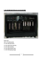
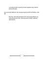
Ceriatone
SSS
100W all-tube guitar amplifier
User’s Manual
1
Thank you for the purchase of your Ceriatone SSS guitar amplifier!
Here, we hope to explain how best to use your new amp.
Table of Contents
1) About the SSS……………...…………………………………………………………………………………………page 2
2) Quick setup……………………………………………………………………………………………………………page 3
3) Front Panel controls………………………………………………………………………………………………….page 4
4) Rear Panel controls…………………………………………………………………………………………………..page 8
5) Tube compliment and external bias jacks and adjustment………………………………………………………page 12
6) Frequently Asked Questions………………………………………………………………………………………...page 17
1) About the SSS 100W and 50W amplifiers
The release of our Overtone series of amplifiers has been overwhelmingly popular, and the support of customers such as you
has instigated the release of currently over ten different versions within the series. In addition, we have released the Kleinulator and C-lator effects loop interfaces specifically for use with our Overtone amplifiers. We have been pleased to provide
many players access to our unique take on these legendary amplifiers.
At this point, we have finally been able to release our most anticipated model in this series – the SSS. We have spent the
better part of 10 years researching this amplifier, yet the information available was limited and understandably closely guarded.
However, in the last two years, we were given a once in a lifetime opportunity that we could not pass up. After tens of
thousands of dollars in R&D, hundreds of man-hours, and careful custom-made parts revisions, we are able to release to you a
clone of one of the most sought after amplifiers in history. While few specimens exist, ours represents a particular 100W model
that absolutely blew us away with its complex, three-dimensional clean tone, and it’s ability to rock when needed. After
experiencing this circuit first hand, we knew we had something special.
2
In order to produce the most sonically faithful recreation possible, we continued to pour additional time, manpower, and money
into many custom parts specifically for this amplifier. In our humble opinion, the result of our labors is truly sublime and an
entirely unique circuit compared to our OTS series. Most of all, we hope the SSS fills the gap you have been searching for and
becomes an integral part of your tone equation to exhilarate your playing and music.
Rock on!
-
Nik Azam
2) QUICK SETUP (for instant gratification)
1) Plug your guitar using a 1/4” instrument cable into the INPUT on the left of the front panel
2) Plug a suitable power cable from the SSS’s rear panel A.C. MAINS cable inlet to your wall power receptacle
3) Plug the SSS into your speaker cabinet using 1/4” speaker cable
4) Set the IMPEDENCE selector to the match the impedance of your speaker cabinet
5) Plug the footswitch cable into the FOOT PEDAL jack on the rear panel of the amplifier
6) Set the FET and PAB switches on the rear panel in the PEDAL position
7) Set the LNFB switches on the rear panel in the lower position
8) Set all rotary controls on the front panel to 12:00 (clock face)
9) Turn MASTER control to about 9:00 (clock face)
10) Set front panel BRIGHT, MID BOOST, and DEEP switches in the down position
11) Set front panel ROCK / JAZZ switch in the up position (ROCK)
12) Set rear panel MAINS switch in the ON position (with adjacent switch to STANDBY) for 30 seconds to allow tube
filaments to warm up
13) Set rear panel OPERATE / STANDBY switch to OPERATE
14) ROCK!!!!!!
3
3) FRONT PANEL CONTROLS
From left to right:
1) INPUT ¼” instrument jack
2) FET control
3) GAIN control
4) BRIGHT three-way toggle switch
5) DEEP two-way toggle switch
6) MID BOOST two-way toggle switch
7) ROCK / JAZZ two-way toggle switch
8) TREBLE control
9) MIDDLE control
10) BASS control
11) HIGH (FILTER) 7-way rotary switch
12) LOW (FILTER) 7-way rotary switch
13) SEND (REVERB) control
14) RETURN (REVERB) control
15) MASTER control
16) PRESENCE control
17) ON / OFF (POWER) two-way switch
18) OPERATE / STANDBY two-way switch
19) INDICATOR LED
4
INPUT jacks provide two tonal options in a single jack. If the FET mode is not engaged, the INPUT is a typical, 1megaohm
input impedance as seen on most guitar amplifiers. If the FET mode is engaged, the guitar signal will pass through a high-input
impedance, low-output impedance JFET gain stage before hitting the first triode tube stage. Originally, the FET circuit was
designed for piezo pickups without an onboard preamplifier. Since then, it has provided players a unique option for fine-tuning
their tone. In the SSS amplifier, experiment with using the FET mode as a clean boost to overdrive the amp for one of the most
pleasing crunch tones you’ll ever hear.
FET adjusts the amount of signal boost coming out of the JFET booster. Set it at unity gain for a slightly brighter, more
articulate tone. Set it higher to use a clean boost to overdrive the SSS’s preamp or as a solo boost.
GAIN adjusts the signal strength coming out of the tonestack, and going into the second tube stage. Think of this as a
traditional gain control in a primarily clean amplifier.
BRIGHT is a high-frequency boost that can be used to add sparkle to your tone in both clean and overdrive modes. This high
frequency boost is more prominent as VOLUME is turned down. With the toggle switch in the UP position, BRIGHT is on and
at a minimum level. In the middle position, BRIGHT is off. The bottom position is BRIGHT on and provides the brightest tone.
DEEP is a bass-frequency boost. You can use this to add subharmonics and girth to your tones. Engaging this switch with
single-coil guitars will produce an absolutely stunning piano-like response on the lower strings. With the toggle switch in the UP
position, DEEP is on. In the DOWN position, DEEP is off.
MID BOOST is a midrange-frequency boost. You can use this to add fatness to your tones, or even make single coil guitars
sound thicker and less scooped. We particularly like MID BOOST when using the SSS for crunch tones. With the toggle switch
in the UP position, MID BOOST is on. In the DOWN position, MID BOOST is off.
ROCK / JAZZ adjusts the overall frequency response and voicing of the amplifier. ROCK has a fatter midrange and a deeper,
spongier bottom end. You might find ROCK more familiar territory. JAZZ tightens up the bottom end and adjusts the contour of
the midrange, giving the amplifier more of a hi-fi response. Experiment with both, as great sounds rest in each. With the toggle
switch in the UP position, ROCK is on. In the DOWN position, JAZZ is on.
5
TREBLE adjusts the high frequency response for both clean and overdrive modes. At near-maximum settings, you may also
notice an increase in gain.
MIDRANGE adjusts the mid frequency response for both clean and overdrive modes.
BASS adjusts low frequencies in your amplifier for both clean and overdrive modes.
HIGH (FILTER) represents half of one of the most unique (perhaps mystifying) aspects of the SSS amplifier. In the original
amplifiers, this represented one of the greatest areas of variablility. In the Ceriatone SSS, the HIGH filter control is a 7-way
rotary switch. Turning the switch fully counter-clockwise will bypass the FILTER circuit completely. Turning the control
clockwise will progressively decrease the amount of treble boost present, resulting in a darker sound.
LOW (FILTER) serves as the other half of the filter control, and is an extremely unique EQ control for guitar amplification. The
LOW filter is an inductor based bandpass filter tuned for bass frequencies. Compared to the HIGH filter, this is more subtle,
“sculpting” control that is highly effective and tuning the low frequency response of the amplifier to your cabinet. Fully counterclockwise, the most bass frequencies are preserved. Turning the control clock-wise will progressively decrease the amount of
bass frequencies present, resulting in a slightly thinner, more focused sound.
NOTE – turning the HIGH filter all the way counter clockwise (to the left) will bypass the SSS’s 7-way rotary filter controls.
SEND (REVERB) controls the amount of signal fed into the unique three-tube reverb circuit in the SSS amplifier. The SEND
control will impact the nature of the decay of the reverb, as well as the overall intensity of the reverb circuit. Generally, turning
the SEND control clockwise will increase the time of the reverb trail, creating a longer, more “springy” reverb quality.
RETURN (REVERB) controls the amount of signal from the three-tube reverb circuit as blended back into the preamp circuit.
The RETURN control will generally increase the prominence of the reverb signal compared to the dry signal. Turning the
REVERB control clockwise will make the reverb sound louder compared to the dry signal, creating a more wet, effected sound.
MASTER sets the overall volume of your amplifier.
6
PRESENCE adjusts the high frequency response of the power amplifier using negative feedback. Use this control to add
sparkle and clarity to your tone.
ON / OFF (POWER) two-way toggle switch powers the SSS on and off. With the toggle switch in the UP position, the SSS is
ON. In the DOWN position, the SSS is OFF.
OPERATE / STANDBY applies high voltage to the vacuum tube anodes (and screen grids) during use of the SSS. To ensure
long tube life, first power the unit on with the toggle switch in STANDBY position for approximately 30 seconds. Then switch to
OPERATE to use the SSS. With the toggle switch in the UP position, the SSS is in OPERATE mode. In the DOWN position,
the SSS is in STANDBY mode.
INDICATOR will illuminate when the SSS is powered by turning the rear panel MAINS toggle switch to the ON position. If
INDICATOR does not turn on, check your power cable connections, and then the 4A (3A in 240V countries) slow-blow fuse on
the rear of the unit.
7
4) REAR PANEL CONTROLS
1) HT 1A slow-blow fuse
2) MAINS 4A / 3A slow-blow fuse
3) A.C. MAINS IEC cable inlet
4) BIAS CHECK DMM probe jacks
5) HALF POWER two-way toggle switch
6) SPEAKER OUTPUT ¼” speaker jacks
7) IMPEDANCE three-way rotary selector
8) EFFECTS LOOP RETURN ¼” instrument jack
9) EFFECTS LOOP SEND ¼” instrument jack
10) PAB two-way toggle switch
11) FET two-way toggle switch
12) FOOT PEDAL 5-pin DIN female jack
13) V1B LNFB three-way toggle switch
14) V1A LNFB three-way toggle switch
HT 1A slow-blow fuse – used to protect your amplifier from voltage spikes or excessive current draw. Replace only when
necessary.
MAINS 4A / 3A slow-blow fuse – used to protect your amplifier from voltage spikes or excessive current draw. Replace only
when necessary. 4A is used for amplifiers used with a 120VAC country supply, and 3A is used with 240VAC.
8
A.C. MAINS IEC cable inlet – plug a suitable IEC power cable into this inlet to power your amplifier
BIAS CHECK DMM probe jacks – see Section 5 (page 12) for a thorough explanation on their use and biasing
HALF POWER two-way toggle switch. Use this switch to reduce the output power of the amplifier from 100W to 50W. Doing
so will slightly reduce volume, and change the feel and response of the amplifier slightly. Experiment for best results!
SPEAKER OUTPUT ¼” speaker cable jacks. Use a ¼” speaker cable to connect your speaker cabinet to the amplifier using
these jacks. If you use one speaker cabinet, use the jack labeled MAIN. If you want to run two cabinets in parallel, connect the
second cabinet to the amplifier using the jack labeled EXTENSION.
NOTE – never turn your amplifier to OPERATE mode without connecting the amplifier to a speaker cabinet or suitable dummy
load! Failing to do so may damage your amplifier!
IMPEDANCE three-way rotary selector. Set this selector to the position that matches the impedance of your speaker cabinet.
NOTE – if you are using two speaker cabinets in parallel (ex – two 16 Ohm cabinets), set the impedance selector to half that of
a single cabinet (in this case, 8 Ohms).
EFFECTS LOOP RETURN ¼” instrument jack can be used to directly interface the power amp of the SSS, thereby bypassing
the preamp and using the amplifier as a power amplifier. Conversely, this is usually used as the RETURN of the effects loop.
Plug the output of your effects unit, or interface device (ex – C-lator, Klein-ulator) into this jack using ¼” instrument cable. The
effects loop in the SSS amplifier is all passive, like the originals.
EFFECTS LOOP SEND ¼” instrument jack can be used to directly interface the preamp of the SSS, thereby bypassing the
power amplifier and using the SSS as a preamp. Conversely, this is usually used as the SEND of the effects loop. Plug the
input of your effects unit, or interface device (ex – C-lator, Klein-ulator) into this jack using ¼” instrument cable. The effects
loop in the SSS amplifier is all passive, like the originals. If only using the preamp of the SSS, the amplifier still must be
connected to a suitable speaker or passive load.
9
PAB (aka – “PREAMP BOOST”) two-way toggle switch manually switches between boosted and normal configurations. In this
SSS, the PAB accentuates midrange frequencies and attenuates low frequencies, making it great for cutting through during a
solo. Engaged, you will also notice an increase in gain and distortion characteristics. If you are using the foot pedal, set this in
the PEDAL position. If you are not using the included foot pedal, the toggle switch in the MANUAL position switches the SSS to
PREAMP BOOST mode. In the PEDAL position, the SSS is in normal mode.
FET two-way toggle switch manually switches the JFET boost in and out of the circuit. If you are using the foot pedal, set this
in the PEDAL position. If you are not using the included foot pedal, the toggle switch in the MANUAL position switches the SSS
to FET mode. In the PEDAL position, the FET boost is not activated.
NOTE – if the FOOT PEDAL is plugged in, but the PAB and/or FET toggles are in MANUAL, the foot pedal LED indicators will
still light up but functions will not be switched. For the FOOT PEDAL to function, PAB and FET rear panel toggles MUST be in
PEDAL position.
FOOT PEDAL 5-pin DIN female jack is used to connect the foot pedal to the amplifier. Use the foot pedal to control the PAB
and FET modes. Red LED indicates FET activated, and Green LED indicates PAB boost activated.
NOTE – when using the FET boost on the footswitch, you may notice a slight “pop” when you engage the circuit, depending on
your settings. We have gone to great lengths to minimize this pop as much as possible and preserve signal integrity. Anytime
a circuit is engaged before the first gain stage of an amp, any switching noise is amplified hundreds of times through the
preamp circuit. In the SSS, the switching noise is far from problematic, but we wanted to inform you if you do experience it, it is
normal and neither a malfunctioning circuit nor design flaw.
V1B LNFB three-way toggle switch. This controls the amount of negative feedback applied to the second gain stage of the
amplifier. Placing the toggle in the up position defeats the negative feedback, which provides the most gain and harmonic
“bloom”. In the center position, the negative feedback is applied minimally. The bottom position provides the most negative
10
feedback, which results in a cleaner, leaner, and more controllable sound, and is the “standard” SSS setting. Experiment for
your own best results.
V1A LNFB three-way toggle switch. This controls the amount of negative feedback applied to the first gain stage of the
amplifier. Placing the toggle in the up position defeats the negative feedback, which provides the most gain and harmonic
“bloom”. In the center position, the negative feedback is applied minimally. The bottom position provides the most negative
feedback, which results in a cleaner, leaner, and more controllable sound, and is the “standard” SSS setting. Experiment for
your own best results.
11
5) TUBE COMPLIMENT AND EXTERNAL BIAS JACKS AND ADJUSTMENT
From left to right:
V9, V8, V7, V6 – 6L6GC power tube
V5 – 12AX7 / ECC83 (phase inverter)
V4 – 12AX7 / ECC83 (reverb / preamp mixer)
V3 – 12AT7 / ECC81 (reverb driver)
V2 – 12AX7 / ECC83 (reverb send / return)
V1 – 12AX7 / ECC83 (preamp gain stages)
12
13
V9
V8
V7
COM
V6
BIAS POT
In this diagram, we have color-coded three features for simplicity
1) Green arrows = red probe jacks
2) Yellow arrow = black probe jack
3) Blue arrow = bias adjustment potentiometer shaft
To measure your power tube bias, carefully follow these steps with the amplifier in OPERATE and connected to a speaker
load (not doing so may damage your amplifier!):
1) Turn on a digital multimeter (DMM), and set it to read millivolts (mV) in the 100mV range (this will vary from DMM to
DMM)
2) Plug a black probe into the color-coded jack on your DMM, and do the same for a red probe
3) Insert the black probe tip into the black probe jack labeled COM on the rear of the amplifier. This is GROUND.
4) Insert the red probe tip into the red probe jack (green arrow) on the far left according to the picture on page 13. This
measures bias for V6. Right down the value your DMM reads. You might expect a value between 35mV and 45mV.
5) Repeat for the next red probe jack to the right (V7), again the red probe jack one more to the right (V8), and finally the
red probe jack on the far right (V9).
Okay, now I’ve measured my bias. Now what?
To calculate bias, there are two pieces of information you need to know: your amplifier’s power tube plate voltage, and the
published value for maximum plate dissipation for the power tubes used in your amplifier. To save you some time and energy,
here are those two values:
-
Approximate plate voltage for SSS amplifiers
Maximum plate dissipation for 6L6GCs
=
=
450-460VDC
30W
…and now some math. The formula for calculating bias is as follows:
In most cases, amplifiers are biased between 50% and 75% dissipation. We bias the SSS to approximately 35mV-40mV
reading on a DMM.
14
An example is as follows:
You might wonder why your DMM is set to millivolts and not milliamps – simply, we have a 1 Ohm resistor placed between your
probe jacks and ground to convert a current reading to a voltage reading. That way, a bias current of 35mA measures as 35mV
on your DMM.
NOTE – Only set your DMM to mV for measuring bias on the SSS amplifiers. Not doing so may damage your DMM.
Now that you know how to calculate bias, all you need to do is:
1) Follow steps 1-5 on page 12
2) Calculate what bias voltage reading you will set your tubes to (in this case, we will use 35mV)
3) Insert your red probe in the probe jack of the power tube reading somewhere in the middle bias measurement of your
power tubes(variation in bias measurements from tube to tube is to be expected, so selecting one measuring in the
middle will approximate bias for all tubes)
4) Turn the bias potentiometer shaft SLOWLY until your DMM reads 35mV
5) Wait 1 minute
6) Recheck all power tube bias measurements
7) Readjust bias potentiometer shaft if necessary
15
A FEW COMMENTS ON BIASING
Due to the nature of vacuum tube amplification, there are inherent risks when biasing your amplifier. Extremely high voltages
are present, and vacuum tubes reach high temperatures during use.
The risk of electrical shock and/or skin burns should ALWAYS be kept in mind. Therefore, bias at your own risk, and only while
paying attention and taking all precautionary measures.
Biasing should only be done on a clean workbench with no distractions. Do not wear loose clothing or any jewelry. Take your
time, and think carefully before each step.
Even though the bias test points and adjustment are external to reduce risk of electrical shock, all precautions must be taken
while biasing.
Again, bias at your own risk. Ceriatone Amplification is not responsible for any damages or injuries resulting from user biasing.
16
6) FREQUENTLY ASKED QUESTIONS
How do I hook up this thing?
-
See Section 2, beginning on page 3.
When I plug effects into the effects loop, my tone noticeably changes. Sometimes the effects don’t sound quite right. What’s
the deal?
-
Generally, what you’re hearing is a significant mismatching of impedances, and/or an overloading of the effect
unit itself. Most rack-mount units have different input impedance than pedals, and thus can sometimes
function fine without a buffer before them. In addition, some of these rack-mounted effects can pad the
volume they receive, preventing it from overloading. Pedals do not have proper input impedance or padding
ability, and therefore do not play nicely.
-
For best results, an effects loop interface like the C-lator or Klein-ulator should be used with the SSS
amplifier. These units prevent impedance mismatching, as well as provide the ability to pad down the volume
sent to the effects units hence preventing any overloading.
Can I substitute different tube types for the 12AX7/ECC83s or 6L6GCs?
-
Although you can try 12AT7s, 12AU7s, 5751s without any harm, the design is optimized for 12AX7s, and are
therefore the only recommended tube in the preamp positions. Usage of other power tubes (ex – modern
6V6s like Electro-Harmonix, JJ) may be possible, but please first consult Ceriatone Amplification or your local
competent amplifier technician. ONLY USE A 12AT7 / ECC81 IN V3!!!!
What settings do you recommend?
17
- Try setting all controls at 12:00, and adjust MASTER to a suitable volume.
I have the foot pedal plugged in, but it’s not switching functions? The LEDs on the foot pedal still light up though….
-
Make certain the rear toggles for OVERDRIVE and PREAMP BOOST are in the PEDAL positions
I noticed the amplifier has a trimpot on the main board. What does it do?
-
This trimpot adjusts the amount of signal fed into the FILTER circuit. Adjusting this will impact the intensity of
these controls as well as signal strength and noise levels. As such, we do not recommend adjusting this
control from the factory setting.
Do I need to use matched power tubes?
-
Although not necessary, matched power tube sets are recommended for best results.
Do I need to use a matched and balanced phase inverter?
-
It is not necessary. Feel free to experiment with different tubes (of the same type) in your SSS, though!
I’ve read that the components used in this type of amplifier are really important. What is inside my SSS?
-
We use a combination of parts custom-made for us to our specifications (power transformer, output
transformer, choke, high-temperature / low-ESR electrolytic capacitors, inductors, custom Alpha
potentiometers) and those used in the original amplifiers (Vishay/Dale RN65 precision metal film resistors, 1W
carbon film resistors, SBE 6PS polyester film capacitors, high-quality ceramic disc capacitors, Belton tube
sockets, Alpha potentiometers). We prefer high-quality enclosed Cliff (built in the UK) jacks to the open-style
Switchcraft jacks used in the originals and many clones. Finally, we occasionally use NOS components from
18
our vast surplus parts collection in locations they work well and complement the voicing or enhance the
performance of the amplifier.
I like to use rack-mounted multieffects units. What is the output level straight from the EFFECTS LOOP SEND jack, -10dB or
+4dB?
-
While not exact, -10dB is a better approximation than +4dB. The actual output level will depend on your
settings, particularly the volume controls. +4dB is usually reserved for recording/P.A. equipment with
balanced connections.
19