1
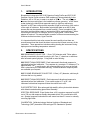
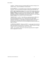
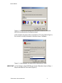
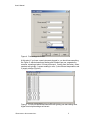
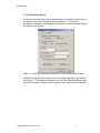
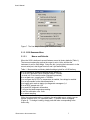
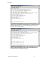
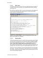
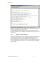
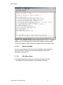
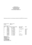
QSP-2150
and
QCP-2150
Submersible PAR Sensors
with ASCII Output
User's Manual
Biospherical Instruments Inc.
5340 Riley Street
San Diego, CA 92110-2621 USA
Phone (619) 686-1888
Fax: (619) 686-1887
E-mail: [email protected]
www.biospherical.com
Version QSP_QCP2150_Manual.DOC
Date Printed: 3/13/2007
User’s Manual
NOTICE
The information contained in this document is subject to change without notice.
BIOSPHERICAL INSTRUMENTS MAKES NO WARRANTY OF ANY KIND WITH REGARD
TO THIS MATERIAL, INCLUDING, BUT NOT LIMITED TO, THE IMPLIED WARRANTIES
OF MERCHANTABILITY AND FITNESS FOR A PARTICULAR PURPOSE. Biospherical
Instruments shall not be liable for errors contained herein or for incidental or consequential
damages in connection with the furnishing, performance, or use of this material.
This document contains proprietary information that is protected by copyright. All rights are
reserved. No part of this document may be photocopied, reproduced, or translated into
another language without the prior written consent of Biospherical Instruments Inc.
Copyright © 2007 by Biospherical Instruments Inc.
First Edition: March 2007
BIOSPHERICAL INSTRUMENTS INC.
ii
User’s Manual
LIMITED WARRANTY
BIOSPHERICAL INSTRUMENTS INC. warrants this product to be in good working order for
a period of one (1) year parts and ninety (90) days labor from the date of purchase. Should
this Product fail to be in good working order at any time during the above stated warranty
period, Biospherical Instruments Inc. will, at its option, repair or replace this Product at no
additional charge except as set forth below. Repair parts and replacement Products will be
furnished on an exchange basis and will be either reconditioned or new. All replacement
parts and Products become the property of Biospherical Instruments Inc. This limited
warranty does not include service to repair damage to the Product resulting from accident,
disaster, misuse, abuse, or non-Biospherical Instruments Inc. modification of the product.
Limited warranty service may be obtained by delivering the Product during the warranty
period to Biospherical Instruments Inc. at its San Diego, California, Service Center, showing
proof of purchase. If this Product is delivered by mail, you agree to insure the Product or
assume risk of loss or damage in transit; to prepay shipping charges to the San Diego,
California, Service Center; to use the original shipping container or equivalent; and to pay
for return shipping charges.
ALL EXPRESS AND IMPLIED WARRANTIES FOR THIS PRODUCT INCLUDING THE
WARRANTIES OF MERCHANTABILITY AND FITNESS FOR A PARTICULAR PURPOSE,
ARE LIMITED IN DURATION TO THE ABOVE WARRANTY PERIOD, AND NO
WARRANTIES, WHETHER EXPRESSED OR IMPLIED, WILL APPLY AFTER THIS
PERIOD. SOME STATES DO NOT ALLOW LIMITATIONS ON HOW LONG, AN IMPLIED
WARRANTY LASTS, IF SO THE ABOVE LIMITATIONS MAY NOT APPLY TO YOU.
IF THIS PRODUCT IS NOT IN GOOD WORKING ORDER AS WARRANTED ABOVE,
YOUR SOLE REMEDY SHALL BE REPAIR OR REPLACEMENT AS PROVIDED ABOVE.
IN NO EVENT WILL BIOSPHERICAL INSTRUMENTS INC. BE LIABLE TO YOU FOR ANY
DAMAGES, INCLUDING ANY LOST PROFITS, LOST SAVINGS OR OTHER INCIDENTAL
OR CONSEQUENTIAL DAMAGES ARISING OUT OF THE USE OR INABILITY TO USE
SUCH PRODUCT, EVEN IF BIOSPHERICAL INSTRUMENTS INC. HAS BEEN ADVISED
OF THE POSSIBILITY OF SUCH DAMAGES. NOR WILL BIOSPHERICAL INSTRUMENTS
INC. BE LIABLE FOR ANY CLAIM BY ANY OTHER PARTY.
SOME STATES DO NOT ALLOW THE EXCLUSION OR LIMITATION OF INCIDENTAL OR
CONSEQUENTIAL DAMAGES FOR CONSUMER PRODUCTS, SO THE ABOVE
LIMITATIONS OR EXCLUSIONS MAY NOT APPLY TO YOU.
THIS WARRANTY GIVES YOU SPECIFIC LEGAL RIGHTS, AND YOU MAY ALSO HAVE
OTHER RIGHTS THAT MAY VARY FROM STATE TO STATE.
BIOSPHERICAL INSTRUMENTS INC.
iii
User’s Manual
TABLE OF CONTENTS
INITIAL INSPECTION AND SHIPPING PROCEDURES ..............................................V
PRECAUTIONS .....................................................................................................................V
1.
INTRODUCTION ............................................................................................................1
2.
SPECIFICATIONS ..........................................................................................................1
3.
OPERATION AND MAINTENANCE...........................................................................3
3.1.
OPERATING THE 2150 (APPLIES TO QSP AND QCP).................................................. 3
3.1.1.
Connecting to the 2150 using HyperTerminal
3.1.2.
Finish Port Setup.
3.1.3.
2150 Embedded Menu
3.1.3.1. Menus and Defaults
3.1.3.2. Unit ID and Serial Number (Password Protected)
3.1.3.3. Setting Log Output and Auxilliary Channels
3.1.3.4. Quiet mode
3.1.3.5. Sampling Rate
3.1.3.6. Reporting Calibrated Values
3.1.3.7. Setting a Preamble Message
3.1.3.8. Restart Sampling
3.1.3.9. Other Menu Items.
3
6
7
7
8
9
11
11
12
14
15
15
3.2.
MAINTENANCE............................................................................................................... 16
3.3.
LEAKAGE OR FLOODING: WHAT TO DO .................................................................. 16
3.4.
CABLE DRAWING........................................................................................................... 17
BIOSPHERICAL INSTRUMENTS INC.
iv
User’s Manual
INITIAL INSPECTION AND SHIPPING PROCEDURES
This instrument was carefully inspected mechanically and electrically, and was calibrated
before shipment. It should be free of mars or scratches and in perfect operating condition
upon receipt. To confirm this, the instrument should be inspected for physical damage
incurred in transit. If the instrument was damaged in transit, file a claim with the carrier.
Check the instrument for proper operation as outlined in this manual. If there is damage or
deficiency, see the Warranty in the preface of this manual.
WARNING: Read the sections on installation, operation and
maintenance before attempting to operate or disassemble the
instrument.
Retain original packing material for shipment to the factory. The instrument must be
carefully wrapped and cushioned with appropriate packing material before it is shipped.
PRECAUTIONS
PROTECT THE UNDERWATER CABLE AND CONNECTOR. The sensor’s underwater
connector is the most vulnerable part of the system. Protect all connector contacts from
moisture, during use and while in storage. Do not step on the cable, or strike it while it is
plugged into the instrument.
PROTECT THE INTEGRATED CIRCUITS. A person walking across a carpet on a dry day
can generate a static charge of more than 10,000 Volts. The resulting discharge can
destroy an integrated circuit. Use standard anti-static equipment any time the instrument is
opened up and the components are removed.
AVOID SHADOWS AND REFLECTIONS. During deployments or installations, be careful to
keep the instrument away from reflections and shadows caused by surrounding structures.
An underwater instrument package should be positioned for lowering on the side of the ship
toward the sun. If the instrument is lowered into the shadow created by the ship, this
shadow will contaminate measurements for depths up to 100 meters. When positioning a
ship and deploying an underwater sensor, wind direction is also a factor since the wind or
wind-driven currents can push the ship over the sensor when it is being lowered, thereby
causing shadowing. A surface sensor should be mounted so that it will not be shaded by, or
experience reflections from, surrounding structures.
CARRY SPARE CABLE AND POWER SUPPLIES. For extended operations, it is strongly
recommended that the user maintain spare cables.
PROTECT THE SCALAR COLLECTOR. The Teflon® ball and mount are critical optical
components. They have been aligned at the factory before calibration. It is possible to
remove the ball, but this voids the calibration. The stainless steel mount contains a quartz
light pipe and is FRAGILE. If you suspect damage, or if the ball has been removed, contact
the factory.
BIOSPHERICAL INSTRUMENTS INC.
v
User’s Manual
1.
INTRODUCTION
Biospherical Instruments QSP-2150 Quantum Scalar Profiler and QCP-2150
Quantum Cosine Profiler measure PAR irradiance (Photosynthetically Active
Radiation, 400 to 700 nm) in water to a depth of 2000 m. The only difference
between the two model types is the irradiance collector geometry: a QSP has a
scalar (spherical) collector that responds equally to light from almost any
direction; a QCP has a collector that responds to light as a function of the cosine
of the angle of incidence. Both models output digital data as an ASCII data
stream and may be operated from a serial terminal. Power is supplied by the
host serial communications port (or appropriate USB to serial converter). When
connecting the sensor to a USB port, use of a “High-Speed” USB-to-Serial
adapter is required. This manual details operation of these two sensorsusing the
Windows terminal emulator, HyperTerminal.
It is important that this instruction manual be read carefully since there are
several precautions that should be taken to ensure the inherent accuracy of the
instrument. These precautions include avoiding shading the instrument during
deployment and avoiding temperature extremes.
2.
SPECIFICATIONS
QSP IRRADIANCE COLLECTOR: 1.9 cm (3/4") diameter solid Teflon sphere
optically connected to the main housing by a 2.5 cm (1") aluminum or stainless
steel encased quartz light pipe. O-ring seal to main housing.
QSP DIRECTIONAL RESPONSE: Each instrument's directional response is
optimized before final calibration. The response is a constant ±7% between 0o to
approximately 135o in zenith angle, with response falling off to zero as the light
field is obscured by the instrument housing. Individual detector response plots
are available upon request.
QCP COSINE IRRADIANCE COLLECTOR: 1.15cm (.45”) diameter, solid acrylic
collector that is o-ring sealed.
QCP DIRECTIONAL RESPONSE: Each instrument's directional response is
optimized before final calibration. From zenith angles of 0° to 85°, the
instrument’s directional response follows the cosine law to ±6%.
PHOTODETECTORS: Blue-enhanced high-stability silicon photovoltaic detector
with dielectric and absorbing glass filters assembly.
SPECTRAL RESPONSE: Equal (better than ±10%) quantum response from 400
nm to 700 nm with response sharply attenuated above 700 nm and below 400
nm. Spectral response induced errors will cause less than 5% errors in naturally
occurring light fields.
CALIBRATION: Calibrated using a National Institute of Standards and
Technology (NIST)-traceable 1000-watt type-FEL Standard of Spectral
BIOSPHERICAL INSTRUMENTS INC.
1
User’s Manual
Irradiance. Calibration factors are immbeded within the sensor housing as nonvolatile memory. Annual recalibration is recommended.
ENVIRONMENTAL: O-ring sealed and uses a high quality oceanographic-type
connector. The housing and sensor should be rinsed in fresh water after use.
DEPTH: QSP: Aluminum housing: Not to exceed 2000 (two thousand) meters.
Plastic housing: Not to exceed 100 (one hundred) meters. QCP: Aluminum
housing: Limited by the depth rating of the underwater connector. Standard
connectors are 6800 m; high pressure connectors are rated for full ocean depths.
Plastic housing: Not to exceed 100 (one hundred) meters.
TEMPERATURE: -2 to 35°C. The 2150 has a small temperature coefficient of
sensitivity (typically less than 0.15%/°C) and a small zero or dark signal
temperature coefficient. For this reason, the instrument should not be left out in
the hot sun. If the instrument does become overheated, allow it to sit in the
surface water for a few minutes to come into temperature equilibrium before you
begin your profile.
POWER REQUIREMENTS: Requires 6-12VDC. In many cases (but not all), the
power requirements can be met by a PC serial port. The QSP reports the supply
voltage to assist in maintaining proper power to the sensor.
CABLE: The underwater cable must be purchased separately and is supplied
with the appropriate connectors.
BIOSPHERICAL INSTRUMENTS INC.
2
User’s Manual
3.
OPERATION AND MAINTENANCE
3.1. OPERATING THE 2150 (APPLIES TO QSP AND QCP)
Note: Before leaving for the field, it is best to fully bench-test the sensor with
your host computer. If the system does not operate properly, consult the factory
for assistance.
The 2150 is very simple to use. You need only plug it into a working and
properly configured serial port. No batteries required!
Communications with the sensor require no special application except a serial
terminal emulator such as HyperTerminal, and all operations are performed
through a simple menu system embedded in the sensor. The following sections
show the initial steps for setting up the sensor.
When you deploy the instrument, make sure that it is lowered so that the
sensor does not pass through the ship's shadow.
CAUTION: Exercise caution when deploying the instrument in very strong
currents. Also, the boat operator or Captain must be notified when lowering any
instrument where it may become caught in the ship's propeller.
3.1.1. CONNECTING TO THE 2150 USING HYPERTERMINAL
Many Windows-based systems launch HyperTerminal from Start-ProgramsAccessories-Communications-Hyperterminal (Figure 1).
Figure 1. The HyperTerminal interface window.
When you first launch HyperTerminal, a Wizard will run that helps set up the
serial connection to a port (Figure 2). These settings can be saved in an .ht file
that can be referenced later. In this example, the file will be called QSP2150.ht
BIOSPHERICAL INSTRUMENTS INC.
3
User’s Manual
Figure 2. Settings for connecting to the 2150 will be saved to a file called
QSP2150.ht using the New Connection wizard.
In this example, the sensor will be connected to a PC using COM1 (Figure 3).
Do not enter or modify information in the other boxes, if available.
Figure 3. In this example, the sensor will be connected to COM1.
IMPORTANT: for Port Settings, select 9600 Bits per second, 8 Data bits, None for Parity, 1
Stop bit and None for Flow control (Figure 4).
BIOSPHERICAL INSTRUMENTS INC.
4
User’s Manual
Figure 4. Port settings for COM1.
At this point, if you have a new instrument plugged in, you should see something
like Figure 5, which shows three floating point numbers per row, separated by
commas, repeating at about 10 lines per second. Coming from the factory, these
numbers are typically 1) sensor reading in volts, 2) circuit board temperature, and
3) supply voltage (Figure 5).
Figure 5. A new (uncustomized) instrument will typically just start talking when
HyperTerminal port settings are correct.
BIOSPHERICAL INSTRUMENTS INC.
5
User’s Manual
3.1.2. FINISH PORT SETUP.
At this point the sensor can “talk” to the serial port, but HyperTerminal is not yet
configured to allow the computer to “talk” to the sensor. To finish the
configuration of the port, use the mouse to navigate to File-Properties and select
the Settings tab (Figure 6).
Figure 6. Connection Properties, Settings tab. Set you port to match these.
And finally, press the ASCII Setup button on the lower right side of the Settings
tab (Figure 7). The important checkbox here is to Echo typed characters locally.
Say OK to accept the settings. And OK again to leave the properties dialog box.
BIOSPHERICAL INSTRUMENTS INC.
6
User’s Manual
Figure 7. The final step is Echo typed characters locally.
3.1.3. 2150 EMBEDDED MENU
3.1.3.1.
Menus and Defaults
When the 2150 is delivered, several features are set to factory defaults (Table 1).
The two most noteworthy are that the output is set to Volts, and that the
instrument is set for Quiet Mode. Setup like this, just plug the instrument in to the
correct serial port, start HyperTerminal, and it just starts talking.
Table 1. Menu entries and factory default settings typical for a 2150 delivery.
A to set number of samples averaged before update: 12
C to set the Calibration Factor for digital output: 1.000000
I to send unit ID and serial number (password protected)
K to set dark zero, currently dark = .000000v.
O to configure the OUTPUTs, temperature is enabled, line voltage is enabled
P to set a preamble for the data transmission =
Q to toggle quiet mode at startup (no diagnostic messages=1): 1
R to set ADC sample rate: 125
S to send ADC diagnostic information
T will give the latest temperature reading
U sets the calibration units: Volts
X to restart sampling
While the instrument is talking, to display the embedded menus, simply type an
escape character (ESC) or a question mark (“?”) and the menu will appear
(Figure 8). To change a setting, simply press the letter corresponding to the
menu entry.
BIOSPHERICAL INSTRUMENTS INC.
7
User’s Manual
Figure 8. Hitting ESC or “?” will interrupt the data display and show the
embedded command menu.
3.1.3.2.
Unit ID and Serial Number (Password Protected)
Menu item I (Figure 9) is password protected to preclude accidental changes of
the sensor model and the serial number. The password is always “Andrew” and
it is case-sensitive (capital A required).
Figure 9. Press I to begin a dialog that controls the instrument ID string and
serial number. The password is “Andrew” (case sensitive, no quotation marks).
BIOSPHERICAL INSTRUMENTS INC.
8
User’s Manual
Press I to begin the dialog that controls the instrument ID string and serial
number. The system will prompt you to “Send password and string.” Type
“Andrew” (this is case sensitive) and press Enter. The system will respond with a
prompt to enter the instrument ID string and serial number. In this example, the
instrument is a QSP2150, serial number 50150 (Figure 10).
Figure 10. After accepting the password (Andrew), the system needs an ASCII
string for the model and serial number. In this case, the model is QSP2150 and
the serial number is 50150.
3.1.3.3.
Setting Log Output and Auxilliary Channels
The 2150 is capable of producing a measurement that is the log of the light
reading (Figure 11). This option allows matching the output from a CTD fitted
with a log-output QSP-200L or QSP-2300. Type N or Y as needed.
Earlier, Figure 5 showed a typical data string from a newly delivered 2150. In
each row, the first number is the light reading, the second is the circuit board
temperature, and the third is the supply voltage to the sensor. The last two
numbers are largely useful for trouble-shooting problems, but may be
superfluous for other purposes. Type Y or N to include or exclude these
numbers in the output data stream (Figure 12). If you press N for both auxiliary
channels, the output will consist of only one number per light reading.
BIOSPHERICAL INSTRUMENTS INC.
9
User’s Manual
Figure 11. The 2150 is capable of outputting the log of the reading. This option
allows matching the output from a CTD fitted with a log-output QSP-200L or
QSP-2300. Type N or Y as needed.
Figure 12. Lastly, you can turn on or off the instrument internal maintenance
channels, temperature and supply voltage. Type Y or N as desired. The
software will echo your choice before moving on.
BIOSPHERICAL INSTRUMENTS INC.
10
User’s Manual
3.1.3.4.
Quiet mode
For instance, Quiet mode (Q) turns off the menu dialog when power is applied. If
you want to see the menu on startup, you can disable Quiet mode by pressing
the Q (Figure 13)
Why would you want Quiet mode? If you are acquiring data to a data logger and
you do not want the startup menu dialog, then turn on Quiet mode and the
system will start up sending data alone.
Figure 13. Quiet mode is a toggle. Press Q to change from on to off or back
again (note message at top of window).
3.1.3.5.
Sampling Rate
The final rate that data are taken is a function of the rate that the analog-to-digital
converter (ADC) is running (menu item R) and the number of samples averaged
into a reported measurement (menu item A). The factory default for the ADC is
125 Hz. If the number of samples used in an average measurement is 12
(factory default), then the reported data rate will be about 10 Hz, which is the
time constant of the optical sensors. If the number of samples contributing to the
average is set to 125 (Figure 14), then the reported data rate will be about 1 Hz.
There is no “correct” combination, but some settings will result in less noisy data
than others. The factory recommends you leave the ADC rate at 125 and adjust
the number of samples used in the average to achieve the data volume you want
for the current sampling conditions.
BIOSPHERICAL INSTRUMENTS INC.
11
User’s Manual
Figure 14. Use menu item A to select the number of readings used to calculate a
reported average sample.
3.1.3.6.
Reporting Calibrated Values
All 2150s from Biospherical are calibrated prior to leaving the factory. This
information includes a calibration (scale) factor that relates the voltage from the
sensor to the measurement units, and a dark zero (offset) value as measured in
our darkroom during the calibration. The relationship is:
Reading [units] = (Reading [volts] – Dark [volts])/Scale [volts per units]
Because of the variablility in the dark value, the factory default 2150 is delivered
reporting volts without subtracting a dark offset. However, the sensor can be set
to report light units directly. To do this, first make a note of the dark offset
voltage. Carefully cover the sensor completely (aluminum foil works very well for
this). Now, interrupt the data using ESC or ? and change the dark offset value
using menu item K (Figure 15). Following the prompt, press Enter and the
sensor will automatically record 20 seconds of dark data, and set the offset for
the average value.
If you want to reset the dark value to zero, push the number “0” instead of Enter.
BIOSPHERICAL INSTRUMENTS INC.
12
User’s Manual
Figure 15. Pressing menu item K will automatically record 20 seconds of data
and use the average as the dark voltage offset. If you press “0” instead of Enter,
any existing value will be reset to zero.
Next, set the calibration factor (the scale) using menu item C (Figure 16). The
entry must be in the format d.dddddd where the “d” is a numerical digit. We
know that the measurement does not have 6 decimal places of accuracy.
However, limitations in the compiler for the software force 6 places of precision.
The same limitation precludes reporting data in quanta.
Lastly, it is a good idea to change the calibration label to reflect the actual units
that are reported. Pressing menu item U allows you to just type in the label (e.g.
uE/m2.s for microEinsteins per meter squared per second).
BIOSPHERICAL INSTRUMENTS INC.
13
User’s Manual
Figure 16. Using menu item C, the calibration factor supplied by the factory can
be entered using the required number format.
To return the instrument to the factory default (volts), simply use menu item C
and enter a calibration factor of 1.000000. Don’t forget to change menu item U to
“Volts” as well.
3.1.3.7.
Setting a Preamble Message
The 2150 has a feature that allows you to add a text message to the start of each
line of data, called a “preamble.” This is especially useful when storing a time
series of measurements or if you have multiple 2150s. Press ESC or ? to
interrupt the data stream, and press menu item P to set the preamble text (Figure
17). Don’t forget to add a trailing comma (“,”) if you need to parse the preamble
from the reading.
BIOSPHERICAL INSTRUMENTS INC.
14
User’s Manual
Figure 17. The preamble for data in this series will be set to “Unit_1,.” Note the
trailing comma to help separate this text from the reading in post-processing.
To remove a preamble, select P and enter a blank response (just press Enter).
3.1.3.8.
Restart Sampling
From the menu display, the instrument will automatically restart sampling in
about 10 seconds. However, you can restart sampling from the menu
immediately by pressing “X.”
3.1.3.9.
Other Menu Items.
S will display engineering information concerning the state of the ADC
T will display the current temperature of the printed circuit board.
BIOSPHERICAL INSTRUMENTS INC.
15
User’s Manual
3.2. MAINTENANCE
When you are finished with your deployment, rinse the sensor with fresh water.
Storing the instrument with residual salt drops will ruin the connectors and
corrode and pit the metal surfaces.
The Teflon® sphere may become dirty during normal use. Do not attempt to
rotate or remove the collector sphere on a QSP or the sensor calibration
will be altered. Simply clean the diffuser gently using a soft tissue or towel and
warm water, soap or a solvent such as acetone or alcohol. Do not use acids,
abrasive cleaners or brushes as this will mar the surface of the sphere and void
the instrument's calibration. Should the sphere become damaged or heavily
soiled, return the instrument to the factory for service and recalibration.
The instrument requires no other maintenance except that O-rings should be
replaced annually when the instrument is calibrated (consult factory for details).
The optical section of the instrument should not be disassembled since this will
void the calibration of the instrument.
If the instrument is actively used, then an annual calibration is suggested.
Contact the factory for details.
3.3. LEAKAGE OR FLOODING: WHAT TO DO
The instrument has been engineered to be waterproof to a depth of 2000 meters.
In the event the instrument leaks, carefully re-package all components and
immediately return them to our factory! Note: Any disassembly of the optical
components will change the calibration of the instrument.
BIOSPHERICAL INSTRUMENTS INC.
16
User’s Manual
3.4. CABLE DRAWING
BIOSPHERICAL INSTRUMENTS INC.
17