1
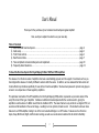
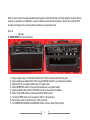
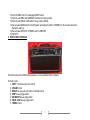
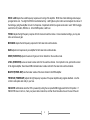
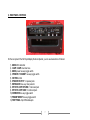
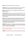
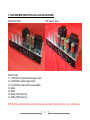
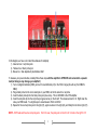
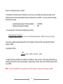
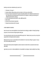
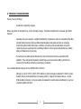
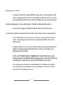
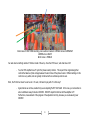
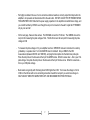
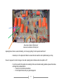
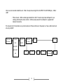
Ceriatone Overtone Special His Royal Majesty Edition 50W and 100W amplifiers 1 User’s Manual Thank you for the purchase of your Ceriatone Overtone Special guitar amplifier! Here, we hope to explain how best to use your new amp. Table of Contents 1) About the HRM Overtone Special………………………………………..…………………………………………page 2 2) Quick setup……………………………………………………………………………………………………………page 3 3) Front Panel controls………………………………………………………………………………………………….page 4 4) Rear Panel controls…………………………………………………………………………………………………..page 7 5) Tube compliment and external bias jacks and adjustment………………………………………………………page 10 6) Frequently Asked Questions………………………………………………………………………………………...page 14 1) About the Overtone Special His Royal Majesty Edition 100W and 50W amplifiers The release of our Overtone series of amplifiers has been overwhelmingly popular, and the support of customers such as you has instigated the release of currently 8 different versions within the series. In addition, we have released the Klein-ulator and C-lator effects loop interfaces specifically for use with our Overtone amplifiers. We have been pleased to provide many players access to our unique take on these legendary amplifiers. This particular incarnation of the OTS amplifiers, the His Royal Majesty (HRM) edition, represents our personal version of the early „90s circuit of this type of amplifier. It utilizes an additional tonestack placed after the overdrive section, giving the amplifier‟s overdrive more of a British sound than the traditional OTS. The clean channel is very similar to our original OTS, but we removed the feedback on the second stage – resulting in a more dynamic, broader sound. We decided to add even more features to our HRM amplifier, making it one of the most versatile offerings in our OTS series. Features such as Hi and Lo inputs, Deep, Mid Boost, Bright, and Rock/Jazz voicings, as well as a rear-mounted overdrive trim all add to its flexibility. 2 While our work could not have been possible without the gracious information shared over the last decade in the public domain, we hope you appreciate our modifications, component selection, and construction techniques. Most of all, we hope the OTS becomes an integral part of your tone equation to exhilarate your playing and music. Rock on! - Nik Azam 2) QUICK SETUP (for instant gratification) 1) 2) 3) 4) 5) 6) 7) 8) 9) Plug your guitar using a 1/4” instrument cable into the HI input on the lower left of the front panel Plug a suitable power cable from the OTS‟s rear panel MAINS cable inlet to your wall power receptacle Plug the OTS into your speaker cabinet using 1/4” speaker cable Set the IMPEDENCE selector to the match the impedance of your speaker cabinet Plug the footswitch cable into the FOOT PEDAL jack on the rear panel of the amplifier Set the OD and PAB switches on the rear panel in the PEDAL position Turn the OD TRIM control on the rear panel to 10:00 to 11:00 (clock face) Set all rotary controls on the front panel to 12:00 (clock face) Turn POWER AMP MASTER and OVERDRIVE LEVEL controls to about 9:00 (clock face) 3 10) Push VOLUME control in to disengage BRIGHT switch 11) Set front panel DEEP and MID BOOST switches in the down position 12) Set front panel ROCK / JAZZ switch in the up position (ROCK) 13) Set rear panel MAINS switch in the ON position (with adjacent switch to STANDBY) for 30 seconds to allow tube filaments to warm up 14) Set rear panel OPERATE / STANDBY switch to OPERATE 15) ROCK!!!!!! 3) FRONT PANEL CONTROLS On the front panel of the HRM Overtone Special, you can see fourteen items of interest. From left to right: 1) INPUT ¼” instrument jacks (LO and HI) 2) VOLUME control 3) BRIGHT two-way push-pull switch on VOLUME control 4) DEEP two-way toggle switch 5) MID BOOST two-way toggle switch 6) ROCK / JAZZ two-way toggle switch 7) TREBLE control 4 8) MIDDLE control 9) BASS control 10) DRIVE (OVERDRIVE) control 11) LEVEL (OVERDRIVE) control 12) MASTER (POWER AMP) control 13) PRESENCE (POWER AMP) control 14) INDICATOR LED INPUT jacks provide two tonal options, and are taken from the Fender Tweed and „60s Marshall amplifier designs. The LO input provides a slight reduction in your guitar signal to prevent overloading the amplifier circuitry. As a result, this input has lower gain and also sounds slightly darker. The HI input is the “traditional” input, and will provide maximum gain and an unattenuated representation of your guitar‟s frequency response. VOLUME adjusts the signal strength coming out of the tonestack, and going into the second tube stage. Think of this as a gain control primarily for your clean channel, but note it will impact the overdrive mode as well. BRIGHT is a high-frequency boost that can be used to add sparkle to your tone in both clean and overdrive modes, and BRIGHT is located on the VOLUME control in a push-pull potentiometer design. This high frequency boost is more prominent as VOLUME is turned down. With the VOLUME in the pulled out position, BRIGHT is on. In the pushed in position, BRIGHT is off. DEEP is a low-frequency boost. You can use this to add a rich bottom end to both clean and overdrive tones. In the overdrive mode, you‟ll also notice this will make the amp feel slightly spongier and will have more “give” in the response. With the toggle switch in the UP position, DEEP is on. In the DOWN position, DEEP is off. MID BOOST is a midrange-frequency boost. You can use this to add fatness to your clean or overdrive tones, or even make single coil guitars sound thicker and less scooped. We particularly like MID BOOST with the overdrive mode. With the toggle switch in the UP position, MID BOOST is on. In the DOWN position, MID BOOST is off. 5 ROCK / JAZZ adjusts the overall frequency response and voicing of the amplifier. ROCK has a fatter midrange and a deeper, spongier bottom end. You might find ROCK more familiar territory. JAZZ tightens up the bottom end and adjusts the contour of the midrange, giving the amplifier more of a hi-fi response. Experiment with both, as great sounds rest in each. With the toggle switch in the UP position, ROCK is on. In the DOWN position, JAZZ is on. TREBLE adjusts the high frequency response for both clean and overdrive modes. At near-maximum settings, you may also notice an increase in gain. MIDRANGE adjusts the mid frequency response for both clean and overdrive modes. BASS adjusts low frequencies in your amplifier for both clean and overdrive modes. DRIVE (OVERDRIVE) adjusts the amount of gain, and in turn distortion in the overdrive mode. LEVEL (OVERDRIVE) serves as master volume control for the overdrive channel. It is important to note, just like this version of the original amplifier, there indeed ARE individual master volume controls for the clean and overdrive channels. MASTER (POWER AMP) sets the master volume of the clean channel in the HRM amplifier. PRESENCE (POWER AMP) adjusts the high frequency response of the power amplifier using negative feedback. Use this control to add sparkle and clarity to your tone. INDICATOR will illuminate when the OTS is powered by turning the rear panel MAINS toggle switch to the ON position. If INDICATOR does not turn on, check your power cable connections, and then the 2A slow-blow fuse on the rear of the unit. 6 4) REAR PANEL CONTROLS On the rear panel of the His Royal Majesty Overtone Special, you can see twelve items of interest. 1) MAINS IEC cable inlet 2) 3 AMP / 2 AMP slow-blow fuse 3) MAINS power two-way toggle switch 4) OPERATE / STANDBY two-way toggle switch 5) OD TRIM control 6) SPEAKER OUTPUT ¼” speaker jacks 7) IMPEDANCE three-way rotary selector 8) EFFECTS LOOP RETURN ¼” instrument jack 9) EFFECTS LOOP SEND ¼” instrument jack 10) OVERDRIVE two-way toggle switch 11) PREAMP BOOST two-way toggle switch 12) FOOT PEDAL 5-pin DIN female jack 7 MAINS IEC cable inlet – plug a suitable IEC power cable into this inlet to power your amplifier 3 AMP / 2 AMP slow-blow fuse – used to protect your amplifier from voltage spikes or excessive current draw. Replace only when necessary. 3A is used for amplifiers used with a 120VAC country supply, and 2A is used with 240VAC. MAINS two-way toggle switch powers the OTS on and off. With the toggle switch in the UP position, the OTS is ON. In the DOWN position, the OTS is OFF. OPERATE / STANDBY applies high voltage to the vacuum tube anodes (and screen grids) during use of the OTS. To ensure long tube life, first power the unit on with the toggle switch in STANDBY position for approximately 30 seconds. Then switch to OPERATE to use the OTS. With the toggle switch in the UP position, the OTS is in OPERATE mode. In the DOWN position, the OTS is in STANDBY mode. OD TRIM control is part of the original design that controls the amount of signal sent into the first stage of the overdrive circuit. However, this control was traditionally a trimpot inside the amplifier chassis. Different settings on this control can yield dramatically different results to the tone, amount of gain, and feel of the overdrive channel. Increasing the control will increase the gain and compression the overdrive channel yields, and will also impact its frequency response. Decreasing control will decrease the gain and increase dynamics of the overdrive channel. SPEAKER OUTPUT ¼” speaker cable jacks. Use a ¼” speaker cable to connect your speaker cabinet to the amplifier using these jacks. If you use one speaker cabinet, use the jack labeled MAIN. If you want to run two cabinets in parallel, connect the second cabinet to the amplifier using the jack labeled EXTENSION. NOTE – never turn your amplifier to OPERATE mode without connecting the amplifier to a speaker cabinet or suitable dummy load! Failing to do so may damage your amplifier! IMPEDANCE three-way rotary selector. Set this selector to the position that matches the impedance of your speaker cabinet. 8 NOTE – if you are using two speaker cabinets in parallel (ex – two 16 Ohm cabinets), set the impedance selector to half that of a single cabinet (in this case, 8 Ohms). EFFECTS LOOP RETURN ¼” instrument jack can be used to directly interface the power amp of the OTS, thereby bypassing the preamp and using the amplifier as a power amplifier. Conversely, this is usually used as the RETURN of the effects loop. Plug the output of your effects unit, or interface device (ex – C-lator, Klein-ulator) into this jack using ¼” instrument cable. The effects loop in the OTS amplifiers are all passive, like the originals. EFFECTS LOOP SEND ¼” instrument jack can be used to directly interface the preamp of the OTS, thereby bypassing the power amplifier and using the OTS as a preamp. Conversely, this is usually used as the SEND of the effects loop. Plug the input of your effects unit, or interface device (ex – C-lator, Klein-ulator) into this jack using ¼” instrument cable. The effects loop in the OTS amplifiers are all passive, like the originals. OVERDRIVE two-way toggle switch manually switches between clean and overdrive channels. If you are using the foot pedal, set this in the PEDAL position. If you are not using the included foot pedal, the toggle switch in the PEDAL position switches the OTS to OVERDRIVE mode. In the MANUAL position, the OTS is in CLEAN mode. PREAMP BOOST (aka – “PAB”) two-way toggle switch manually switches between boosted and normal configurations. In this series of OTS amplifiers, the PAB accentuates midrange frequencies and attenuates low frequencies, making it great for cutting through during a solo. Engaged, you will also notice an increase in gain and distortion characteristics. If you are using the foot pedal, set this in the PEDAL position. If you are not using the included foot pedal, the toggle switch in the MANUAL position switches the OTS to PREAMP BOOST mode. In the PEDAL position, the OTS is in normal mode. NOTE – if the FOOT PEDAL is plugged in, but the PAB and/or OVERDRIVE toggles are in MANUAL, the foot pedal LED indicators will still light up but functions will not be switched. For the FOOT PEDAL to function, PAB and OVERDRIVE rear panel toggles MUST be in PEDAL. FOOT PEDAL 5-pin DIN female jack is used to connect the foot pedal to the amplifier. Use the foot pedal to control the OVERDRIVE and PREAMP BOOST modes. Red LED indicates OVERDRIVE, and Green LED indicates PREAMP BOOST. 9 5) TUBE COMPLIMENT AND EXTERNAL BIAS JACKS AND ADJUSTMENT 50W Overtone Special 100W Overtone Special From left to right: V1 – 12AX7/ECC83 (clean and overdrive stages 1 and 2) V2 – 12AX7/ECC83 (overdrive stages 3 and 4) V3 – 12AX7/ECC83 (phase inverter for power amplifier) V4 – 6L6GC V5 – 6L6GC V6 – 6L6GC (100W version only) V7 – 6L6GC (100W version only) NOTE the HT fuse, which protects the circuitry from excessive current draw, in the lower right corner. Use 1A Fast Blow only. 10 In this diagram, we have color coded three features for simplicity 1) Green arrows = red probe jacks 2) Yellow arrow = black probe jack 3) Blue arrow = bias adjustment potentiometer shaft To measure your power tube bias, carefully follow these steps with the amplifier in OPERATE and connected to a speaker load (not doing so may damage your amplifier!): 1) Turn on a digital multimeter (DMM), and set it to read millivolts (mV) in the 100mV range (this will vary from DMM to DMM) 2) Plug a black probe into the color-coded jack on your DMM, and do the same for a red probe 3) Insert the black probe tip into the black probe jack (blue arrow). This is GROUND in the OTS amplifier. 4) Insert the red probe tip into the red probe jack (green arrow) on the far left. This measures bias for V4. Right down the value your DMM reads. You might expect a value between 35mV and 45mV. 5) Repeat for the next red probe jack to the right (V5), again one more to the right (V6), and finally that on the far right (V7). NOTE – 50W heads will have two red probe jacks. From this view, the probe jack on the left is for V4 and on the right for V5. 11 Okay, now I‟ve measured my bias. Now what? To calculate bias, there are two pieces of information you need to know: your amplifier‟s power tube plate voltage, and the published value for maximum plate dissipation for the power tubes used in your amplifier. To save you some time and energy, here are those two values: - Approximate plate voltage for OTS series amplifiers = Maximum plate dissipation for 6L6GCs = 440-450VDC 30W …and now some math. The formula for calculating bias is as follows: In most cases, amplifiers are biased between 50% and 75% dissipation. We bias the OTS to approximately 35mV-40mV reading on a DMM. An example is as follows: You might wonder why your DMM is set to millivolts and not milliamps – simply, we have a 1 Ohm resistor placed between your probe jacks and ground to convert a current reading to a voltage reading. That way, a bias current of 35mA measures as 35mV on your DMM. NOTE – Only set your DMM to mV for measuring bias on the OTS amplifiers. Not doing so may damage your DMM. 12 Now that you know how to calculate bias, all you need to do is: 1) Follow steps 1-5 on page 11 2) Calculate what bias voltage reading you will set your tubes to (in this case, we will use 35mV) 3) Insert your red probe in the probe jack of the power tube reading somewhere in the middle bias measurement of your power tubes(variation in bias measurements from tube to tube is to be expected, so selecting one measuring in the middle will approximate bias for all tubes) 4) Turn the bias potentiometer shaft SLOWLY until your DMM reads 35mV 5) Wait 1 minute 6) Recheck all power tube bias measurements 7) Readjust bias potentiometer shaft if necessary A FEW COMMENTS ON BIASING Due to the nature of vacuum tube amplification, there are inherent risks when biasing your amplifier. Extremely high-voltages are present, and vacuum tubes reach high temperatures during use. The risk of electrical shock and/or skin burns should ALWAYS be kept in mind. Therefore, bias at your own risk, and only while paying attention and taking all precautionary measures. Biasing should only be done on a clean workbench with no distractions. Do not wear loose clothing or any jewelry. Take your time, and think carefully before each step. Even though the bias test points and adjustment is external to reduce risk of electrical shock, all precautions must be taken while biasing. Again, bias at your own risk. Ceriatone Amplification is not responsible for any damages or injuries resulting from user biasing. 13 6) FREQUENTLY ASKED QUESTIONS How do I hook up this thing? - See Section 2, beginning on page 3. When I plug effects into the effects loop, my tone noticeably changes. Sometimes the effects don’t sound quite right. What’s the deal? - Generally, what you‟re hearing is a significant mismatching of impedances, and/or an overloading of the effect unit itself. Most rack-mount units have different input impedance than pedals, and thus can sometimes function fine without a buffer before them. In addition, some of these rack-mounted effects can pad the volume they receive, preventing it from overloading. Pedals do not have proper input impedance or padding ability, and therefore do not play nicely. - For best results, an effects loop interface like the C-lator or Klein-ulator should be used with the OTS amplifiers. These units prevent impedance mismatching, as well as provide the ability to pad down the volume sent to the effects units hence preventing any overloading. Can I substitute different tube types for the 12AX7/ECC83s or 6L6GCs? - Although you can try 12AT7s, 12AU7s, 5751s without any harm, the design is optimized for 12AX7s, and are therefore the only recommended tube in the preamp positions. Usage of other power tubes (ex – modern 6V6s like Electro-Harmonix, JJ) may be possible, but please first consult Ceriatone Amplification or your local competent amplifier technician. 14 What settings do you recommend? - Try setting all controls at 12:00, and adjust MASTER to a suitable volume. Set the front toggles to their “off” position, and engage ROCK setting. On the rear of the amplifier, try the OD Trim at about 10-11 o‟clock. Be sure to experiment with the OD trim control, as this has dramatic effects on the feel of the overdrive channel. I have the foot pedal plugged in, but it’s not switching functions? The LEDs on the foot pedal still light up though…. - Make certain the rear toggles for OVERDRIVE and PREAMP BOOST are in the PEDAL positions You mentioned this amplifier has an internal tonestack for the overdrive channel. Where is it and can I change the settings? - Yes, this amplifier has the post-overdrive tonestack. It is located on a separate board near the front panel controls. See following page for a picture with three arrows representing the different controls for Bass, Middle, and Treble. - We highly recommend the use of a non-conductive rubber screwdriver, and only adjust the trimpot when the amplifier is not powered and disconnected from the wall outlet. In this case, your screwdriver is a few millimeters away from about 200VDC. - DO NOT ADJUST THE HRM TONESTACK TRIMMERS WHILE THE AMPLIFIER IS ON! Note that the power supply capacitors in the amplifier can/will still store charge, and you can still be bitten by 450VDC even though the amp isn‟t connected to the wall! Adjust the HRM TRIMMERS only at your own risk! - On the following picture, the ORANGE arrow is the MIDRANGE control, the GREEN arrow is the BASS control, and the BLUE arrow is the TREBLE control. We set MIDRANGE to 12:00-1:00 o‟clock, BASS to 10:00-12:00 o‟clock, and TREBLE to 11:00 o‟clock. 15 Internal view of HRM 100W illustrating post-overdrive tonestack. ORANGE arrow is MIDRANGE GREEN arrow is BASS BLUE arrow is TREBLE I’ve read about something called a PI trimmer inside of the amp. Does the OTS have it, and what does it do? - Yes, the OTS amplifier has a PI (short for phase inverter) trimmer. This is part of the original design that controls the balance of plate voltage between the two triodes of the phase inverter. Different settings on this control are very subtle, and are typically monitored with an oscilloscope and not ears. Hmm, the PI trimmer doesn’t sound as fun. Oh well, I still want to play with it! Is that okay? - Again, before we continue, realize that you are adjusting PLATE VOLTAGE. In this case, your screwdriver is about a millimeter away from about 300VDC. DO NOT adjust this trimmer with the amplifier on!!!! Furthermore, measurement of the progress of the adjustment is tricky, because you are measuring near 300VDC! 16 - We highly recommend the use of a non-conductive rubber screwdriver, and only adjust the trimpot when the amplifier is not powered and disconnected from the wall outlet. DO NOT ADJUST THE PI TRIMMER WHILE THE AMPLIFIER IS ON! Note that the power supply capacitors in the amplifier can/will still store charge, and you can still be bitten by 450VDC even though the amp isn‟t connected to the wall! Adjust the PI TRIMMER only at your own risk! - On the next page, there are three arrows. The ORANGE arrow is the PI trimmer. The GREEN arrow is the test point for measuring the plate voltage at V3A. The BLUE arrow is the test point for measuring the plate voltage at V3B. - To measure the plate voltage at V3, your amplifier must be in OPERATE mode and connected to a dummy (preferable) or a speaker load. Turn the MASTER down to minimum! Set your DMM to the VDC measurement (between 200VDC and 1000VDC), and plug the black probe into the black bias probe jack. Place the red probe on the bare wire at the tip of the GREEN arrow. Write this value down – this is your V3A plate voltage. Now plate the red probe on the bare wire at the tip of the blue arrow. Write this value down – this is your V3B plate voltage. - Best results are typically with V3A being about 6VDC higher than V3B. To increase the voltage to V3A or V3B, turn the trimmer with a non-conducting screwdriver toward the test point you want more voltage on. ONLY ADJUST WHEN THE AMPLIFIER IS OFF AND DISCONNECTED FROM THE WALL! 17 Inside chassis view of HRM 100W. Orange arrow indicates PI trimmer. Blue arrow indicates V3B test point Green arrow indicates V3A test point. Adjusting those trimmers sounds intimidating. Am I missing anything if I don’t experiment with them? - Absolutely not. We adjust each trimmer to ensure the best results for each amplifier leaving our shop. How am I supposed to monitor changes in tone after adjusting internal trimmers while the amplifier is off? - If you find yourself in this position and unwilling to follow recommended safety guidelines, please follow these warnings and recommendations: o Use only non-conductive screwdrivers o Do not adjust trimmers with your guitar strapped on 18 Do not wear loose clothing or jewelry Adjust only in proper lighting Have a clear idea what trimmer you are going to adjust, and how you are going to adjust it Take your time If you need to measure values with your DMM, keep the black probe plugged into the black bias probe when measuring with the red probe, keep your opposite arm bent behind your back measure from above, holding the probe at an angle can cause arcing and shorts KEEP PROBE CLEAR OF ALL POINTS YOU DO NOT WANT TO MEASURE Again, Ceriatone is not responsible for any damages or injuries resulting from user adjustments! o o o o o - Do I need to use matched power tubes? - Although not necessary, matched power tube sets are recommended for best results. Do I need to use a matched and balanced phase inverter? - It is not necessary. Feel free to experiment with different tubes (of the same type) in your OTS, though! I’ve read that the components used in this type of amplifier are really important. What is inside my OTS? - We use a combination of parts custom-made for us to our specifications (power transformer, output transformer, choke, high-temperature / low-ESR electrolytic capacitors) and those used in the original amplifiers (Vishay/Dale RN65 precision metal film resistors, 1W carbon film resistors, SBE 6PS polyester film capacitors, high-quality ceramic disc capacitors, Belton tube sockets, and Alpha potentiometers). We prefer high-quality enclosed Cliff (built in the UK) jacks to the open-style Switchcraft jacks used in the originals and many clones. Finally, we occasionally use NOS components from our vast surplus parts collection in locations they work well and complement the voicing or enhance the performance of the amplifier. 19 I like to use rack-mounted multieffects units. What is the output level straight from the EFFECTS LOOP SEND jack, -10dB or +4dB? - While not exact, -10dB is a better approximation than +4dB. The actual output level will depend on your settings, particularly the volume controls. +4dB is usually reserved for recording/P.A. equipment with balanced connections. This all seems kind of complicated, can you tell me where all of these controls are in the preamp so I have a better idea how to set up my amplifier? Clean and OD Stage 1 Tonestack Input Vol DEEP BRIGHT Clean and OD Stage 2 Master FX Loop ROCK/JAZZ MID BOOST OD TRIM OD Stage 3 PAB 20 Drive OD Stage 4 Internal Tonestack Level