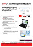
1
TSS TETRA Secury System • Professional communications solution with integrated Personal Emergency Signal and messaging functions • Message and telemetry handling system for the direct notification of all mobile handsets Technical Information Brochure 2 Document type Technical Information Brochure Product TSS: TETRA Secury System Publisher Funkwerk Security Communications GmbH John-F.-Kennedy-Str. 43-53 D-38228 Salzgitter Phone:+49 5341 2235-0 Fax: +49 5341 2235-709 Copyright in this document is protected. All rights reserved. The copying, distribution, translation or conversion of this document in its entirety or any part thereof, whether in electronic or otherwise machine-readable form, is forbidden without the permission of Funkwerk Security Communications GmbH. Subject to change without notice. Suggestions and enquiries ... concerning this technical information brochure must kindly be directed to the above address. Last amendment 14.11.2012 Technical Information Brochure TETRA Secury System 14.11.2012 3 Table of Contents Table of Contents 1 TSS Function Description..................................................................................................................... 5 1.1 What is TSS? ........................................................................................................................ 5 1.1.1 TETRA radio infrastructure ....................................................................................... 6 1.1.2 Functional structure of the TSS ................................................................................ 7 1.2 Certification ........................................................................................................................... 8 1.3 Personal Emergency Signal Functionality ............................................................................ 8 1.4 Messaging ............................................................................................................................ 9 1.5 Requirements for operation ................................................................................................ 12 1.5.1 Schematic depiction of the requirements for operation of a TSS ........................... 13 1.5.2 TETRA Safe ........................................................................................................... 14 1.5.3 Existing TETRA system .......................................................................................... 15 1.6 Operation of the TSS .......................................................................................................... 16 1.6.1 Schematic diagram of the requirements for operation of a TSS ............................. 17 1.6.2 TSS | DSS combination possibilities ....................................................................... 17 1.7 Localisation of persons by ILB and GPS ............................................................................ 18 1.7.1 Schematic diagram of the localisation of a person by GPS .................................... 19 1.7.2 Schematic diagram of the localisation of a person by ILB ...................................... 20 1.8 Alarms ................................................................................................................................. 21 1.8.1 Alarm types ............................................................................................................. 21 1.8.2 Alarm parameters ................................................................................................... 23 1.8.3 Log-in and log-off in the secure Secury mode ........................................................ 24 1.9 Localisation of persons ....................................................................................................... 25 1.10 Alarm reporting .................................................................................................................. 26 1.10.1 Schematic diagram showing an alarm event .......................................................... 27 1.10.2 Processing an alarm ............................................................................................... 28 1.10.3 Expanded alarm procedures .................................................................................. 29 1.11 Scope of supply ................................................................................................................. 29 1.12 Putting into operation ......................................................................................................... 30 2 TSS Server ........................................................................................................................................... 31 2.1 Overview ............................................................................................................................. 31 2.2 Function .............................................................................................................................. 31 2.3 Connection type .................................................................................................................. 33 2.4 Secury Software ................................................................................................................. 33 2.4.1 Overview ................................................................................................................. 33 2.4.2 Configuration and operation ................................................................................... 34 2.4.3 Warden’s Rounds Command and Control System (WGS) ..................................... 34 2.5 Versions of the Guard module ............................................................................................ 35 3 Handsets 3.1 3.2 3.3 3.4 3.5 .............................................................................................................................................. 36 Technical data .................................................................................................................... 36 Handsets | messaging-only function ................................................................................... 37 Handsets | Alarm Function .................................................................................................. 38 microSD card ...................................................................................................................... 39 Accessories and Enhancements ........................................................................................ 39 4 Inductive Localisation Beacon ........................................................................................................... 40 4.1 Overview ............................................................................................................................. 40 4.2 Function .............................................................................................................................. 40 4.3 Properties ........................................................................................................................... 41 4.4 Technical data .................................................................................................................... 42 4.5 Accessories and Spares ..................................................................................................... 43 Technical Information Brochure TETRA Secury System 14.11.2012 4 Table of Contents 5 Application examples .......................................................................................................................... 44 5.1 Cruise liner operator ............................................................................................................ 44 5.1.1 Technical Personnel .............................................................................................. 44 5.1.2 Nautical Personnel ................................................................................................. 44 5.2 Psychiatric detention facility ................................................................................................ 45 5.3 Manufacturer of chemical products ..................................................................................... 46 5.3.1 Production personnel ............................................................................................. 46 5.3.2 Technical Personnel .............................................................................................. 46 5.4 Forensic psychiatrists .......................................................................................................... 46 6 Overview of the TSS performance features ...................................................................................... 48 7 Abbreviations used ............................................................................................................................. 51 Technical Information Brochure TETRA Secury System 14.11.2012 What is TSS? 5 TSS Function Description 1 TSS Function Description 1.1 What is TSS? Funkwerk Security Communications now offers you the full performance package of a professional personal emergency signal system in a TETRA system The TSS is a modern communications platform with integrated and situation-orientated security functions. Professional radio communication and standard telephony functions are combined in this system. The system can be adapted flexibly to the actual needs and grows with your requirements Existing communication, security and IP infrastructures can be integrated without any problem - including, naturally, the DECT-based Funkwerk DSS and UDSS Secury systems. The TETRA Secury System (TSS) is an optimised system comprising a alarm control centre and mobile personal emergency signal devices (FT4 S). A multiplicity of performance features are available for the personal security of your employees. This enables an optimised adaptation to their individual working conditions - even as far as the precise localisation of casualties with the aid of inductive localisation transmitters (beacons) and GPS. Equipped with high performance sensors, these handsets (FT4 S) automatically recognise certain dangerous situations and transmit the appropriate alarm with precise localisation of the scene of the emergency directly to the alarm control centre or on the handsets of the rescue personnel. Alarm events are shown clearly at the alarm control centre, enabling an immediate appreciation of situations even though they may be complex; the proper processing of the alarm can then take place. In addition to the personal emergency signal functionality, the TSS also has messaging features. In this way the operators can also send messages manually. In the event of machine or personal alarms messages can be sent automatically to the TSS handsets. Intrinsically safe (explosion-proof) versions of the FC4 are available for use in environments with a high explosion risk, be it due to a gas or dust atmosphere. The TETRA organisation channel is used to exchange information between the TSS server and the handsets for the messaging, personal security and localisation features. Technical Information Brochure TETRA Secury System 14.11.2012 6 What is TSS? TSS Function Description 1.1.1 TETRA radio infrastructure The TSS uses a multi-channel TETRA infrastructure for its operation. For seamless coverage of the premises, a two-cell radio system is usually employed. This TETRA infrastructure also supports the mobile communication network of the company. Depending on the number of mobile subscribers, the required traffic capacity can be expanded by two or more transceiver modules per TETRA carrier. This also ensures that in the event of a carrier going down, the communication is not interrupted. Each TETRA carrier has four independent speech channels. Each speech channel consists of one frequency for the downlink (stationary to mobile) and one frequency for the uplink (mobile to stationary). For each TETRA base station one channel is used as an organisation channel (control channel) for management purposes and for the transmission of data. A PABX can be connected to the TETRA system via an SIP-standard interface. This enables the handsets to telephone on the PABX as well as on the public telephone network via the PABX. Group calls and individual calls are conducted as semi-duplex connections, controlled via the PTT key on the handsets being used. With these connections, only one subscriber at a time can speak to the group concerned, all the others can listen. The TETRA infrastructure can be expanded subsequently. Each TETRA base station can be expanded with four TETRA carriers. The TETRA network can be expanded with many TETRA base stations if required, thus expanding the radio traffic capacity. An application interface is provided for the connection of additional applications. All TETRA base stations and control point components can be equipped with emergency uninterrupted power supplies to supply power for the TETRA network in the event of a power failure. The operating time in emergency mode depends on the capacity of the uninterrupted power supply and must not be less than 30 minutes. Technical Information Brochure TETRA Secury System 14.11.2012 What is TSS? 7 TSS Function Description 1.1.2 Functional structure of the TSS IOS GPS LAN TETRA organisation channel TETRA service and NMS Funkwerk FT4 S (Ex) TSS Secury Server TETRA base station and TETRA antenna TSS Secury Client TETRA Dispatcher and speech recorder WGS guard beat and control system Alarm relay via TETRA organisation channel and LAN Acknowledgement via LAN and TETRA organisation channel Functional structure of the TSS In the case of a personal alarm, a technical device alarm, a localisation report based on an inductive localisation transmitter (beacon) or GPS, the mobile device transmits a report in data form via the TETRA organisation channel. This data is then analysed by the TSS server and displayed at alarm control point of the TSS server in text and on a site plan as well as being relayed to the mobile handsets. Technical Information Brochure TETRA Secury System 14.11.2012 8 Certification TSS Function Description 1.2 Certification The TSS complies with the Employers' Liability Insurance Association's BGR directives required in Germany, as well as all the test points of the DIN V VDE V 0825-1 PES test norms. The TSS also fulfils the functions of BS8484. The personal emergency signal devices (FT4 S) are also available with ATEX and IECEx certification. 1.3 Personal Emergency Signal Functionality The risk of injury to personnel is minimised by using personal emergency signal systems. Damage to assets can be avoided. Based on the German Employers' Liability Insurance Association's BGR directives for personal emergency signal systems (BGR 139) and the DIN V VDE V 0825-1, the Funkwerk TSS may be used for the personal security of lone workers. The automatic, sensor-based recognition of emergency situations and the automatic relay of the alarm to other active TETRA handsets on the system enables assistance to be rendered swiftly. • Clear display and processing of alarms. • Precise localisation of the casualty by means of optional ILB localisation transmitters as well as GPS enables an exact site plan display at the alarm control point of the TSS server. • The rescue team can be guided directly to the scene of the accident by relaying the alarm, with localisation details, to the mobile units. • Serviceability is ensured by the radio coverage and the functioning of the device being monitored cyclically. • Remotely-controlled eavesdropping function in the event of an alarm. • Comprehensive alarm functions with relaying of alarms. • Integration of PABXs and gateways to other communication systems. • Connection to video systems. • Integration of machines and relays in the alarm process or for automated status reporting. • Possible integration of the DECT based DSS and UDSS Funkwerk Secury Systems Technical Information Brochure TETRA Secury System 14.11.2012 Messaging 9 TSS Function Description 1.4 Messaging By means of the messaging function of a TETRA system, it is possible to send text messages and numeric sequences wirelessly between users. The TSS server expands the messaging functions: The TSS server is an addition to the infrastructure of your TSS system and is responsible for messaging as well as certain Secury functions. It controls the messaging process to the TETRA handsets and also enables connection with paging systems that conform to the system. Users can manually create individual text messages at the alarm control point, or retrieve defined texts from the clients or the handsets. These texts can then be sent to individual subscribers, groups or all subscribers. In the event of an alarm report being sent by a machine, a text message can be sent automatically to the relevant employee. The content of the message must be predefined and assigned. In this way all relevant information can be conveyed in the message: for example, the designation and location of the machine, and error code of the alarm. This type of message is displayed directly on the display. The FT4 handsets support this message format. Normal TETRA short messages are written in the memory provided for this purpose. To display the various levels of urgency of the messages you can perform additional programming over and above the standard signalling. The standard signalling of all call types is by vibration alarm as well as the display / keyboard lighting. For each call type, you can adapt the ring-tone, display duration, the signal duration and the volume. Technical Information Brochure TETRA Secury System 14.11.2012 10 Messaging TSS Function Description The following additions to the messaging features are possible: Secury and alarm condition even after device deactivation • Saving of: Secury log-in condition / alarm condition / hostage/mute / localisation information • After reactivation of the device, the alarm / hostage/mute are continued and the Secury log-in is executed Hostage/mute function • The alarm control centre can command the FT4 devices to be deactivated (speech and eavesdropping of conversations is no longer possible, devices are in "idle" mode) • This condition is maintained even if the batteries are removed. • Resetting is only possible via programming by the Secury control centre. A 24 hr sensor test is carried out with pre-warning. Additionally, technical alarms can be repeated until the cause of the alarm has been cancelled. Schematic diagram - "Professional Messaging" TIP Further information on the subject of messaging can be found in the "Funkwerk Professional Messaging" document. Technical Information Brochure TETRA Secury System 14.11.2012 Messaging 11 TSS Function Description Technical Information Brochure TETRA Secury System 14.11.2012 12 Requirements for operation TSS Function Description 1.5 Requirements for operation A complete TETRA infrastructure is required for you to operate a Funkwerk TSS. It is possible to integrate TSS in an existing TETRA Safe system or to enhance an existing TETRA system with TSS. • TETRA-Antenna system with the TETRA base stations (TETRA Safe), see section on „TETRA Safe“ (Page 14) with TETRA Dispatcher / Voice-recorder and TETRA Service / NMS • Existing TETRA system, see section on Abschnitt „Existing TETRA system“ (Page 15) with TETRA Dispatcher / Voice-recorder and TETRA Service / NMS The following schematic diagram shows an example of the implementation of a Funkwerk TSS in an existing TETRA Safe system. Technical Information Brochure TETRA Secury System 14.11.2012 Requirements for operation 13 TSS Function Description 1.5.1 Schematic depiction of the requirements for operation of a TSS Example of a TETRA Safe installation on the premises of a client Legend Element Designation and characteristics LAN connection cable TETRA Antenna system (TETRA Safe) TETRA Base station (TETRA Safe) TETRA Dispatcher / speech and data recorder TETRA Service / NMS Technical Information Brochure TETRA Secury System 14.11.2012 14 Requirements for operation TSS Function Description 1.5.2 TETRA Safe TETRA Safe is a compact TETRA system solution, which makes the powerful TETRA technology available to all users. The highly compact system is easy to install and integrates switching, base station and gateways in a single device. This also allows, for example, conversations over the telephone network to be conducted via an integrated telephone interface. Enhancement of the performance spectrum is possible by connecting further applications such as a dispatcher or speech and data recorder. Furthermore, the TETRA Safe can be expanded at any time in terms of capacity (additional TETRA carriers) and radio coverage (additional base stations). This scalability allows optimal adaptation to changing requirements at any time. Thanks to the consistent implementation of IP technology, TETRA Safe is easy to integrate in existing corporate networks. Even the networking of many stations with each other can be carried out cost-effectively via the IP network. To satisfy the highest security and availability requirements for sensitive areas, the main components of TETRA Safe can be implemented redundantly. The TETRA Safe system has the following characteristics: • Compact TETRA system consisting of combined switching, base station and integrated gateways • Standard interfaces for the connection of external applications • IP-based systems architecture • Flexibly expandable, redundancy option • Minimal installation outlay, minimal location demands and low operating costs Technical Information Brochure TETRA Secury System 14.11.2012 Requirements for operation 15 TSS Function Description 1.5.3 Existing TETRA system The Funkwerk TSS TETRA Secury System can be integrated by wire or wirelessly with existing TETRA infrastructures of most manufacturers without any problem. For a wireless connection, the TSS server is connected to an existing TETRA network via a wireless TETRA modem. A wired connection between the server, TETRA switching and TETRA base station is not required for this TSS-TMO modem solution. The number of modems required depends on the data throughput that is necessary for localisation transmissions and alarm messages. One can respond to rising demands simply by adding modems - for example, in order to support a greater number of TETRA Secury devices in the field or to enable the integration of a Warden's Round command and control system. A cost-effective version of a personal emergency signal system with maximum flexibility and scalability is made available by the TSS-TMO modem solution. The advantages are obvious. • Manufacturer-independent connections with the TETRA infrastructure • Minimal outlay for installation and commissioning • Redundancy option by using multiple radio modems • Flexible expansion Alternatively, a wired connection to an existing TETRA system can be made via the relevant application interface of the infrastructure manufacturer. By using this interface, communication between the alarm control point and the personal emergency signal devices is further optimised, thanks to the higher data throughput. This connection enhances system resources and improves reliability. Technical Information Brochure TETRA Secury System 14.11.2012 16 Operation of the TSS TSS Function Description 1.6 Operation of the TSS The TSS server is connected to the LAN of the TETRA system. The TSS server uses the existing TETRA system as a communication pathway to the terminals. In order to use the functions of the TSS Funkwerk TETRA handsets are required; please see the section on Handsets (Page 36). Alarms are displayed and processed at the TSS Secury clients. With the aid of the optional Warden's Round command and control systems, guard beats can, for example, be defined and automatically retrieved; further information can be found in the section „TSS Server“ > „Warden’s Rounds Command and Control System (WGS)“ (Page 34). Technical Information Brochure TETRA Secury System 14.11.2012 Operation of the TSS 17 TSS Function Description 1.6.1 Schematic diagram of the requirements for operation of a TSS Connection of the TSS server to the existing TETRA Safe system Legend Element Designation and characteristics TSS Server, see chapter „TSS Server“ (Page 31). Warden's Round command and control system see section„TSS Server“ > „Warden’s Rounds Command and Control System (WGS)“ (Page 34). TSS Secury Clients (Alarm processing workstation) 1.6.2 TSS | DSS combination possibilities The unitary system architecture of the DECT-based DSS and UDSS Secury systems, as well as the TSS TETRA Secury system allows both systems to be combined with each other. The alarms are processed via a single interface using the Secury software. In this way, an existing DSS can be enhanced with the TSS without any problem. Thus all the advantages of TETRA and DECT communication are maintained together with the full Secury functionalities. The same inductive localisation transmitters (beacons) are used in both systems for the localisation of persons. Technical Information Brochure TETRA Secury System 14.11.2012 18 Localisation of persons by ILB and GPS TSS Function Description 1.7 Localisation of persons by ILB and GPS Inductive localisation beacons (ILBs) are used to achieve room- and floor-specific localisation of persons in buildings. The more ILBs that are installed, the more precisely a person can be localised. Only electrical power (24V or 230V) need be supplied for the operation of the ILBs. Further information regarding the inductive localisation beacons can be found in the chapter „Inductive Localisation Beacon“ (Page 40). As standard, information regarding the current position of the handset is only transmitted to the TSS server in the event of an alarm. Continuous transmission of the position is possible by programming; , see the section on „Warden’s Rounds Command and Control System (WGS)“ (Page 34). The nature of the monitoring depends on the nature of the programming. For the exact localisation of persons outdoors, GPS is used. The handsets receive the geographic position on the site from the GPS. In the event of an emergency call, this information is automatically relayed to the TSS server. A continuous, route- or time-dependant transmission of position is also programmable in the GPS localisation function. Technical Information Brochure TETRA Secury System 14.11.2012 Localisation of persons by ILB and GPS 19 TSS Function Description 1.7.1 Schematic diagram of the localisation of a person by GPS Localisation of persons by GPS outdoors Legend Element Designation and characteristics GPS: continually transmits geographic position Technical Information Brochure TETRA Secury System 14.11.2012 20 Localisation of persons by ILB and GPS TSS Function Description 1.7.2 Schematic diagram of the localisation of a person by ILB Localisation of persons by ILB indoors Legend Element Designation and characteristics Inductive localisation beacons (ILBs) continually transmit unique localisation codes within a defined area. Technical Information Brochure TETRA Secury System 14.11.2012 Alarms 21 TSS Function Description 1.8 Alarms The mobile personal emergency signal devices have manual and automatic alarm triggering. The manual alarms are at first only indicated locally by aural signals on the mobile device that triggered the alarm (pre-alarm). In order to avoid false alarms, the prealarm can be reset by the user within a defined reaction time. In the case of a position alarm, the mobile device need only be placed in an upright position. 1.8.1 Alarm types Manual alarm modes Alarm Alarm designation Application Push-button alarm 1: Single touch of the button Active Alarm: Observed danger Push-button alarm 2: Button pressed 3 times Active Alarm: Observed danger Warning alarm 1: Single touch of the button Request for back-up, call for assistance Warning alarm 2: Button pressed 3 times Request for back-up, call for assistance Alarm designation Application Loss alarm Tag is torn away To recognise an attack situation (Seizure of device) Automatic alarm modes Alarm Position alarm Fall or feinting Device is tilted at least 55º Technical Information Brochure TETRA Secury System 14.11.2012 22 Alarms TSS Function Description Automatic alarm modes (cont'd) Alarm Alarm designation Application Time alarm Periodic testing for activity One of the preprogrammed keys is not pressed after a predefined period of time No-motion (mandown)alarm Device is static and is not moved with a predefined period of time Lack of movement (The person is wedged in or unconscious in a seated position) The reporting parameters for each alarm mode are individually programmable: • Reaction time • Pre-alarm time • Aural signal sequence and volume • Signal and display duration Technical Information Brochure TETRA Secury System 14.11.2012 Alarms 23 TSS Function Description 1.8.2 Alarm parameters All parameter types are configured by means of the programming tool. The programming tool is secured by means of a dongle. The programming is written to the device by means of a USB cable. Alternatively, a micro-SD card can be loaded in the device. Programming is then written via a USB cable to the micro-SD card and not to the device. In this case it is the micro-SD card that is programmed and not the device. Advantage: in the event of a devices being swapped, the new device can be taken into use immediately simply by exchanging the microSD card. Config-Software Technical Information Brochure TETRA Secury System 14.11.2012 24 Alarms TSS Function Description 1.8.3 Log-in and log-off in the secure Secury mode Directly after removing the FT4 S device from the desk-top charger, the user is required to test all active security sensors(as enabled by the programming of the device). If required by the customer, the commencement of the start-up test can also be performed out manually by means of an appropriate menu. Only after the successful completion of the start-up test will the device automatically log-in to the TSS server. This test process is performed each time the device is taken into service or at least once every 24 hours. The cyclic monitoring of the connection between the handset and the TSS server now begins. During this monitoring, the handsets are continuously tested for device faults. If a device develops a fault or reports a communication failure, then this information is reported immediately. Log-off occurs automatically when the device is placed in the desk-top charger. Cyclic monitoring of this FT4 S device then ceases. As with login, log-off can also be performed manually by means of a menu selection. TIP Automatic testing of individual sensors and automatic login can also be switched off, if the customer so requires. Technical Information Brochure TETRA Secury System 14.11.2012 Localisation of persons 25 TSS Function Description 1.9 Localisation of persons In order to localise personnel in the field, the TSS must be aware of the actual position of the mobile devices being carried, thus determining the locality of each individual. A permanently installed network of inductive localisation beacons (ILBs) is required to enable localisation. Precise localisation in outdoor areas is possible by using GPS data, without inductive localisation beacons being required. Already when the TETRA handset is logged-in to the secure mode, the user is required to enter the signal field of an ILB (this requirement can be switched off as an option). Each permanently installed ILB continually transmits a unique localisation code. The signal fields of the ILBs do not overlap and cover an area of only a few square metres (signal range can be pre-set in 30 cm steps). On leaving one signal field and entering another, the newly-acquired localisation code is detected and saved by the handset. The last three ILB-codes are memorised by the handset. In the event of an alarm, the last-saved ILB codes are transmitted to the UDSS server. The direction of movement can be extrapolated from this data. The actual position is indicated at the alarm control point of the TSS server by means of a symbol on the site-plan and as text. Depiction of the Secury software used for precise localisation by means of inductive localisation beacons. By using inductive localisation beacons, precise and storey-specific space localisation - with delimitation of localisation - is even possible between floors. Further information regarding the ILBs and examples of the configurations can be found in the section on „Inductive Localisation Beacon“ (Page 40). Technical Information Brochure TETRA Secury System 14.11.2012 26 Alarm reporting TSS Function Description 1.10 Alarm reporting If an FT4 S sensor detects an alarm situation or if the user triggers an alarm manually, the handset transmits an appropriate alarm telegram on the TETRA system. The telegram includes the location of the alarm with the most recently received ILB code (indoors) or GPS data (outdoors) and the type of alarm. This information is sent via the TETRA network to the TSS server as a prioritised text message. The TSS server evaluates the alarm telegram. The ILB code or the GPS data is converted to the relevantly configured text information. The received alarm is displayed in graphic and/or text form at the alarm control point of the TSS server. A server acknowledgement is sent to the handset initiating the alarm. All in-coming alarms reports are saved as a data set in a database transaction table. At any stage, a history of alarm reports can be requested from the alarm control point of the TSS server for subsequent evaluation. If the control point is not manned continuously, then all alarms can also be relayed via messaging to other devices in the field. In this case, the location report is displayed as text. Depending on the configuration, an alarm can also be relayed to external devices (not connected to the TETRA system): for example, to mobile radios or land-line telephones or in the form of an e-mail. Technical Information Brochure TETRA Secury System 14.11.2012 Alarm reporting 27 TSS Function Description 1.10.1 Schematic diagram showing an alarm event Schematic diagram showing an alarm event Legend Element Designation and characteristics Call for help / alarm Alarm reporting Assistance dispatched Technical Information Brochure TETRA Secury System 14.11.2012 28 Alarm reporting TSS Function Description 1.10.2 Processing an alarm Having received an alarm at the alarm control point of the TSS server, the personnel are required to take four processing steps. The procedure requires that the following steps be executed: 1. The alarm in progress must be cancelled actively via the Secury software. The message H ELP IS ON ITS WAY is displayed on the handset that initiated the alarm. This indicates to the user who initiated the alarm that the alarm is being processed and that an intervention is being initiated. On successful transmission of the display message, the handset that initiated the alarm automatically sends confirmation to the TSS server. 2. On completion of the rescue or assistance intervention, a positive reset-authorisation for the relevant handset must be issued via the Secury software. Resetting can also take place on the move from other FT4 S or FT4 handsets in the system, and at the alarm control point.. The message A LARM E NDED is displayed on the handset that initiated the alarm. On successful transmission of the display message, the handset that initiated the alarm automatically sends confirmation to the TSS server. 3. The alarm must be reset by means of a softkey on the handset that initiated the alarm. Once the alarm has been reset successfully, the handset that initiated the alarm automatically sends confirmation to the TSS server. 4. Finally, once processing of the alarm has been completed with an annotation entry at the alarm control point of the TSS server, it is deleted from the report list. Done. TIP Resetting can also take place on the move from other FT4 S or FT4 handsets in the system, and at the alarm control point.. Technical Information Brochure TETRA Secury System 14.11.2012 Scope of supply 29 TSS Function Description 1.10.3 Expanded alarm procedures The alarm procedure can be altered to suit the requirements of the customer. It is thus possible in an emergency, to activate the speaker mode of the handset without any intervention by the user being required. The speaker-mode function can also be activated remotely by the alarm control point. In the event of hostage taking, it makes sense to mute the handset and not allow the device to display any indication that help is on its way. Simultaneously, the handset can be switched to an eavesdropping mode, which cannot be seen on the handset. If the control point cannot be manned continuously, escalation scenarios can be defined on the UDSS server. The TSS also provides for the automatic relaying of outgoing alarms as messages to other handsets. In this way, the person responsible for responding to the alarm is notified of an emergency situation within seconds by means of a display report. The message contains information reporting the sender, the type of alarm as well as the location of the alarm. The alerted personnel can then hurry directly to the location of the alarm or man the alarm control point of the TSS server, in order to deal with the alarm. If the alarm is not processed at the alarm control point within a predefined time, the TSS offers the possibility of escalating the alarms. These escalation scenarios are defined according to the customer’s requirements. For example, warning lights and sirens can be switched on after a pre-set acknowledgement time has elapsed, or the alarm can be relayed to GSM devices or be e-mail. Even extensive relay scenarios can be dealt with by means of a script. 1.11 Scope of supply The following elements are included in the scope of supply of the TSS: • A TSS server (industrial PC) with operating system installed and Secury software • A licence dongle • An installed and pre-configured LAN card • A power cable for the TSS server • A back-up CD with user manual Technical Information Brochure TETRA Secury System 14.11.2012 30 Putting into operation TSS Function Description 1.12 Putting into operation Prepare the TSS server The procedure requires that the following steps be executed: 1. Connect the TSS server to a TETRA infrastructure: Connection via LAN or API to the TETRA network (TETRA Safe) Alternatively: Connection via TETRA TMO modem. 2. Customer-supplied user interfaces (monitor, keyboard and mouse) are connected to the TSS server. 3. The TSS server is powered up. The server boots up All the necessary software tools start automatically. 4. Login to the TSS server: Login as User: The user has no rights to make settings to configure the system. Login as Administrator: As the administrator, settings can be made to confi- gure the system. Comprehensive information regarding the login process can be found in a separate guide to commissioning. 5. Test the connection between the TSS server and the TETRA system with the aid of the software tools. The TSS server is ready to operate. Login the handsets to the TETRA network The procedure requires that the following steps be executed: Login to the TETRA network according to the manufacturer's instructions. Handsets logged-in to the TETRA network Login the FT4 S handsets to the server The procedure requires that the following steps be executed: 1. Register the FT4 S handsets on the TSS server via the TSS mask. This is required for all ISSI and GSSI. 2. Set the FT4 S handset in the Secury mode (menu) Test the login to the TSS server. FT4 S handset logged-in to server Configure the TSS server The procedure requires that the following steps be executed: Execute customer-specific configuration of the Secury server software and the handsets (floor-plans, call groups, handset designations etc.) TSS server is configured Done. TIP A comprehensive start-up and initial configuration guide is included with the system. Technical Information Brochure TETRA Secury System 14.11.2012 Overview 31 TSS Server 2 TSS Server 2.1 Overview TSS-Server This illustration of the TSS server is purely an example. The design of the device as delivered may deviate from this illustration. 2.2 Function The Secury software is installed on the TSS server and it is used to process and display alarm events. The TSS server is linked to the available TETRA system via the LAN. The TSS server communicates with the Funkwerk FT 4 handsets via this system. Technical Information Brochure TETRA Secury System 14.11.2012 32 Function TSS Server All incoming alarms are evaluated by the TSS server and relayed to the Secury software. In parallel, complete alarm reports are relayed to the following systems or devices: • FT4 TETRA Handsets • Paging receiver • e-mail • SMS • Switching of relays for the control of alarm announcement systems (fire alarm or sirens) • Optionally, additional video systems or the Warden's Round command and control system can also be integrated, • FC4 DECT handsets (only if this function is being operated in parallel) Technical Information Brochure TETRA Secury System 14.11.2012 Connection type 33 TSS Server 2.3 Connection type LAN cards, which must be connected to the available TETRA system, are to be found in the TSS server. In addition to logic inputs such as door relays, the TSS server also has external interfaces, which support the following protocols: • OPC-Protocol • ALPHA-2-Protocol (LAN) • ESPA 4.4.4-Protocol • S0 for a combination of TSS and DSS These interfaces are controlled serially or via the LAN. 2.4 Secury Software The Funkwerk Secury software enables incoming alarms to be displayed against a background of of predefined building and site plans. In the event of a personal alarm being activated, the operator at the alarm control point of the TSS server can immediately see the location of the alarm on the screen. Help can be summoned right away and the operator can coordinate operations. All events are captured by the software, recorded and saved in a database. Once the alarm has been processed, the operator must enter a concluding comment regarding the alarm processing. 2.4.1 Overview Secury-Software Technical Information Brochure TETRA Secury System 14.11.2012 34 Secury Software TSS Server 2.4.2 Configuration and operation Once the TSS server has booted up, the user is asked to enter a login name and a password. Depending on the authorisation status of the user, one of two display modes appears on the screen. The Secury software has two display modes with differentiated rights: • the Operator display mode • the Administrator display mode 2.4.2.1 Operator display mode Here no settings can be altered. This display mode is used for day-to-day operations. Floor- and site-plans can be retrieved but not altered. All handsets registered on the TSS server can be seen. Logged-in handsets are indicated in another colour to those that are not logged-in. In this display mode, new devices cannot be added. 2.4.2.2 Administrator display mode This display mode enables system configuration to be carried out. Floor- and siteplans saved on the server are linked via the software to the identifiers of the inductive localisation beacons. The TETRA handsets are administered here. A unique designation (for example “Electrician”) can be assigned to each individual handset. 2.4.3 Warden’s Rounds Command and Control System (WGS) The “Warden’s Rounds Command and Control System” software module completes the comprehensive control and protocol functions of the Secury software with the active and automated control of guard personnel. This software module enables a completely new type of operational organisation of the security service. Routine patrols on the same beat can be spied upon and this information then used for criminal purposes. The Warden’s Rounds command and control system assists in this regard by means of randomly-assigned beat instructions. The guard beats can be altered to suit actual requirements. Decentralised time clocks and cards are no longer required; instead the ILBs can be used as contact-less control points by means of special identifiers. Thanks to the Warden’s Rounds command and control system, you will have the following features at your disposal: • Pre-programmed guard beats can be assigned manually or randomly • Many guard beats can be managed and monitored simultaneously • On passing a checkpoint, the next checkpoint (with timing) is automatically indicated on the guard’s handset • The required measures are automatically displayed on the guard’s handset at the correct time and place • When a guard passes a checkpoint the location and time details are automatically sent to the TSS server • Monitoring and logging of localisation and alarms • Control of the guard patrols by means of ad-hoc messages to the devices of the guards. Technical Information Brochure TETRA Secury System 14.11.2012 Versions of the Guard module 35 TSS Server 2.5 Versions of the Guard module Versions of the Guard module Designation Description Item number WGS 2 Guard module, software licence for up to 2 guard control terminals: • up to 100 different beats can be administered (patrols with predetermined times and/or predetermined locations) • guard patrols can be initiated manually or automatically • guard alarms can be processed, also via the Webnet application • automatic recording of various parameters 5.010.403.010 WGS 5 Guard module, software licence for up to 5 guard control terminals: • up to 100 different beats can be administered (patrols with predetermined times and/or predetermined locations) • guard patrols can be initiated manually or automatically • guard alarms can be processed, also via the Webnet application • automatic recording of various parameters 5.010.403.011 WGS 10 Guard module, software licence for up to 10 guard control terminals: • up to 100 different beats can be administered (patrols with predetermined times and/or predetermined locations) • guard patrols can be initiated manually or automatically • guard alarms can be processed, also via the Webnet application • automatic recording of various parameters 5.010.403.012 WGS 100 Guard module, software licence for up to 999 guard control terminals: • up to 100 different beats can be administered (patrols with predetermined times and/or predetermined locations) • guard patrols can be initiated manually or automatically • guard alarms can be processed, also via the Webnet application • automatic recording of various parameters 5.010.403.013 Technical Information Brochure TETRA Secury System 14.11.2012 36 Technical data Handsets 3 Handsets Depending on the application, you can choose any of four Funkwerk FT4 TETRA handsets for use on the Funkwerk TSS. Each of the handsets has individual characteristics, which differentiate the devices from each other. 3.1 Technical data The technical data applies to all FT4 TETRA handsets; the relevant specifications can be found in the product brochure of the particular handset. Dimensions Size (l x b x h) 145 x 60 x 36 mm (approx.) 148 x 60 x 42 mm approx. (with clip) Weight 295 - 360 g approx. (depending on the type of device and battery fitted) Protection class and temperature range EX protection Zone 1 and 21 Intrinsically safe "i" & "iD" according to ATEX & IECEx standard Protection class (gas / dust) BVS 11 ATEX E 083 X: II 2G Ex ib IIC T4 Gb / II 2D Ex ib IIIC T125°C IP6X Db IECEx BVS 11.0099X: Ex ib IIC T4 Gb / Ex ib IIIC T125°C IP6X Db IP protection class IP 65 (protected against jetted water and dust-proof) Operating temperature range Can be operated between -15 and + 55 ºC Display Type TFT colour display Size 2,2 inch Resolution 420 x 320 pixels with 262 000 colours Power supply Lithium-polymer recharge- 3,7 V ( for PES and Ex versions) able battery Lithium-Ion rechargeable battery 3,7 V ( for PES and Ex versions) Charging time 3 hours approx. 80% charge: 5 hours approx. 100% charge: Battery stand-by time Stand-by up to 14 h with a battery capacity of 1,700 mAh up to 24 hours with a battery capacity of 2.700 mAh (not Ex) (at 5 % transmit time, 5 % receive time and 90 % stand-by time) Technical Information Brochure TETRA Secury System 14.11.2012 Handsets | messaging-only function 37 Handsets TETRAcharacteristics Frequency range 380 MHz to 430 MHz 410 MHz to 470 MHz Duplex spacing 10 MHz (380 MHz to 470 MHz) Transmission performance 1 Watt Range extension Extension via 2 dB gain antenna Memory card slot Types • SIM card for E2E encryption • microSD card for saving network and user data Audio Aural signalling up to 100 dB(A) (Ex versions up to 94 dB(A)) at a distance of 30 cm Loudspeaker rear-mounted Hands-free very good intelligibility Vibrating alarm supplementary or mute signalling 3.2 Handsets | messaging-only function Handsets | messaging-only function Illustration Designation Special features FT4 Voice • Protected against jetted water and dust-proof (IP 65) • Further information can be found in the product catalogue. • ATEX and IECEx certified TETRA industrial handset. • Further information can be found in the product catalogue. FT4 EX Technical Information Brochure TETRA Secury System 14.11.2012 38 Handsets | Alarm Function Handsets 3.3 Handsets | Alarm Function Handsets | Alarm Function Illustration Designation Special features FT4 S • Protected against jetted water and dust-proof (IP 65) • Various alarm modes (push-button alarm, position alarm, loss alarm, no-movement/man-down alarm, time alarm) • Further information can be found in the product catalogue. • ATEX and IECEx certified TETRA industrial handset. • BG-PNA certification - personal emergency alarm system for use in dangerous workplaces • Further information can be found in the product catalogue. FT4 S EX Technical Information Brochure TETRA Secury System 14.11.2012 microSD card 39 Handsets 3.4 microSD card All network data, user settings, alarm programming, call lists as well as all saved messages (received or sent) can, if operationally required, be saved on an optionally available microSD memory card. This simplifies the exchange of defective devices, as all user data is saved on the card and not the handset. Intervention by a technician is therefore not required. microSD card In addition to the microSD card slot, there is a crypto-card slot for TETRA end-to-end encryption. 3.5 Accessories and Enhancements Information regarding the separately available accessories and enhancements can be found in the relevant product brochures. Technical Information Brochure TETRA Secury System 14.11.2012 40 Overview Inductive Localisation Beacon 4 Inductive Localisation Beacon 4.1 Overview Inductive Localisation Beacon 4.2 Function Inductive localisation beacons (ILBs) enable an operator to localise the exact position of a person needing emergency assistance. In this way the current position of the user can be displayed with precision via the Secury software on the TSS server. The ILB need only be connected to a power supply (either (24V or 230V). Each ILB is wirelessly configured by means of a configuration tool (available separately). Thereafter the ILB continually transmits a unique localisation code within its signal field. The signal field can be precisely set without opening the casing, even in the case of sabotage-proof surface mounting. Technical Information Brochure TETRA Secury System 14.11.2012 Properties 41 Inductive Localisation Beacon 4.3 Properties The inductive localisation beacon (ILB) has the following properties: • Storey-precise localisation and area delimitation between floors. • low frequency, anechoic and attenuation-free localisation method with purely magnetic coupling between transmitter and receiver coils (induction) • Range from range from 0,7m to 6m (programmable in steps of 30 cm).) • address range: 10 000 addresses • remote programming of addresses and range, possible without direct access or the need to open the enclosure. • recognition of direction of movement by separate antenna (optional) • coverage of larger areas is possible by means of external loop antennas for location in the ground (optional) • sabotage-proof installation (e.g. surface mount) possible • ATEX certification (optional) Function monitoring with alarm (optional). • Range • Function • Operating voltage • Antenna condition • Total failure • Sabotage Technical Information Brochure TETRA Secury System 14.11.2012 42 Technical data Inductive Localisation Beacon 4.4 Technical data The following information pertains to the standard IOS 452 device Dimensions Size (l x b x h) 200 x 120 x 60mm (approx.) Protection class and temperature range EX protection (optional) Intrinsically safe "i" & "iD" according to ATEX & IECEx standard Protection class (gas / dust) BVS 11 ATEX E 083 X: II 2G Ex ib IIC T4 Gb / II 2D Ex ib IIIC T125°C IP6X Db IECEx BVS 11.0099X: Ex ib IIC T4 Gb / Ex ib IIIC T125°C IP6X Db IP protection class IP 65 (jet-proof and dust-tight), suitable for outdoor use and surface mounts) Operating temperature range Can be operated between -15 and + 55 ºC Power supply Mains supply 230 V AC, 50 - 60 Hz or 24 V DC Power consumption approx 10W Technical Information Brochure TETRA Secury System 14.11.2012 Accessories and Spares 43 Inductive Localisation Beacon 4.5 Accessories and Spares Accessories Designation Description Item number Configuration Tool For inductive localisation beacons IOS451 and IOS452 4.999.017.053 Supplementary antenna for IOS452 With 10m connecting cable (can be shortened or lengthened up to a 5.010.272.000 maximum of 20m if required) Accessories kit for IOS452 Loop connectors for cable loops shorter than 30m Filter for inductive cable loops Inductive cable loops with a length exceeding 30m must be registered with the Federal Network Agency IOF 452 localisation filter for Enclosed, for IOS452, without monitoring of the ILB loops longer than 30m Not enclosed, for IOS452, without monitoring of the ILB Warning sign for ILB 5.010.274.000 5.010.273.000 5.010.273.800 Warning sign is required for persons with pacemakers Persons with 5.010.271.500 pacemakers must remain at least 20cm away from an ILB. Further information can be found in the ILB documentation. Table of Contents 10 pieces Spares Designation Description Item number Ferrite antenna - 7.770.097.201 Cable (blue) for external ILB per metre antennas 4.999.054.309 Technical Information Brochure TETRA Secury System 14.11.2012 44 Cruise liner operator Application examples 5 Application examples 5.1 Cruise liner operator You operate a shipping line with a number of cruise ships. You crew these ships with many hundreds of people, such as technical personnel and nautical personnel. The personnel work on a four-shift system. This application example will illustrate how the Funkwerk TSS can be used to support them in the execution and optimisation of their duties. 5.1.1 Technical Personnel The technical personnel are concerned with technical problems and repairs in and around the ship. For example, if there is an operational fault in the ship's propulsion machinery, a fault report is automatically sent to a fault report server. The technical personnel have already been informed by telephone about the problem. This is where the Funkwerk TSS can make a difference. Each employee receives a Funkwerk TETRA handset for communication via the ship's internal TETRA network. The fault report server is connected to the Funkwerk TSS server via an interface. The TSS server accepts the incoming fault report alarm and relays it to the technical services employees via the TETRA network. A message detailing the fault report and the location of the fault is displayed on the handsets of the technical services. They now have real-time knowledge of the fault and can react promptly to deal with operational problems. This saves time and money and, thanks to the rapid exchange of information, prevents further operational faults. 5.1.2 Nautical Personnel Cruise liners have multiple decks. There are many kilometres of passageways on the decks. For security purposes, each passageway is checked on specified rounds by a member of the crew. If a crew member should find a security breach during the course of his/her rounds, he/she must proceed to a reporting station in the passageway. Further measures are then initiated and requested. Here too, the Funkwerk TSS can lend support. Each member of the patrol team receives a TETRA Secury handset for communication via the ship's internal TETRA network. If a crew member spots a problem, he/she can immediately summon help. If the crew member should be attacked during the rounds or cannot move any more due to a health problem, the TSS automatically summons help. Technical Information Brochure TETRA Secury System 14.11.2012 Psychiatric detention facility 45 Application examples 5.2 Psychiatric detention facility You are person in charge of a psychiatric detention facility and are responsible for the safety of your employees. Up to 900 persons are detained in your facility. The enforcement officers work on a three-shift basis. The administration only work during the day shift. The total area of your facility covers approximately one square kilometre or more. This application example will illustrate how the Funkwerk TSS can be used to improve the security of your employees. You have installed a digital radio infrastructure (TETRA-Safe) for the grounds of your facility. The grounds and buildings have complete coverage from their own TETRA network. In addition to the alarm control point, you have implemented the Funkwerk guard command and control system (WGS, see „TSS Server“ > „Warden’s Rounds Command and Control System (WGS)“ (Page 34)) in the overall system. You have installed inductive localisation beacons (ILBs, see „Inductive Localisation Beacon“ > „Inductive Localisation Beacon“ (Page 40)) at all the inter-leading doors and in the passages of the detention facility in order to localise the FT4 S personal emergency signal devices. At the beginning of a shift, each enforcement officer is issued with a Funkwerk PES for routine communication purposes as well as personal security. The PES is equipped with six different alarm modes (push-button alarm, warning alarm, loss alarm, position alarm, time alarm and man-down alarm, see „TSS Function Description“ > „Alarm types“ (Page 21)). The enforcement officer is required to test and acknowledge the programmed alarm modes and localisation sensors as soon as he switches on the device. The enforcement officer begins his round in a section of the detention facility. The Funkwerk WGS sends pre-defined way-points to the Funkwerk PES. In total, up to 100 different guard beats can be defined and then called up by the WGS either manually or automatically. In addition to the way-point, the WGS also gives the time by which the guard should have reached his check-point. Should he not reach the way-point, an alarm is sent to the alarm control point. The PES begins to vibrate and by means of a message on the display, requires the wearer to report to the personnel at the alarm control point. (all alarms and messages, on the PES as well as at the alarm control work stations are completely programmable). In the event of an attack by the detainees occurring during a shift - for example, by seizing a PES - the loss alarm will send an alarm message to the alarm control point. The PES is programmable in such a way that the microphone can be switched on immediately, without any alarm indication being shown on the triggered device. The detainees thus receive no notification of the triggered alarm, or that the officials at the alarm control point are eavesdropping.. The unique localisation code, received from the installed inductive localisation beacons, are transmitted as part of the alarm message. In this way the personnel at the alarm control point immediately receive the precise location where the alarm has been triggered, as well as the the direction of movement of the PES, shown on a site plan and can then react accordingly. Other enforcement officers receive an appropriate message on their displays, informing them of the incident and the locality of the alarm. You can thus optimally ensure the safety of your personnel with the Funkwerk TSS and Funkwerk PES, and guarantee that in the event of an extreme situation they will receive help as soon as possible. Technical Information Brochure TETRA Secury System 14.11.2012 46 Manufacturer of chemical products Application examples 5.3 Manufacturer of chemical products You are the CEO of a large chemical company. Your premises cover many square kilometres. Various factories producing chemical substances are located on the property. You have many thousands of employees in total. These are divided into production and technical personnel. The personnel work on a three-shift system. We will now describe how the implementation of a Funkwerk TSS can improve the safety of the personnel and the productivity of the artisans. 5.3.1 Production personnel The individual plants making up the factory are very complex. The factories contain many workplaces for lone workers, where the production personnel may be injured by a release of chemical substances. In such a case, it may occur that an injured person is not noticed by the other employees. Here the Funkwerk TSS offers an optimal solution. All personnel are equipped with intrinsically safe Funkwerk FT4 S Ex handsets. If a person collapses due to chemical poisoning, the Funkwerk FT4 S detects this with the aid of the position sensor and reports the incident to the TSS server. In the factory, ILBs are installed at the individual workplaces of lone workers. The unique ILB code is thus sent to the TSS server. The Secury software operators at the control point can summon help immediately. By knowing the exact location, the dispatcher knows with which chemical the casualty came into contact, and can send the required specialised equipment. 5.3.2 Technical Personnel During the course of their assigned shift, the technical personnel are responsible for the care, maintenance and speedy repair of the individual machines on the premises. Up until now, a fault report has only been indicated by a continuous signal tone and by switching on the signal lights. The machine operator then calls the technical personnel by telephone. The artisans must then consult the machine operator in order to find out which plant and machine are involved. Furthermore, it is not clear what the nature and extent of the fault may be and in whose scope of responsibility it falls. This course of events is very time consuming and under certain circumstances can also be very costly. Sometimes a fault can also be rectified by the assistants and no specialists are required. With the help of the Funkwerk UDSS, these problems belong to the past. All personnel are equipped with intrinsically safe Funkwerk FT4 S Ex handsets. If a machine reports a fault, this is passed on to the UDSS server via an interface. The UDSS server sends a message to the appropriate machine operator and his assistant, as well as to the artisans. This message identifies the relevant machine, the fault report, and the location of the machine. All persons concerned are thus notified about the fault report immediately. Based on the fault report, the extent of the problem can be determined. The assistants can thus deal with minor faults and the artisans need only go to the machines in the event of a major fault report. 5.4 Forensic psychiatrists You are the director of a psychiatric clinic. The clinic treats convicted offenders who have psychiatric illnesses. These patients pose a danger to the public and the staff. Technical Information Brochure TETRA Secury System 14.11.2012 Forensic psychiatrists 47 Application examples The clinic has many staff members: • Doctors • Therapists • Nursing personnel • Security personnel • Other personnel This application example will illustrate how the Funkwerk TSS can be used to support them in the execution and optimisation of their duties. The example describes a possible situation that a therapist may encounter in such a clinic. The therapists treat the patients and together with them attempt to determine the causes of the psychiatric illnesses. Often these treatments are conducted together with other patients in the clinic, in the form of group therapy. The group therapy is based on collective activities or group discussions, during which the patients exchange their experiences with each other . The collective activities can take place indoors or outdoors, in the grounds of the clinic. Because the patients are convicted offenders, altercations may occur during the group discussions. The therapist is often physically smaller than the the patients, and can have great difficulty in breaking up the disturbance by purely verbal means. This is where the Funkwerk TSS can make a difference. The therapist concerned sends a silent alarm from the TETRA handset. No matter whether the confrontation takes place indoors the clinic or outdoors, the alarm location is displayed at the alarm control point of the security personnel, either using GPS coordinates or the ILBs. The data is relayed automatically to the TETRA handsets of security personnel in the vicinity of the alarm location. Thus the security personnel can intervene and quell the confrontation as quickly as possible. Technical Information Brochure TETRA Secury System 14.11.2012 48 Overview of the TSS performance features 6 Overview of the TSS performance features Here you will find an overview of the performance features of the Funkwerk TSS. TSS performance features Performance feature Cyclically-monitored personal emergency signal system after removal of the handset from the charger Battery charge-level monitoring on the handset with relay function Alarm processing and logging (for situation analysis) Outdoor localisation of the TETRA devices via GPS Automatic switch-over to constant localisation in the event of an alarm (for tracking the preservation of evidence - for example, in the event of hostage -taking) Data communication: • SDS packet data • Data rate (unsecured) up to 7,2 kbit/s Direct connection of a PABX via a SIP-standard interface Secury software shows colour-coded indication of handsets in operation Signal strength loss-alarm on the handsets - cyclic monitoring Remotely-controlled communication functions • Loudspeaker, hands-free, muting and eaves-dropping (for example: hostage-taking) Suitable for operation in atmospheres with a risk of explosion Minimal outlay for HF infrastructure • Fewer radio base stations required for greater radio coverage • Minimal installation costs Graphic alarm display (for rapid localisation) High speech quality for radio conversations High level of security and reliability in communicating via various encryption mechanisms Start-up test and sensor test after removal of the handset from the charger; sensor test is repeated after 24 hours Localisation test of the handset before commencing secure operation Professional messaging (also for the control of work processes) • Messages to all mobile devices • External alarm contacts (such as for fault reporting) Room and floor-specific localisation (ILB) Very fast call set-up (less than 300ms) Simultaneous speech and data transmission - messages are even delivered to engaged subscribers TETRA group and speech communication (also for everyday work activities) Various call types and priorities • Individual calls in full and half duplex • Group calls, announcement s • Priority calls, emergency calls Transmission of display-text messages in the SDS text transmission service format as defined in the TETRA standard Technical Information Brochure TETRA Secury System 14.11.2012 49 Overview of the TSS performance features TSS performance features (cont'd) Performance feature Advantages of the inductive localisation beacons • ILBs do not require a large installation outlay (230 V or 24 V) • ILBs can be enhanced with inductive cable loops • ILBs can be installed in areas with a risk of explosion • ILBs continually transmit signals with unique localisation codes This allows the location of an alarm to be indicated unambiguously , when an alarm is triggered • In the event of an alarm, the unique localisation code is sent via the system channel, so no additional channel is required for localisation • ILBs can have a range of up to 10 m (installation on a mast) Guard control function (for safeguarding the guard personnel) Certification of the system architecture in accordance with the following norms and directives: • DIN V VDE V 0825-1 • BGR139 In reaction to a failed call, a manual acknowledgement can be programmed on the handset Connection to more than one alarm control point at the same time Connection to more than one alarm control point at different times Status of all handsets displayed at alarm control point • Log-in • Log-out • Alarm status • Operation in silent mode Connection to external systems by means of V.24 interfaces • Alpha-2 • Alpha-x • Alarm processor Reception of messages from external systems via LAN in TCP/IP, CORBA format Coupling to external systems using API or ESPA 4.4.4 Alarm triggering by means of sensor contacts Control of contacts depending on alarms Remotely-controlled blocking of the handsets in the event of an alarm and depending on alarm type (e.g. hostage taking) Playback of recorded messages / announcements depending on alarm type All alarms and alarm-related operator actions saved in a data base All messages saved in a data base Localisation of the handset in buildings in the event of an alarm Localisation of the handset by GPS in the event of an alarm Floor plans of buildings displayed with plan view of the alarm at the alarm control point. Integration of individual site plans and details (photographs, drawings, etc.) Relaying of alarm reports as a message to individual Funkwerk handsets or groups Relaying of alarm reports as e-mail Relaying of e-mail headers to Funkwerk handsets Transmission of messages from the alarm control point to individual Funkwerk handsets or groups of handsets. Transmission of messages from the alarm control point to individual Funkwerk handsets or groups of handsets. Technical Information Brochure TETRA Secury System 14.11.2012 50 Overview of the TSS performance features TSS performance features (cont'd) Performance feature Creation / definition of groups of handsets (maintenance, medical services, guards, etc.) Development of comprehensive message scenarios in the alarm server by means of scripts. Differentiated signalling of reports according to type, ranging from silent alarms to extremely loud with or without vibration. Messages can overwrite (override?) the muting of a handset Direct writing to the display by means of Funkwerk Professional Messaging. Automatic log-out from the alarm server by placing the device in the charger. Handset sends technical alarm to the alarm control point in the event of low battery charge levels. Testing of all sensor functions of the handset during the log-in process. Cyclic connection test (Life Check) between a;arm server and handset in Secury operating mode. Technical Information Brochure TETRA Secury System 14.11.2012 51 Abbreviations used 7 Abbreviations used The following abbreviations have been used in this document: Abbreviations in document Abbreviation Meaning BGR Employers' Liability Insurance Association directives (Germany) BS8484 British Standard n° 8484 DECT Digital Enhanced Cordless Telephony DIN Deutsches Institut für Normung (German Standards Institute) DSS DECT Secury System, Funkwerk Personal Emergency Signal System ESPA Enhanced Signalling Protocol for Alarm Processes FT4 Funkwerk TETRA 4, TETRA mobile telephone GPS Global Position System GSM Global System for Mobile Communications IOS Inductive Localisation Beacon IP Internet Protocol ISDN Integrated Services Digital Network LAN Local Area Network microSD card Micro Secure Digital Card, device-specific memory card (similar to a SIM card) MSN Multiple Subscriber Number NMS Network Management System OPC OLE for Process Control PIN Personal Identification Number PNA Personal emergency signal system PNG Personal emergency signal device S0 Interfaces in the ISDN SDS Short Data Service SIP Session Initiation Protocol SMS Short Message Service TETRA Terrestrial Trunked Radio, open standard for digital trunked radio TFT Thin Film Transistor TMO Trunking Mode TSS TETRA Secury System, Funkwerk Personal Emergency Signal System UDSS Universal DECT Secury System, Funkwerk Personal Emergency Signal System USB Universal Serial Bus, serial interface on PC VDE Verband der Elektrotechnik (German Electro-technology Association) Technical Information Brochure TETRA Secury System 14.11.2012 Funkwerk Security Communications GmbH John-F.-Kennedy-Str. 43-53 D-38228 Salzgitter Tel.:+49 5341 2235-0 Fax:+49 5341 2235-709 www.funkwerk-sc.com [email protected]