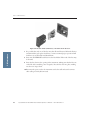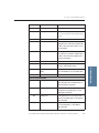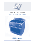
1
SpectraMax Plus384
SpectraMax 190
SpectraMax 340PC384
VersaMax
®
Microplate Spectrophotometer
Operator's Manual
Molecular Devices Corporation
1311 Orleans Drive Sunnyvale, California 94089
Part # 0112-0126 Rev A.
SpectraMax and VersaMax Plate Readers Operator’s Manual — 0112-0126 Rev A
Molecular Devices Corporation
SpectraMax® Plus384, SpectraMax 190, SpectraMax 340PC 384, and
VersaMax Operator's Manual
Copyright
© Copyright 2005, Molecular Devices Corporation. All rights reserved. No part of this
publication may be reproduced, transmitted, transcribed, stored in a retrieval system,
or translated into any language or computer language, in any form or by any means,
electronic, mechanical, magnetic, optical, chemical, manual, or otherwise, without the
prior written permission of Molecular Devices Corporation, 1311 Orleans Drive,
Sunnyvale, California, 94089, United States of America.
Patents
The SpectraMax® Plus384, SpectraMax 190, SpectraMax 340PC 384, VersaMax and
methods are protected by the following patents: U.S. Patents 4,968,148, 5,112,134,
6,151,111, and 6,188,476; Canadian Patent 1,305,334. Other U.S. and International patents pending.
Trademarks
SpectraPlate, PathCheck and Automix are trademarks and SpectraMax and SoftMax
are registered trademarks of Molecular Devices Corporation.
Apple and Macintosh are registered trademarks of Apple Computer, Incorporated.
Windows is a registered trademark of Microsoft Corporation.
All other company and product names are trademarks or registered trademarks of
their respective owners.
Disclaimer
Molecular Devices Corporation reserves the right to change its products and services
at any time to incorporate technological developments. This manual is subject to
change without notice.
Although this manual has been prepared with every precaution to ensure accuracy,
Molecular Devices Corporation assumes no liability for any errors or omissions, nor
for any damages resulting from the application or use of this information.
2
SpectraMax and VersaMax Plate Readers Operator’s Manual — 0112-0126 Rev A
Contents
Contents
1. Description . . . . . . . . . . . . . . . . . . . . . . . . . . . . . . . . . . . . . . . . . . . . . . . . . . . . . . . . . . . 1
1.1. Introduction . . . . . . . . . . . . . . . . . . . . . . . . . . . . . . . . . . . . . . . . . . . . . . . . . . . . . . . . . 1
1.2. Components . . . . . . . . . . . . . . . . . . . . . . . . . . . . . . . . . . . . . . . . . . . . . . . . . . . . . . . . . 1
1.2.1.
1.2.2.
1.2.3.
1.2.4.
1.2.5.
The Control Panel . . . . . . . . . . . . . . . . . . . . . . . . . . . . . . . . . . . . . . . . . .
The Microplate Drawer . . . . . . . . . . . . . . . . . . . . . . . . . . . . . . . . . . . . . .
Microplates . . . . . . . . . . . . . . . . . . . . . . . . . . . . . . . . . . . . . . . . . . . . . . .
The Cuvette Chamber (SpectraMax Plus384 only) . . . . . . . . . . . . . . . . . .
The Back Panel . . . . . . . . . . . . . . . . . . . . . . . . . . . . . . . . . . . . . . . . . . . .
2
3
4
5
6
2. Principles of Operation . . . . . . . . . . . . . . . . . . . . . . . . . . . . . . . . . . . . . . . . . . . . . . 9
2.1.
2.2.
2.3.
2.4.
Absorbance . . . . . . . . . . . . . . . . . . . . . . . . . . . . . . . . . . . . . . . . . . . . . . . . . . . . . . . . . . 9
Optical Density . . . . . . . . . . . . . . . . . . . . . . . . . . . . . . . . . . . . . . . . . . . . . . . . . . . . . . . 9
Transmittance. . . . . . . . . . . . . . . . . . . . . . . . . . . . . . . . . . . . . . . . . . . . . . . . . . . . . . . . 9
PathCheck™ (not VersaMax) . . . . . . . . . . . . . . . . . . . . . . . . . . . . . . . . . . . . . . . . . . . 9
2.4.1. Water Constant or Cuvette Reference Option
(SpectraMax Plus384 Only) . . . . . . . . . . . . . . . . . . . . . . . . . . . . . . . . . . .
2.4.2. Background Constant Subtraction and Blanking Considerations . . . . . . .
2.4.3. Pathcheck and Interfering Substances. . . . . . . . . . . . . . . . . . . . . . . . . . . .
2.4.4. Making Absorbance Measurements Normalized to a 1-cm Pathlength . . .
11
12
12
13
2.5. Functional Description. . . . . . . . . . . . . . . . . . . . . . . . . . . . . . . . . . . . . . . . . . . . . . . . . 14
2.5.1.
2.5.2.
2.5.3.
2.5.4.
Temperature Regulation. . . . . . . . . . . . . . . . . . . . . . . . . . . . . . . . . . . . . .
Read Types. . . . . . . . . . . . . . . . . . . . . . . . . . . . . . . . . . . . . . . . . . . . . . . .
Automix. . . . . . . . . . . . . . . . . . . . . . . . . . . . . . . . . . . . . . . . . . . . . . . . . .
Computer Control . . . . . . . . . . . . . . . . . . . . . . . . . . . . . . . . . . . . . . . . . .
14
15
16
16
3. Installation . . . . . . . . . . . . . . . . . . . . . . . . . . . . . . . . . . . . . . . . . . . . . . . . . . . . . . . . . . . 17
3.1. Unpacking . . . . . . . . . . . . . . . . . . . . . . . . . . . . . . . . . . . . . . . . . . . . . . . . . . . . . . . . . . . 17
3.2. Setting Up the Instrument . . . . . . . . . . . . . . . . . . . . . . . . . . . . . . . . . . . . . . . . . . . . . 17
4. Operation
. . . . . . . . . . . . . . . . . . . . . . . . . . . . . . . . . . . . . . . . . . . . . . . . . . . . . . . . . . . . 19
4.1. Quick Overview . . . . . . . . . . . . . . . . . . . . . . . . . . . . . . . . . . . . . . . . . . . . . . . . . . . . . . 19
4.2. Preparing for a Reading . . . . . . . . . . . . . . . . . . . . . . . . . . . . . . . . . . . . . . . . . . . . . . . . 19
4.2.1. Turn the Instrument and Computer On . . . . . . . . . . . . . . . . . . . . . . . . . 19
4.2.2. Set the Temperature (Optional) . . . . . . . . . . . . . . . . . . . . . . . . . . . . . . . . 20
SpectraMax and VersaMax Plate Readers Operator’s Manual — 0112-0126 Rev A
i
Contents
4.3. Read the Microplate. . . . . . . . . . . . . . . . . . . . . . . . . . . . . . . . . . . . . . . . . . . . . . . . . . . 20
4.4. Standalone Endpoint Cuvette Reading
(SpectraMax Plus384 Only) . . . . . . . . . . . . . . . . . . . . . . . . . . . . . . . . . . . . . . . . . . . . . 21
4.5. Standalone Endpoint Microplate Reading (SpectraMax 190 and
SpectraMax 340PC384 Only . . . . . . . . . . . . . . . . . . . . . . . . . . . . . . . . . . . . . . . . . . . . . 21
5. Maintenance . . . . . . . . . . . . . . . . . . . . . . . . . . . . . . . . . . . . . . . . . . . . . . . . . . . . . . . . . 23
5.1.
5.2.
5.3.
5.4.
5.5.
5.6.
Technical Support . . . . . . . . . . . . . . . . . . . . . . . . . . . . . . . . . . . . . . . . . . . . . . . . . . . . 23
Moving the VersaMax or SpectraMax . . . . . . . . . . . . . . . . . . . . . . . . . . . . . . . . . . . . 24
General Maintenance. . . . . . . . . . . . . . . . . . . . . . . . . . . . . . . . . . . . . . . . . . . . . . . . . . 24
Cleaning . . . . . . . . . . . . . . . . . . . . . . . . . . . . . . . . . . . . . . . . . . . . . . . . . . . . . . . . . . . . 24
Cleaning the Fan Filter. . . . . . . . . . . . . . . . . . . . . . . . . . . . . . . . . . . . . . . . . . . . . . . . . 25
Changing the Fuses . . . . . . . . . . . . . . . . . . . . . . . . . . . . . . . . . . . . . . . . . . . . . . . . . . . 25
6. Troubleshooting . . . . . . . . . . . . . . . . . . . . . . . . . . . . . . . . . . . . . . . . . . . . . . . . . . . . . 29
6.1. Error Codes and Resolutions. . . . . . . . . . . . . . . . . . . . . . . . . . . . . . . . . . . . . . . . . . . . 29
6.1.1. Error Code Classifications . . . . . . . . . . . . . . . . . . . . . . . . . . . . . . . . . . . . 29
6.2. Opening the Drawer Manually . . . . . . . . . . . . . . . . . . . . . . . . . . . . . . . . . . . . . . . . . . 34
7. Specifications . . . . . . . . . . . . . . . . . . . . . . . . . . . . . . . . . . . . . . . . . . . . . . . . . . . . . . . . 35
7.1.
7.2.
7.3.
7.4.
SpectraMax Plus384 Specifications. . . . . . . . . . . . . . . . . . . . . . . . . . . . . . . . . . . . . . . 35
SpectraMax 340PC384 Specifications . . . . . . . . . . . . . . . . . . . . . . . . . . . . . . . . . . . . . 40
SpectraMax 190 Specifications. . . . . . . . . . . . . . . . . . . . . . . . . . . . . . . . . . . . . . . . . . 44
VersaMax Specifications . . . . . . . . . . . . . . . . . . . . . . . . . . . . . . . . . . . . . . . . . . . . . . . 48
8. Appendices
. . . . . . . . . . . . . . . . . . . . . . . . . . . . . . . . . . . . . . . . . . . . . . . . . . . . . . . . . . 53
8.1. Cables . . . . . . . . . . . . . . . . . . . . . . . . . . . . . . . . . . . . . . . . . . . . . . . . . . . . . . . . . . . . . . 53
8.2. Accessories . . . . . . . . . . . . . . . . . . . . . . . . . . . . . . . . . . . . . . . . . . . . . . . . . . . . . . . . . . 54
8.3. Cuvettes in SpectraMax Plus384 . . . . . . . . . . . . . . . . . . . . . . . . . . . . . . . . . . . . . . . . . . . . . . . . . . . 54
ii
SpectraMax and VersaMax Plate Readers Operator’s Manual — 0112-0126 Rev A
1.1. Introduction
1.1.
Introduction
SpectraMax and VersaMax microplate spectrophotometers provide rapid and sensitive
measurements of a variety of analytes across a wide range of concentrations. They
measure the optical density (OD) of samples at selected wavelengths in a number of
reading modes, depending on the instrument model:
• Endpoint: at a single point in time.
• Kinetic: over a specified period of time.
• Spectral scan: over a specified wavelength range.
The VersaMax and SpectraMax 190 read 96-well microplates. The
SpectraMax 340PC384 and SpectraMax Plus384 read both 96-and 384-well
microplates.
The contents of the wells in a microplate can be mixed automatically by shaking
before each read cycle, which makes it possible to perform kinetic analysis of solidphase, enzyme-mediated reactions (mixing is not critical for liquid-phase reactions).
The temperature of the microplate chamber can be regulated, if desired from 4°C
above ambient to 45°C.
Detailed specifications of each model reader are reported in Section 7,
“Specifications”.
1.2.
Components
The main components of SpectraMax and VersaMax readers described in this manual
are:
• Control panel
• Microplate drawer
• Cuvette chamber (SpectraMax Plus384 only)
• Back panel (connections and power switch)
SpectraMax and VersaMax Plate Readers Operator’s Manual — 0112-0126 Rev A
1
1. Description
1. Description
Part 1. Description
Cuvette Chamber
Control Panel
1. Description
Back Panel
Microplate Drawer
Figure 1.1: SpectraMax Plus
1.2.1.
384
components.
The Control Panel
The control panel consists of a 2-x-20-character LCD and eleven pressure-sensitive
membrane keys that can be used to control some functions of the instrument. When
you press a control panel key, the instrument performs the associated action.
TEMP on/off
The
TEMP on/off
key enables and disables the incubator.
• When the incubator is on, the set temperature and actual temperature are shown
on the front panel LCD display.
• When the instrument is performing a kinetic or spectral scan, the temperature
keys on the front panel are disabled.
TEMP
The TEMP keys allow you to enter a set point at which to regulate the microplate
chamber temperature.
Pressing this key scrolls the temperature up or down, starting at the previous temperature setting (or the default of 37.0°C, if no setting had been made):
• Pressing the up ( ) or down ( ) arrow once increments or decrements the displayed temperature by 0.1°C.
2
SpectraMax and VersaMax Plate Readers Operator’s Manual — 0112-0126 Rev A
1.2. Components
λ (not available on VersaMax)
Selects the wavelength to be used for reading the microplate manually.
Pressing the up or down arrow key scrolls up or down through the available wavelengths, starting at the previous setting:
• Pressing the up ( ) or down ( ) arrow once increments or decrements the displayed wavelength by 1 nm.
• Pressing and holding either arrow increments or decrements the displayed wavelength by 10 nm until it is released.
96/384 (SpectraMax 340PC384 only)
Selects either 96-well or 384-well plate for a stand-alone read.
REF (SpectraMax Plus384 only)
A reading of buffer, water, or air taken in the cuvette that is used as I0 to calculate
Absorbance or % Transmittance. If no reference reading is taken, the instrument uses
the I0 values stored in the NVRAM (non-volatile memory) of the instrument.
READ CUVETTE (SpectraMax Plus384 only)
Initiates the sample reading of the cuvette.
READ (SpectraMax 340PC384 and SpectraMax 190 only)
Initiates reading of the microplate in stand-alone mode. Data is sent to the printer
port.
%T / A (SpectraMax Plus384 only)
A toggle switch used to display cuvette data as percent transmission or absorbance.
DRAWER
The
1.2.2.
DRAWER
key opens and closes the microplate drawer.
The Microplate Drawer
The microplate drawer is located on the right side of the SpectraMax and VersaMax
readers, slides in and out of the microplate chamber. A small plastic pusher, located
SpectraMax and VersaMax Plate Readers Operator’s Manual — 0112-0126 Rev A
3
1. Description
• Pressing and holding either arrow increments or decrements the displayed temperature by 1°C until it is released.
Part 1. Description
1. Description
in the front left corner of the drawer, holds the plate securely in place when the
drawer is closed.
The drawer remains in the reading chamber during read cycles.
Figure 1.2: The microplate drawer.
Microplate drawer operation varies, depending on the incubator setting:
• If the incubator is off, the drawer remains open.
• If the incubator is on, the drawer closes after approximately 10 seconds to assist in
maintaining temperature control within the microplate chamber.
Do not obstruct the movement of the drawer. If you must retrieve a plate after an
error condition or power outage and the drawer does not open, it is possible to open
it manually (see Section 6, “Troubleshooting”).
1.2.3.
Microplates
SpectraMax 190 and VersaMax readers can accommodate standard 96-well and stripwell microplates.
SpectraMax Plus384 and 340PC384 readers can accommodate standard 96-well, 384well, and strip-well microplates. When reading at wavelengths below 340 nm, special
UV-transparent, disposable or quartz microplates allowing transmission of the deep
UV spectra must be used.
Not all manufacturers' microplates are the same with regard to design, materials, or
configuration. Temperature uniformity within the microplate may vary depending on
the type of microplate used.
4
SpectraMax and VersaMax Plate Readers Operator’s Manual — 0112-0126 Rev A
1.2. Components
The Cuvette Chamber (SpectraMax Plus384 only)
1. Description
1.2.4.
Figure 1.3: The cuvette chamber.
Located at the right front of the SpectraMax Plus384, the cuvette chamber has a lid
that lifts up, allowing you to insert or remove a cuvette. The chamber contains springs
that automatically position the cuvette in the proper alignment for a reading. The
cuvette door must be closed before initiating a reading.
Cuvettes
The SpectraMax Plus384 can accommodate standard-height (45 mm), 1-cm cuvettes
and 12 x 75 mm test tubes when used with the test tube cover (Figure 1.4).
Not all manufacturers’ cuvettes are the same with regard to design, materials, or configuration. Temperature uniformity within the cuvette may vary depending on the
type of cuvette used.
Be sure to handle cuvettes on the frosted sides only. Place the cuvette into the chamber so that the “reading” (clear) sides face left and right.
The SpectraMax Plus384 does not accept the short (25 mm high) microcuvettes.
SpectraMax and VersaMax Plate Readers Operator’s Manual — 0112-0126 Rev A
5
1. Description
Part 1. Description
Figure 1.4: Test tube cover.
1.2.5.
The Back Panel
Fuse Box
Cover
Power Switch
Power Cord
Receptacle
Label
Computer
Port
Printer
Port
Figure 1.5: Schematic of the back panel of a reader.
The following components are located on the back panel of the SpectraMax and
VersaMax readers:
• Power switch: a rocker switch, labeled I/O (for on and off, respectively).
• Power cord receptacle: plug the power cord in here.
• Fuse box cover: cannot be opened while the power cord is plugged in. When
opened, it provides access to the fuse box containing two fuses that are required
for operation.
• Computer port (double-shielded 8-pin RS-232 serial, for use with an external
computer): plug one end of an 8-pin DIN serial cable into this port; the other end
attaches to the serial (modem) port of the computer.
• Printer port: (double-shielded, 25-pin parallel, for use in stand-alone operation).
Plug the 25-pin end of the cable into this port; the other end attaches to the port
on the printer.
6
SpectraMax and VersaMax Plate Readers Operator’s Manual — 0112-0126 Rev A
1.2. Components
SpectraMax and VersaMax Plate Readers Operator’s Manual — 0112-0126 Rev A
7
1. Description
• Label: provides information about the reader, such as line voltage rating, cautionary information, serial number, etc. Record the serial number shown on this label
for use when contacting Molecular Devices Technical Support.
1. Description
Part 1. Description
8
SpectraMax and VersaMax Plate Readers Operator’s Manual — 0112-0126 Rev A
2.1. Absorbance
2. Principles of Operation
2.1.
Absorbance
A = log ( I 0 ⁄ I )
where I0 is incident light, and I is transmitted light.
In this manual, we use the terms absorbance and optical density interchangeably.
2.2.
Optical Density
Optical density is the amount of light passing through a sample to a detector relative
to the total amount of light available. Optical density includes absorbance of the sample plus light scatter from turbidity.
2.3.
Transmittance
Transmittance is the ratio of transmitted light to the incident light.
T = ( I0 ⁄ I )
%T = 100T
where I0 is incident light, and I is transmitted light.
2.4.
PathCheck™ (not VersaMax)
The Beer-Lambert law states that absorbance is proportional to the distance that light
travels through the sample:
A = εbc
where A is the absorbance, ε is the molar absorbtivity of the sample, b is the pathlength and c is the concentration of the sample. In short, the longer the pathlength,
the higher the absorbance.
Microplate readers use a vertical light path so the distance of the light through the
sample depends on the volume. This variable pathlength makes it difficult to perform
extinction-based assays and also makes it confusing to compare results between
microplate readers and spectrophotometers.
The standard pathlength of a cuvette is the conventional basis for quantifying the
unique absorbtivity properties of compounds in solution. Quantitative analyses can
SpectraMax and VersaMax Plate Readers Operator’s Manual — 0112-0126 Rev A
9
2. Principles of Operation
Absorbance is the amount of light absorbed by a solution. To measure absorbance
accurately, it is necessary to eliminate light scatter. In the absence of turbidity, absorbance = optical density.
Part 2. Principles of Operation
be performed on the basis of extinction coefficients, without standard curves (e.g.
NADH-based enzyme assays). When using a cuvette, the pathlength is known and is
independent of sample volume, so absorbance is proportional to concentration.
2. Principles of Operation
In a microplate, pathlength is dependent on the liquid volume, so absorbance is proportional to both the concentration and the pathlength of the sample. Standard
curves are often used to determine analyte concentrations in vertical-beam photometry of unknowns, yet errors can still arise from pipetting the samples and standards.
The PathCheck feature automatically determines the pathlength of aqueous samples
in the microplate and normalizes the absorbance in each well to a pathlength of 1 cm.
This novel approach to correcting the microwell absorbance values is accurate to
within 2.5% of the values obtained directly in a 1-cm cuvette.
Horizontal
light path
Vertical light path
Cuvette
Microplate wells
Figure 2.1: Cuvette and microwell light paths.
Reference measurements made by reading the cuvette (Cuvette Reference, SpectraMax Plus384 only) or using factory-stored values derived from deionized water (Water
Constant) can be used to normalize the optical density data for microplate wells.
PathCheck pathlength correction is accomplished only when using the SoftMax Pro
software.
The SpectraMax Plus and SpectraMax Plus384 offer both the Cuvette Reference and
the Water Constant methods. The SpectraMax 190 and SpectraMax 340PC384 use
the Water Constant only.
The actual pathlength, d, of a solvent is found from the following equation:
Sample ( OD 1000 – OD 900 )
d ( cm ) = --------------------------------------------------------------k
10
SpectraMax and VersaMax Plate Readers Operator’s Manual — 0112-0126 Rev A
2.4. PathCheck™ (not VersaMax)
When a Cuvette Reference is used for pathlength correction, the value of k is
obtained by taking optical density measurements on the fluid in the cuvette at two
wavelengths, 1000 and 900 nm:
k = Cuvette ( OD 1000 – OD 900 )
Once the pathlength d is found, the following equation is used for the pathlength
correction:
OD Sample
OD
--------- = ----------------------cm
d ( cm )
PathCheck is applicable to almost all biological/pharmaceutical molecules in aqueous solution because they have little or no absorbance between 900 nm and
1000 nm at concentrations normally used. PathCheck can also be used with samples
containing small amounts of organics or high buffer concentrations by using the
Cuvette Reference (below).
2.4.1.
Water Constant or Cuvette Reference Option
(SpectraMax Plus384 Only)
The PathCheck measurement is based on the absorbance of water in the near infrared
region (between 900 nm and 1000 nm). If the sample is completely aqueous, has no
turbidity and has a low salt concentration (less than 0.5 M), the Water Constant is
adequate. The Water Constant is determined during manufacture and is stored in the
instrument.
If the sample contains an organic solvent such as ethanol or methanol, we recommend using the cuvette reference. It is important that the solvent does not absorb in
the 900 nm to 1000 nm range (to determine whether or not a given solvent would
interfere, see the discussion of interfering substances below). When a noninterfering
solvent is added to the aqueous sample, the water absorbance decreases proportionally
to the percentage of organic solvent present. For example, 5% ethanol decreases the
water absorbance by 5% and results in a 5% underestimation of the pathlength. You
can avoid the error by putting the same water/solvent mixture in a cuvette and using
the Cuvette Reference.
To use the Cuvette Reference, place into the cuvette port a standard 1 cm cuvette
containing the aqueous/solvent mixture that is used for the samples in the microplate.
The cuvette must be in place when you read the microplate. When you click the Read
SpectraMax and VersaMax Plate Readers Operator’s Manual — 0112-0126 Rev A
11
2. Principles of Operation
When the Water Constant is used for pathlength correction, the value of k is obtained
from the instrument. This constant is saved in the instrument in the factory and may
differ slightly from instrument to instrument.
Part 2. Principles of Operation
button in SoftMax Pro, the instrument first makes the 900 nm and 1000 nm measurements in the cuvette, and then makes the designated measurements in the microplate. The cuvette values are stored temporarily and used in the PathCheck
calculations for the microplate samples.
2. Principles of Operation
Use of Cuvette Reference with PathCheck is different from a reference reading of a
cuvette in a CuvetteSet section (by clicking the Ref button in the CuvetteSet section
tool bar in SoftMax Pro). The cuvette reference used for PathCheck calculations
(measurements at 900 nm and 1000 nm) does not produce data that can be viewed in
a CuvetteSet section and is used only with data in microplates, not cuvettes.
2.4.2.
Background Constant Subtraction and Blanking
Considerations
Raw optical density measurements of microplate samples include both pathlengthdependent components (sample and solvent) and a pathlength-independent component (OD of microplate material). The latter must be eliminated from the PathCheck calculation in order to obtain valid PathCheck-normalized results. There are
three ways to accomplish this — plate blanks, plate background constants, and
plate pre-reads — all of which are described in the PathCheck section of the SoftMax Pro manual.
2.4.3.
Pathcheck and Interfering Substances
Any material that absorbs in the 900 nm to 1000 nm spectral region could interfere
with PathCheck measurements. Fortunately, there are few materials that do interfere
at the concentrations typically used.
Turbidity is the most common interference: if you can detect any turbidity in your
sample, you should not use PathCheck. Turbidity elevates the 900 nm measurement
more than the 1000 nm measurement and causes an erroneously low estimate of
pathlength. Using a Cuvette Reference does not reliably correct for turbidity.
Samples that are highly colored in the upper visible spectrum may have absorbance
extending into the near infrared (NIR) and can interfere with PathCheck. Examples
include Lowry assays, molybdate-based assays and samples containing hemoglobins
or porphyrins. In general, if the sample is distinctly red or purple, you should check
for interference before using PathCheck.
To determine possible color interference, do the following:
• Measure the optical density at 900 nm and 1000 nm (both measured with air
reference).
• Subtract the 900 nm value from the 1000 nm value.
12
SpectraMax and VersaMax Plate Readers Operator’s Manual — 0112-0126 Rev A
2.4. PathCheck™ (not VersaMax)
• Do the same for pure water.
Organic solvents could interfere with PathCheck if they have absorbance in the
region of the NIR water peak. Solvents such ethanol and methanol do not absorb in
the NIR region, so they do not interfere, except for causing a decrease in the water
absorbance to the extent of their presence in the solution. Their passive interference
can be avoided by using the Cuvette Reference. If, however, the solvent absorbs
between 900 and 1000 nm, the interference would be similar to the interference of
highly colored samples described above. If you are considering adding an organic solvent other than ethanol or methanol, you are advised to run a spectral scan between
900 nm and 1000 nm to determine if the solvent would interfere with PathCheck.
2.4.4.
Making Absorbance Measurements Normalized to a 1-cm
Pathlength
SoftMax Pro automatically reports absorbance values normalized to a 1-cm pathlength. The table below shows results obtained with 75 µL to 300 µL yellow reagent.
Well Volume
Pathlength
Raw
Absorbance/
(µL)
(cm)
Absorbance
cm
75
0.231
0.090
100
0.300
150
SD
CV%
0.390
0.006
1.6
0.116
0.387
0.005
1.2
0.446
0.172
0.385
0.003
0.8
200
0.596
0.228
0.383
0.002
0.4
250
0.735
0.283
0.384
0.002
0.5
300
0.874
0.336
0.384
0.001
0.3
Absorbance in 1-cm cuvette = 0.386
SpectraMax and VersaMax Plate Readers Operator’s Manual — 0112-0126 Rev A
13
2. Principles of Operation
If the delta OD for the sample differs significantly from the delta OD for water, then
it is advisable not to use the PathCheck feature. Use of Cuvette Reference does not
correct for the interference with the current calculation scheme in SoftMax Pro. Currently, Cuvette Reference involves a single (automated) read at 900 nm and 1000 nm
and the automated calculations in SoftMax Pro do not compensate for color or solvent interference. However, you could correct for such interference by taking two
cuvette measurements and using a different set of calculations. For further information, contact Molecular Devices Technical Support.
Part 2. Principles of Operation
2. Principles of Operation
Optical pathlengths and raw absorbance values were directly proportional to well columns. After normalization to a 1-cm pathlength, all absorbance values, regardless of
the volume in the wells, were within 1% of the value obtained by measuring the same
solution in a 1-cm cuvette.
2.5.
Functional Description
The full power of a SpectraMax or VersaMax instrument can only be harnessed when
the instrument is controlled using SoftMax Pro software running on a computer connected to the instrument. For a complete description of the modes of operation, how
to choose instrument settings, etc., refer to the SoftMax Pro User’s Manual.
However, some functionality is available directly on the instrument without having to
use SoftMax Pro:
• Temperature control (all models)
• Wavelength control (not VersaMax)
• Fixed-point microplate readings (SpectraMax 190 and SpectraMax 340PC384)
• Fixed-point cuvette readings (SpectraMax Plus384)
2.5.1.
Temperature Regulation
SpectraMax and VersaMax instruments have been designed to regulate the temperature of the microplate chamber from 4°C above ambient to 45°C. Upon power up,
when the incubator is off, the temperature in the microplate chamber is ambient and
isothermal. Turning on the incubator by pressing the TEMP on/off key causes the
instrument to begin warming the microplate chamber. The temperature set point
defaults to 37.0°C at start-up.
Accuracy of the temperature set point is guaranteed only if the set point is at least 4°C
above ambient. If the temperature set point is lower than the ambient temperature,
the chamber temperature remains at ambient. Temperature regulation is controlled by
heaters only and, therefore, cannot cool the temperature to a setting lower than ambient. Additionally, the highest setting (45°C) can be achieved only if the ambient temperature is greater than 20°C.
Typically, the microplate chamber reaches 37.0°C in less than 30 minutes. The
microplate chamber temperature is maintained at the set point until you press the
incubator TEMP on/off key again, turning temperature regulation off.
Should you turn the incubator back on after a momentary shutdown, allow about ten
minutes for the control algorithm to fully stabilize the microplate chamber temperature.
14
SpectraMax and VersaMax Plate Readers Operator’s Manual — 0112-0126 Rev A
2.5. Functional Description
Temperature regulation and control of the microplate chamber is achieved through
electric heaters, a fan, efficient insulation, and temperature sensors. The heaters are
located in the microplate chamber, which is insulated to maintain the temperature set
point. The sensors are mounted inside the chamber and measure the air temperature.
Note: the temperature display on the SpectraMax Plus 384 control panel shows the temperature of the cuvette chamber. The microplate chamber temperature can be seen only using
SoftMax Pro.
2.5.2.
Read Types
SpectraMax and VersaMax readers can perform up to three types of read, depending
on the instrument model: endpoint, kinetic and spectrum. Instrument setup parameters for each read type are discussed in the SoftMax Pro User's Manual.
Endpoint Read
In an endpoint read, a reading of each microplate well is taken at a single or multiple
wavelengths.
Depending on the read type selected, values can be reported as optical density or
%Transmittance.
Kinetic Read
In a kinetic read the data are collected over time with multiple readings taken at regular intervals. To achieve the shortest possible interval for kinetic readings, choose
wavelengths in ascending order.
Kinetic analysis can be performed for up to 99 hours. The kinetic read interval
depends upon the instrument setup parameters chosen in SoftMax Pro.
Kinetic analysis has many advantages when determining the relative activity of an
enzyme in different types of microplate assays, including ELISAs and the purification and characterization of enzymes and enzyme conjugates. Kinetic analysis is
capable of providing improved dynamic range, precision, and sensitivity relative to
endpoint analysis.
SpectraMax and VersaMax Plate Readers Operator’s Manual — 0112-0126 Rev A
15
2. Principles of Operation
The temperature feedback closed-loop control algorithms measure the chamber air
temperature, compare it to the temperature set point, and use the difference to calculate the regulation of the heating cycles. This technique results in accurate, precise
control of the chamber temperature with a temperature variation of the air inside the
chamber of less than 1.0°C. The temperature uniformity within the microplate
depends on its design and composition.
Part 2. Principles of Operation
Spectrum Read (not VersaMax)
2. Principles of Operation
Spectral analysis measures optical density or % Transmittance across a spectrum of
wavelengths from 340 nm to 850 nm in the SpectraMax 340PC384, 190 nm to
850 nm in the SpectraMax 190, and 190 nm to 1000 nm in the SpectraMax Plus384
All spectrum readings are made using the scanning monochromators of the instrument.
2.5.3.
Automix
The Automix function permits automatic linear shaking along the long axis of the
microplate at preset intervals, thereby mixing of the contents within each well. Automix must be selected before beginning a reading. The actions associated with the
Automix setting depend on the read mode chosen:
• Endpoint mode: Automix shakes the plate for a definable number of seconds and
then reads at all selected wavelengths.
• Kinetic mode: two types of Automix can be enabled; Automix can shake the plate
for a definable number of seconds before the initial reading, and/or for a definable
number of seconds before each subsequent reading.
Use of Automix is strongly recommended for ELISAs and other solid-phase, enzymemediated reactions to enhance accuracy.
2.5.4.
Computer Control
SpectraMax and VersaMax readers are equipped with an 8-pin DIN RS-232 serial
port through which the computer communicates with the instrument. (Different
types of cables are available for connecting to different types of computers — see
Appendix 8.1., “Cables”).
SoftMax Pro software, version 4.1 or greater, is required to control SpectraMax and
VersaMax instruments.
16
SpectraMax and VersaMax Plate Readers Operator’s Manual — 0112-0126 Rev A
3.1. Unpacking
3. Installation
WARNING: Always make sure the power switch on the instrument is in the OFF
position and remove the power cord from the back of the instrument prior to any
installation or relocation of the instrument.
WARNING: Do not operate the instrument in an environment where potentially
damaging liquids or gases are present.
3.1.
Unpacking
SpectraMax and VersaMax instruments are packed in a specially designed carton.
Please retain the carton and the packing materials. If the unit should need to be
returned for repair, you must use the original packing materials and carton for shipping. If the carton has been damaged in transit, it is particularly important that you
retain it for inspection by the carrier in case there has also been damage to the
instrument.
WARNING: SpectraMax and VersaMax instruments weigh approximately 30
pounds (13.6 kg) and should be lifted with care. It is recommended that two persons
lift the instrument together, taking the proper precautions to avoid injury.
After examining the carton, place it on a flat surface in the upright position. Open the
top of the box and lift the instrument, along with the packing materials around the
ends, up and out of the shipping box. Remove the packing material from both ends
of the instrument and set the instrument down carefully. The packing list that accompanies the instrument describes all components that should have been placed in the
packing carton. Make sure all these items are present before proceeding.
3.2.
Setting Up the Instrument
1 Place the instrument on a level surface, away from direct sunlight, dust, drafts,
vibration, and moisture.
2 Turn the instrument around so that the back of the instrument is facing you.
3 Insert the serial cable into the RS-232 serial port receptacle on the back panel of the
instrument. (A Keyspan USB adapter is necessary for a Macintosh computer or a
Windows computer without a serial port; see Appendix 8.1., “Cables” for more information on adapter cables.) Attach the other end to your computer.
SpectraMax and VersaMax Plate Readers Operator’s Manual — 0112-0126 Rev A
17
3. Installation
CAUTION: Do not touch or loosen any screws or parts other than those specifically designated in the instructions. Doing so might cause misalignment and voids
the instrument warranty.
Part 3. Installation
4 Insert the female end of the power cord into the power receptacle at the rear of the
instrument. Connect the male end to a grounded power outlet of the appropriate
voltage. Molecular Devices recommends that you use a surge protector between the
power cord and the grounded power outlet.
5 If you are using a printer for reading microplates in stand-alone mode, locate the
printer port (25-pin parallel) on the rear panel. Connect one end of the cable to this
port and connect the other end to the printer. Load paper into the printer according to
the manufacturer's instructions and connect the printer's power cord.
6 Turn the instrument around so that the control panel now faces you. Ensure no cables
3. Installation
run beneath the instrument. Leave at least three inches between the back of the instrument and the nearest objects or surfaces to ensure proper ventilation and cooling.
7 For the SpectraMax Plus384, remove the tape from the cuvette door.
8 Turn on the power to the instrument, wait for the microplate drawer to open, and
remove the tape and protective covering from the drawer subplate.
18
SpectraMax and VersaMax Plate Readers Operator’s Manual — 0112-0126 Rev A
4.1. Quick Overview
4. Operation
This chapter contains operating information for SpectraMax and VersaMax Spectrophotometers.
4.1.
Quick Overview
If you are an experienced user of this instrument, the following steps provide a quick
reminder of the basic operating procedures required to perform an assay using a SpectraMax or VersaMax instrument:
1 Turn on the power switch (located on the back panel). The microplate drawer opens
automatically.
(incubator) key to turn the incubator on and bring the chamber to the default temperature of 37.0°C. The microplate drawer closes.
3 If the incubator is on, the LCD shows the current temperature along with the tem-
perature set point. To change the set point (to any setting from ambient +4° to 45°C),
press the up or down arrow keys.
4 Select the desired instrument settings (read mode, type of analysis, template, etc.)
using SoftMax Pro software on the external computer.
5 If you are performing kinetic analysis, add substrate at this time.
6 Load the prepared microplate into the drawer, being sure to match well A1 with the
upper left-hand corner of the drawer.
7 Using SoftMax Pro, start the reading.
4.2.
Preparing for a Reading
4.2.1.
Turn the Instrument and Computer On
The power switch is located on the back panel. Press the rocker switch to the ON
position.
The instrument automatically performs diagnostic checks to ensure that it is functioning correctly. Turn the computer on at this time also and start the SoftMax Pro
software program.
SpectraMax and VersaMax Plate Readers Operator’s Manual — 0112-0126 Rev A
19
4. Operation
2 If you want to regulate the temperature inside the chamber, touch the TEMP on/off
Part 4. Operation
4.2.2.
Set the Temperature (Optional)
To set the temperature within the microplate chamber, you should turn on the incubator first, allowing enough time for the temperature to reach the set point before
performing a reading. When you first turn the instrument on, up to 60 minutes may
be required for the temperature within the chamber to reach the set point. Turning on
the incubator and choosing a temperature set point can be done using the software or
the front panel of the instrument (described here).
Temperature cannot be regulated at a set point that is lower than 4°C above the
ambient temperature.
To enable the incubator:
• Press the incubator
TEMP on/off
key.
4. Operation
• The LCD display indicates that temperature control is on and shows the set point
and current temperature of the microplate chamber.
To change the temperature set point:
• Press the up or down arrow keys until the desired temperature set point is shown
in the display.
The microplate chamber temperature is maintained at the set point until you disable
temperature control by touching the incubator key again. When the incubator is off,
the temperature within the microplate chamber gradually returns to ambient.
Should you turn the incubator back on after a momentary shutdown, allow about ten
minutes for the control algorithm to fully stabilize the microplate chamber temperature.
4.3.
Read the Microplate
BIOHAZARD: The underside of the microplate must be dry prior to placing it in
the drawer. If the microplate has fluid on the underside, dry it using a paper towel (or
equivalent) before placing it in the drawer.
• Insert the filled microplate into the drawer, matching well A1 with the upper
left hand position of the drawer. Make sure the microplate is flat against the
drawer bottom.
• You must have SoftMax Pro software running on a computer connected to the
instrument. Press the READ button in SoftMax Pro to start the plate read.
• When reading is complete, the drawer of the instrument opens, allowing you to
remove the microplate. If the incubator is on, the drawer closes again after approximately 10 seconds.
20
SpectraMax and VersaMax Plate Readers Operator’s Manual — 0112-0126 Rev A
4.4. Standalone Endpoint Cuvette Reading (SpectraMax Plus 384 Only)
• If you return to the instrument and find the drawer closed after a reading has
finished, press the DRAWER key. When the drawer opens, you can remove the
microplate.
For more information about plate reading, please consult the SoftMax Pro User's
Manual.
4.4.
Standalone Endpoint Cuvette Reading
(SpectraMax Plus384 Only)
When operating the SpectraMax Plus384 as a stand-alone system, you can obtain a
fixed-wavelength reading of the cuvette:
• Choose the wavelength by pressing the up or down arrows beneath the display
labeled λ.
To read the cuvette:
• Press the
REF
key for a reference reading.
• Press the
READ CUVETTE
key for a sample reading.
The resulting data can be displayed as absorbance or percent transmission by toggling
the %T/A key.
The data is sent to the printer port of the instrument. A new cuvette can be loaded
into the SpectraMax Plus384 while the results from the first reading are being printed.
Note: due to the continuous changes in printer technology leading to printer obsolescence, and the ability of SoftMax Pro software to print on PC-compatible and Macintosh-compatible printers, Molecular Devices does not recommend relying on printing
in standalone mode.
Keep the cuvette door closed when reading a cuvette.
See Appendix 8.3., “Cuvettes in SpectraMax Plus384” for cuvette types that have
been tested with the SpectraMax Plus384.
4.5.
Standalone Endpoint Microplate Reading (SpectraMax 190 and
SpectraMax 340PC384 Only
When operating the SpectraMax 190 and SpectraMax 340PC384 as stand-alone systems, you can obtain a fixed-wavelength reading of the microplate:
SpectraMax and VersaMax Plate Readers Operator’s Manual — 0112-0126 Rev A
21
4. Operation
• Set the temperature of the cuvette/microplate chamber using the keys on the left
side of the control panel.
Part 4. Operation
• Choose the wavelength by pressing the up or down arrows beneath the display
labeled λ.
• Set the temperature of the microplate chamber using the keys on the left side of
the control panel.
To read the microplate:
• Press the
READ
key.
The resulting data is sent to the printer port of the instrument.
4. Operation
Note: due to the continuous changes in printer technology leading to printer obsolescence, and the ability of SoftMax Pro software to print on PC-compatible and Macintosh-compatible printers, Molecular Devices does not recommend relying on printing
in standalone mode.
22
SpectraMax and VersaMax Plate Readers Operator’s Manual — 0112-0126 Rev A
5.1. Technical Support
5. Maintenance
5.1.
Technical Support
Molecular Devices Corporation is a leading worldwide manufacturer and distributor
of analytical instrumentation. We are committed to the quality of our products and
to fully supporting our customers with the highest possible level of technical service.
In order to fully benefit from our technical services, please complete the registration
card and return it to the address printed on the card.
If you have any problems using your SpectraMax or VersaMax reader, in the U.S.,
contact our Technical Services group at 1-800-635-5577; elsewhere contact your
local representative.
WARNING: All maintenance procedures described in this manual can be safely
performed by qualified personnel. Maintenance not covered in this manual should be
performed only by a Molecular Devices representative.
WARNING: Removal of protective covers that are marked with the High Voltage
warning symbol shown below can result in a safety hazard.
WARNING: Always turn the power switch off and disconnect the power cord from
the main power source before performing any maintenance procedure that requires
removal of any panel or cover or disassembly of any interior instrument component.
WARNING: Never perform any operation on the instrument in an environment
where liquids or potentially damaging gases are present.
WARNING: Risk of electrical shock. Refer servicing to qualified personnel.
CAUTION: Use of organic solvents (such as dichloromethane) may cause harm to
the optics in the instrument. Extreme caution is advised when using organic solvents.
Always use a plate lid and avoid placing a plate containing these materials in the reading chamber for prolonged periods of time. Damage caused by the use of incompatible or aggressive solvents is NOT covered by the instrument warranty.
SpectraMax and VersaMax Plate Readers Operator’s Manual — 0112-0126 Rev A
23
5. Maintenance
BIOHAZARD: It is your responsibility to decontaminate the instrument, as well as
any accessories, before requesting service by Molecular Devices representatives and
before returning the instrument or any components to Molecular Devices Corporation.
Part 5. Maintenance
CAUTION: Never touch any of the optic mirrors, filters, or cables or their housing,
or manifold. The optics are extremely delicate, and critical to use of the instrument.
CAUTION: Do not touch or loosen any screws or parts other than those specifically designated in the instructions. Doing so could cause misalignment and possibly
void the warranty.
5.2.
Moving the VersaMax or SpectraMax
If you need to relocate a VersaMax or SpectraMax, follow these steps.
WARNING: SpectraMax and VersaMax instruments weigh approximately
35 pounds (16 kilograms). To avoid injury, it is recommended that two people lift the
instrument together, using proper lifting techniques.
1 Remove any microplate from the drawer and then close the drawer.
2 Turn off the power switch and unplug the power cord from the source and from the
5. Maintenance
receptacle on the back of the instrument.
3 Depending on the distance that you are moving the instrument, you may want to
repackage the instrument in its original shipping carton. Otherwise, carry the instrument or place it on a rolling cart to transport it.
4 Ensure that the new location meets the proper specifications as described in Section
3.2., “Setting Up the Instrument”.
5.3.
General Maintenance
Keep the drawer closed when the instrument is not in use. The drawer can be opened
by pressing the DRAWER button. Always close the drawer immediately prior to
switching the instrument off.
5.4.
Cleaning
BIOHAZARD: Wear gloves during any cleaning procedure that could involve contact with either hazardous or biohazardous materials or fluids.
WARNING: Never clean the inside of the instrument.
Periodically, you should clean the outside surfaces of the instrument using a cloth or
sponge that has been dampened with water:
• Do not use abrasive cleaners.
• If required, clean the surfaces using a mild soap solution diluted with water or a
glass cleaner and then wipe with a damp cloth or sponge to remove any residue.
24
SpectraMax and VersaMax Plate Readers Operator’s Manual — 0112-0126 Rev A
5.5. Cleaning the Fan Filter
• Do not spray cleaner directly onto the instrument.
If needed, clean the microplate drawer using a cloth or sponge that has been dampened with water.
Should fluids spill in the drawer area (when the drawer is out), they are directed to a
tray at the bottom of the instrument, from which they exit to the bench or counter
beneath the instrument. Wipe up any spills immediately.
Do not allow excess water or other fluids to drip inside the instrument.
5.5.
Cleaning the Fan Filter
The fan filter on the bottom of the instrument requires periodic cleaning. The frequency of cleaning depends on how dusty your particular lab is and could range from
once a month to once every six months.
1 Turn power to the instrument OFF and then remove the power cord and cables from
the back of the instrument.
so that it rests flat on the bench.
3 Pop the black fan cover off and remove the filter.
4 Clean the filter by blowing clean, canned air through it or by rinsing it — first with
water and then with alcohol — and allowing it to dry completely.
5 Place the clean, dry filter over the fan and replace the black cover.
6 Turn the instrument back over. Reconnect the power cord and cables to the instrument.
5.6.
Changing the Fuses
Fuses burn out occasionally and must be replaced.
If the instrument does not seem to be getting power after switching it on (the LCD
shows no display):
• Check to see whether the power cord is securely plugged in to a functioning
power outlet and to the receptacle at the rear of the SpectraMax or VersaMax.
If power failed while the instrument was already on:
• Check that the power cord is not loose or disconnected and that power to the
power outlet is functioning properly.
If these checks fail to remedy the loss of power, follow the steps listed below to replace
the fuses. Spare fuses (two U.S. and two metric) are shipped with the instrument. The
SpectraMax and VersaMax Plate Readers Operator’s Manual — 0112-0126 Rev A
25
5. Maintenance
2 Remove any plate or adapter from the instrument drawer. Turn the instrument over
Part 5. Maintenance
U.S. and metric fuses are identical except for physical size. They may be taped to the
back of the instrument.
If you no longer have spare fuses, you may obtain new ones from Molecular Devices
(part numbers: 4601-0013 for U.S., 4601-0014 for metric) or from a local hardware
store. Make sure fuses are rated SLOWBLOW (U.S.: 4-amp time-delay; metric: 4amp, 5 x 20 mm, time-delay).
To change fuses:
1 Switch power to the instrument off and then remove the power cord from the outlet
and from the instrument power cord receptacle.
2 Remove the printer cable and computer cable (if connected) from the back of the
instrument.
3 Turn the instrument around for easy access to the rear panel.
4 On the left-hand side of the rear panel (viewed from the back) is the power switch,
5. Maintenance
fuse box, and power cord receptacle. As shown in the figures below, press to the left of
the black plastic cover of the fuse box to release it. Pull the fuse box cover away from
the instrument. The fuse box will begin to slide forward.
Power
Receptacle
Fuse Box
Power
Switch
Figure 5.1: Power receptacle, fuse box, and power switch.
5 Continue gently pulling the fuse box forward until it is free of the instrument.
26
SpectraMax and VersaMax Plate Readers Operator’s Manual — 0112-0126 Rev A
5.6. Changing the Fuses
Figure 5.2: Removing the fuse box.
6 When removed, the fuse assembly will appear as shown in Figure 5.3. The holder
inside contains two fuses.
5. Maintenance
Figure 5.3: The fuse box and holder (with fuses), removed from instrument.
SpectraMax and VersaMax Plate Readers Operator’s Manual — 0112-0126 Rev A
27
Part 5. Maintenance
Figure 5.4: The fuse holder (with fuses), removed from the fuse box.
7 It is possible that only one of the fuses may have blown. However, Molecular Devices
5. Maintenance
recommends that you replace both fuses to ensure continued proper operation. Pull
both fuses out of the holder and discard them.
8 Insert new SLOWBLOW-rated fuses into the fuse holder. Either end of the fuse may
be forward.
9 Insert the fuse box into the opening in the instrument, making sure that the fuses are
on the left side (toward the power receptacle). Press the fuse box into place, making
sure the cover snaps closed.
10 Reconnect the power cord to the instrument and to the wall outlet and reconnect
other cables previously disconnected.
28
SpectraMax and VersaMax Plate Readers Operator’s Manual — 0112-0126 Rev A
6.1. Error Codes and Resolutions
6. Troubleshooting
This chapter lists error codes that may occur while using the instrument, followed by
their most likely causes and remedies.
Maintenance procedures are described in Chapter 5.
For problems with the SpectraMax or VersaMax that are not listed here, in the U.S.,
contact Molecular Devices Technical Services group at 1-800-635-5577; elsewhere,
call your local representative.
BIOHAZARD: It is your responsibility to decontaminate the instrument, as well as
any accessories, before requesting service by Molecular Devices representatives and
before returning the instrument or any components to Molecular Devices Corporation.
6.1.
Error Codes and Resolutions
The LCD displays Fatal Error codes when a situation arises that requires attention.
Any reading in progress will stop.
For assistance regarding warning messages, contact your local Molecular Devices representative.
6.1.1.
Error Code Classifications
Not all error messages are listed in this manual. The errors are grouped in relationship
to possible causes as follows:
SpectraMax and VersaMax Plate Readers Operator’s Manual — 0112-0126 Rev A
29
6. Troubleshooting
Warning messages do not stop a reading but are logged in the error buffer. Warning
messages indicate a situation that requires attention but is not sufficient to stop or
prevent a reading. Examples of situations that might cause warning messages are low
memory, entries being out of range, or operations that could result in loss of data.
These messages are generally self-explanatory.
Part 6. Troubleshooting
Table 6.1: SpectraMax and VersaMax error code ranges.
ERROR CODE NUMBERS
100–199
POSSIBLE CAUSES
Errors possibly caused by unrecognized commands being
sent from the computer to the instrument.
200–299
Errors probably due to a main board failure or an error in
the firmware code. Most of these errors require the assistance of Technical Support.
300–399
Instrument errors due to either a main board failure or
other system failure. Most of these errors require the assistance of Technical Support.
400–499
Errors caused by a motor motion failure. Most of these
errors require the assistance of Technical Support.
500–599
Errors due to failure or improper initialization of the instruments non-volatile memory (NVRAM). All of these errors
require the assistance of Technical Support.
6. Troubleshooting
Some errors (shown in boldface in the following table) are considered fatal in that if
they are detected during power up, the instrument aborts the power up sequence and
displays “FATAL ERROR” on the LCD panel.
Check the following list to see if there is something that you can do to change the
condition of the instrument to prevent the fatal error. (e.g., closing the cuvette door
during the power up sequence prevents errors 111, 219, 302, and 310).
After correcting the problem, leave the instrument on for about five minutes, turn it
off and then back on.
If you continue to get the fatal error message on power up, record the error message
number and contact Molecular Devices Technical Support or your local representative for assistance.
If the instrument is functioning normally when using SoftMax Pro, no errors should
be in the buffer (except error number 100).
30
SpectraMax and VersaMax Plate Readers Operator’s Manual — 0112-0126 Rev A
6.1. Error Codes and Resolutions
Table 6.2: Error codes, error messages, and notes about the errors.
ERROR CODE
ERROR MESSAGE
NOTES
100–199: UNRECOGNIZED COMMAND ERRORS SENT FROM THE COMPUTER
100
command not found
Command string not recognized.
101
invalid argument
Command argument not recognized.
102
too many arguments
Too many arguments after command.
103
not enough arguments
Missing arguments.
104
input line too long
Too many characters in the input line.
105
command invalid,
Instrument could not perform the give
system busy
command because it was busy doing
another task.
106
107
command invalid, mea-
Instrument could not perform command
surement in progress
because a measurement was in progress.
no data to transfer
Inputting transfer when there's no data in
the buffer.
data buffer full
Too many data sets in the buffer. Can be
caused by setting up a long kinetic and
disconnecting computer or SoftMax Pro is
preempted by another application.
109
error buffer overflow
More than 65 errors in the buffer, clear the
buffer.
110
stray light cuvette, door
Cuvette door open while doing a read.
open?
111
invalid read settings
200–299: FIRMWARE ERRORS
200
assert failed
Firmware error.
201
bad error number
Firmware error.
202
receive queue overflow
Caused by external device sending too
much data over serial port and ignoring
flow control.
SpectraMax and VersaMax Plate Readers Operator’s Manual — 0112-0126 Rev A
31
6. Troubleshooting
108
Part 6. Troubleshooting
ERROR CODE
203
ERROR MESSAGE
NOTES
serial port parity error
Parity bit error detected with incoming
serial data.
204
serial port overrun error
Caused by host computer sending too much
data and ignoring the flow control signal.
205
serial port framing error
206
cmd generated too much
Firmware error.
output
207
fatal trap
Instrument error. Instrument locks up.
208
RTOS error
Firmware error.
209
stack overflow
Firmware error.
210
unknown interrupt
Firmware error.
300–399: HARDWARE ERRORS
300
thermistor faulty
Unable to read a reasonable thermistor
value. Thermistor faulty or disconnected,
6. Troubleshooting
Main board problem, or ambient temperature out of range.
301
safe temperature limit
A temperature of over 50°C detected on
exceeded
one or more of the 4 thermistors. Temperature will be shut off and remain off until a
successful completion of power-up reset.
302
low light
Not enough light detected to make an
accurate measurement. If doing a cuvette
read, the cuvette door may be open.
303
unable to cal dark current
Too much stray light detected on powerup, faulty or disconnected pre-amp boards.
304
signal level saturation
During a cuvette read, could be due to
cuvette door being open.
305
reference level saturation
During a cuvette read, could be due to
cuvette door being open.
306
plate air cal fail, low light
Minimum signal/reference ratio not met
during air calibration.
32
SpectraMax and VersaMax Plate Readers Operator’s Manual — 0112-0126 Rev A
6.1. Error Codes and Resolutions
ERROR CODE
ERROR MESSAGE
307
cuv air ref fail
308
stray light
NOTES
Light leak in reading chamber or cuvette
door open. Could also be a faulty pre-amp
board.
309
front panel not responding
LCD front panel bad or disconnected.
312
gain calibration failed
Power-up calibration and check of signal
path gain is out of tolerance. Could be due
to bad or disconnected pre-amp or excessive stray light.
313
reference gain check fail
Power-up check of the Reference amplifier's gain out of tolerance. Could be due
to bad or disconnected pre-amp board or
excessive stray light.
314
low lamp level warning
315
can't find zero order
On power-up, grating motor could not
find zero-order home position.
317
grating motor driver
Grating motor didn't move to where it
faulty
was commanded to in a reasonable time.
monitor ADC faulty
400–499: MOTION ERRORS
400
carriage motion error
Carriage did not move to either of its
photo interrupts in a reasonable time, or
can't find its photo interrupt.
401
filter wheel error
Filter wheel did not move to its photo
interrupt in a reasonable time, or can't
find its photo interrupt.
402
grating error
Grating did not move to its photo interrupt in a reasonable time, or can't find its
photo interrupt.
403
stage error
Stage did not move to its photo interrupt
in a reasonable time, or can't find its
photo interrupt.
SpectraMax and VersaMax Plate Readers Operator’s Manual — 0112-0126 Rev A
33
6. Troubleshooting
316
Part 6. Troubleshooting
ERROR CODE
ERROR MESSAGE
NOTES
500–599: NVRAM ERRORS
500
NVRAM CRC corrupt
The CRC for the NVRAM data is corrupt.
501
NVRAM Grating cal data
Grating calibration data is unreasonable.
bad
502
NVRAM Cuvette air cal
Cuvette air calibration data is unreasonable.
data error
503
NVRAM Plate air cal data
Plate air calibration data is unreasonable.
error
504
NVRAM Carriage offset
Carriage offset data is unreasonable.
error
505
NVRAM Stage offset error
Stage offset data is unreasonable.
506
NVRAM Battery
Time to replace the NVRAM battery (U3).
6. Troubleshooting
For all other error messages (codes not listed here), please contact your local Molecular Devices representative for assistance.
6.2.
Opening the Drawer Manually
• If an error occurs while the drawer is closed and you need to remove a microplate,
press the DRAWER key.
• If the drawer does not open, turn power to the instrument off and then on again.
• If the drawer remains closed, turn the incubator off (if it was on) by pressing the
TEMP on/off key.
• If the drawer still remains closed, try using a blunt, flat object (such as a spatula)
to open the door. With your index finger, pull the microplate drawer out of the
instrument (do not force the drawer) and remove the microplate. This action will
not harm the instrument, but should only be taken if the first two options have
failed to open the drawer.
If you are still unable to open the drawer, contact your local Molecular Devices
representative.
34
SpectraMax and VersaMax Plate Readers Operator’s Manual — 0112-0126 Rev A
7.1. SpectraMax Plus384 Specifications
7. Specifications
7.1.
SpectraMax Plus384 Specifications
Thermal specifications for microplates used in the SpectraMax Plus384 apply to flatbottom microplates with isolated wells.
All other microplate specifications apply to standard 96-well polystyrene flat-bottom
microplates.
Performance specifications for cuvette readings apply only to aqueous solutions having solute molal concentrations less than 0.4 M.
When pathlength compensation is applied to microplate absorbance measurements,
agreement with cuvette absorbance measurements for the same solution requires that
the solution volume in the microplate well is between 100 µL and 300 µL.
Technical specifications are subject to change without notice.
PHOTOMETRIC PERFORMANCE
Wavelength range
Wavelength selection
190–1000 nm
Monochromator tunable in 1-nm increments
Wavelength bandwidth
≤ 2.0 nm full width half maximum
Wavelength accuracy
± 1.0 nm across wavelength range
Photometric range
Photometric resolution
± 0.2 nm
0 to 4.000 OD
0.001 OD
Photometric accuracy/linearity
(microplate), 0–2.0 OD
190–1000 nm < ± 1.0% and ± 0.006 OD
Photometric accuracy/linearity
(cuvette), 0–2.0 OD
190–1000 nm < ± 1.0% and ± 0.005 OD
Photometric precision (repeatability),
0–2.0 OD
190–1000 nm < ± 1.0% and ± 0.003 OD
Stray light
Photometric stabilization
7. Specifications
Wavelength repeatability
≤ 0.05% at 230 nm
Instantaneous
SpectraMax and VersaMax Plate Readers Operator’s Manual — 0112-0126 Rev A
35
Part 7. Specifications
Photometric drift
None — continuous referencing of
monochromatic input
Calibration
Automatic before first kinetic read and
before every endpoint reading
Optical alignment
Light source
Average lamp lifetime
Illumination
None required
Xenon flash lamp (5 Watts)
1 billion flashes
Top down (microplates); horizontal
(cuvettes)
Photodetectors
Silicon photodiode
PHOTOMETRIC ANALYSIS MODES
Standalone
• Single wavelength Absorbance or
%Transmittance reading of the cuvette
(or test tube)
Using SoftMax Pro
• Express data as Absorbance or
%Transmittance
• Single wavelength reading of microplate and/or cuvette
• Multiple wavelength (up to six) reading
7. Specifications
of microplate or cuvette
• Kinetic and kinetic graphics of microplate and/or cuvette
• Spectral scan (190–1000 nm) of microplate and/or cuvette
36
SpectraMax and VersaMax Plate Readers Operator’s Manual — 0112-0126 Rev A
7.1. SpectraMax Plus384 Specifications
MEASUREMENT TIME (CALIBRATION OFF)
Microplate read time (endpoint) —
standard read*
• 96 wells in 9 seconds
(single wavelength)
• 96 wells in 19 seconds
*Measurement conditions: endpoint, column
priority (for dual-wavelength measurements),
(dual wavelength, 425 & 650 nm)
• 384 wells in 29 seconds
(single wavelength)
calibrate off.
• 384 wells in 59 seconds
(dual wavelength, 425 & 650 nm)
Microplate read time (endpoint) —
speed read*
• 96 wells in 5 seconds
(single wavelength)
• 96 wells in 12 seconds
*Measurement conditions: endpoint, column
priority (for dual-wavelength measurements),
(dual wavelength, 425 & 650 nm)
• 384 wells in 16 seconds
(single wavelength)
calibrate off.
• 384 wells in 34 seconds
(dual wavelength, 425 & 650 nm)
Microplate kinetic read intervals
• 96 wells, 9-second minimum interval
between readings (single wavelength)
• 1 column, 2-second minimum interval
between readings (single wavelength)
between readings (single wavelength)
Cuvette read time (endpoint)
• 1 second (single wavelength)
Cuvette kinetic read intervals
• 2-second minimum interval between
readings (single wavelength)
SCAN SPEED
Cuvette: normal scan
Cuvette: speed scan
Microplate: normal scan
45*K nm/min (K = wavelength interval)
130*K nm/min
33*K nm/min (8-well strip);
21*K nm/min (16-well strip)
Microplate: speed scan
135*K nm/min (8-well strip);
77*K nm/min (16-well strip)
SpectraMax and VersaMax Plate Readers Operator’s Manual — 0112-0126 Rev A
37
7. Specifications
• 384 wells, 29-second minimum interval
Part 7. Specifications
TEMPERATURE REGULATION
Reading chamber
Isothermal when temperature regulation is
not enabled
Range
4°C above ambient to 45°C when temperature regulation enabled. The ambient temperature must be >20°C to achieve
temperature regulation at 45°C.
Resolution
Accuracy
Temperature uniformity at equilibrium
Chamber warm-up time
± 0.1°C
± 1.0°C for microplate and cuvette chamber
± 0.5°C at 37°C
15–30 minutes (measured on air) after
initiation of temperature regulation
Temperature regulation
Drift
Temperature regulation diagnostics
4 sensors
± 0.2°C (regulated)
Temperature regulation system is continuously monitored and updated
Evaporation
Plate lid required to minimize evaporative
cooling
Recommended microplate
Flat-bottom microplates with isolated wells
7. Specifications
and lid
AUTOMIX WITH SOFTMAX PRO
Plate mixing modes
Selectable: off, once prior to any reading, and
once prior to and between kinetic readings
Plate mixing duration
Selectable: 1 to 999 seconds
(three-second default)
38
SpectraMax and VersaMax Plate Readers Operator’s Manual — 0112-0126 Rev A
7.1. SpectraMax Plus384 Specifications
COMPATIBILITY
Microplates
Standard and half-area 96-well flat-bottomed microplates (0.3 mL). 384-well flatbottomed microplates. Polystyrene plates
for wavelengths above 340 nm; UV transparent plates above 220 nm; quartz plates
above 190 nm.
Cuvettes
Standard height (45 mm) cells with 10 mm
pathlength (12.5 mm x 12.5 mm outside)
with minimum inside width of 4 mm (typical
for 3 mL volume cells). See Section 8.3.,
“Cuvettes in SpectraMax Plus384” for more
information.
Test tubes
12 x 75 mm test tubes can be used in the
cuvette chamber with the test tube cover.
GENERAL INSTRUMENT
Display
Operating panel
Self-diagnosis
Spill control
2-x-20-character backlit LCD
8-key membrane keypad
Continuous on-board diagnostics
Drawer mechanism and reading chamber
7. Specifications
assembly protected from accidental
spillage by drainage ports
Computer interface
8-pin DIN RS-232 serial
(double shielding required)
Printer interface
Parallel 25-pin to Centronics
(double shielding required)
Microplates supported
All 96-well and strip-well microplates,
including lids
SpectraMax and VersaMax Plate Readers Operator’s Manual — 0112-0126 Rev A
39
Part 7. Specifications
ENVIRONMENTAL
Operating temperature
Operating humidity
Storage temperature
15°C to 40°C
0 to 70%, non-condensing
-20°C to 65°C
PHYSICAL
Size (h x w x d)
8.6" (220 mm) x 22.8" (580 mm)
x 15" (380 mm)
Weight
Power consumption
Line voltage and frequency
7.2.
30 lb (13.6 kg)
< 250 W
90–250 VAC autoranging, 50/60 Hz
SpectraMax 340PC384 Specifications
Thermal specifications for microplates used in the SpectraMax 340PC384 apply to
flat-bottom microplates with isolated wells.
All other microplate specifications apply to standard 96-well polystyrene flat-bottom
microplates.
7. Specifications
Technical specifications are subject to change without notice.
PHOTOMETRIC PERFORMANCE
Wavelength range
Wavelength selection
Monochromator tunable in 1-nm increments
Wavelength bandwidth
≤ 2.0 nm full width half maximum
Wavelength accuracy
± 1.0 nm across wavelength range
Wavelength repeatability
Photometric range
Photometric resolution
Photometric accuracy/linearity
(microplate), 0–2.0 OD
40
340–850 nm
± 0.2 nm across all optical channels
0 to 4.000 OD
0.001 OD
340–850 nm < ± 1.0% and ± 0.006 OD
SpectraMax and VersaMax Plate Readers Operator’s Manual — 0112-0126 Rev A
7.2. SpectraMax 340PC384 Specifications
Photometric precision (repeatability),
0–2.0 OD
Stray light
Photometric stabilization
Photometric drift
340–850 nm < ± 1.0% and ± 0.003 OD
≤ 0.05% at 340 nm
Instantaneous
None — continuous referencing of
monochromatic input
Calibration
Automatic before first kinetic read and
before every endpoint reading
Optical alignment
Light source
Average lamp lifetime
Illumination
Photodetectors
None required
Xenon flash lamp (5 Watts)
1 billion flashes
Top down
Silicon photodiode
PHOTOMETRIC ANALYSIS MODES
Standalone
• Single wavelength Absorbance reading of the microplate
Using SoftMax Pro
• Express data as Absorbance or
%Transmittance
• Single wavelength reading of microplate
of microplate
• Kinetic and kinetic graphics of microplate
• Spectral scan (340–850 nm) of microplate
SpectraMax and VersaMax Plate Readers Operator’s Manual — 0112-0126 Rev A
41
7. Specifications
• Multiple wavelength (up to six) reading
Part 7. Specifications
MEASUREMENT TIME (CALIBRATION OFF)
Read time (endpoint) — standard read
• 96 wells in 9 seconds
(single wavelength)
• 96 wells in 19 seconds
(dual wavelength, 425 & 650 nm)
• 384 wells in 29 seconds
(single wavelength)
• 384 wells in 59 seconds
(dual wavelength, 425 & 650 nm)
Kinetic read intervals
• 96 wells, 9-second minimum interval
between readings (single wavelength)
• 1 column, 2-second minimum interval
between readings (single wavelength)
• 384 wells, 29-second minimum interval
between readings (single wavelength)
SCAN SPEED
Microplate: normal scan
33*K nm/min (8-well strip);
21*K nm/min (16-well strip)
Microplate: speed scan
135*K nm/min (8-well strip);
77*K nm/min (16-well strip)
7. Specifications
TEMPERATURE REGULATION
Reading chamber
Isothermal when temperature regulation is
not enabled
Range
4°C above ambient to 45°C when temperature regulation enabled. The ambient temperature must be >20°C to achieve
temperature regulation at 45°C.
Resolution
Accuracy
Temperature uniformity at equilibrium
Chamber warm-up time
± 0.1°C
± 1.0°C for microplate and cuvette chamber
± 0.5°C at 37°C
15–30 minutes (measured on air) after
initiation of temperature regulation
42
SpectraMax and VersaMax Plate Readers Operator’s Manual — 0112-0126 Rev A
7.2. SpectraMax 340PC384 Specifications
Temperature regulation
Drift
Temperature regulation diagnostics
4 sensors
± 0.2°C (regulated)
Temperature regulation system is continuously monitored and updated
Evaporation
Plate lid required to minimize evaporative
cooling
Recommended microplate
Flat-bottom microplates with isolated wells
and lid
AUTOMIX WITH SOFTMAX PRO
Plate mixing modes
Selectable: off, once prior to any reading, and
once prior to and between kinetic readings
Plate mixing duration
Selectable: 1 to 999 seconds (3-second default)
Microplates
Standard and half-area 96-well flat-bottomed
COMPATIBILITY
microplates (0.3 mL). 384-well flat-bottomed
microplates. Polystyrene plates for wavelengths above 340 nm; UV transparent plates
above 220 nm; quartz plates above 190 nm.
GENERAL INSTRUMENT
Operating panel
Self-diagnosis
Spill control
7. Specifications
Display
2-x-20-character backlit LCD
8-key membrane keypad
Continuous on-board diagnostics
Drawer mechanism and reading chamber
assembly protected from accidental
spillage by drainage ports
Computer interface
8-pin DIN RS-232 serial
(double shielding required)
Printer interface
Parallel 25-pin to Centronics
(double shielding required)
Microplates supported
All 96-well and strip-well microplates,
including lids
SpectraMax and VersaMax Plate Readers Operator’s Manual — 0112-0126 Rev A
43
Part 7. Specifications
ENVIRONMENTAL (FOR INDOOR USE ONLY)
Operating temperature
Operating altitude
5°C to 40°C
< 2000 m
Installation category
II
Pollution degree
2
Operating humidity
Storage temperature
< 80%
-20°C to 65°C
PHYSICAL
Size (h x w x d)
Weight
Power consumption
Line voltage and frequency
7.3.
8.6" (220 mm) x 22.8" (580 mm) x 15" (380 mm)
30 lb (13.6 kg)
< 250 W
90–250 VAC autoranging, 50/60 Hz
SpectraMax 190 Specifications
Thermal specifications for microplates used in the SpectraMax 190 apply to flat-bottom microplates with isolated wells.
7. Specifications
All other microplate specifications apply to standard 96-well polystyrene flat-bottom
microplates.
Technical specifications are subject to change without notice.
PHOTOMETRIC PERFORMANCE
Wavelength range
Wavelength selection
Monochromator tunable in 1-nm increments
Wavelength bandwidth
≤ 2.0 nm full width half maximum
Wavelength accuracy
± 1.0 nm across wavelength range
Wavelength repeatability
Photometric range
44
190–850 nm
± 0.2 nm across all optical channels
0 to 4.000 OD
SpectraMax and VersaMax Plate Readers Operator’s Manual — 0112-0126 Rev A
7.3. SpectraMax 190 Specifications
Photometric resolution
0.001 OD
Photometric accuracy/linearity
(microplate), 0–2.0 OD
190–850 nm < ± 1.0% and ± 0.006 OD
Photometric precision (repeatability),
0–2.0 OD
190–850 nm < ± 1.0% and ± 0.003 OD
Stray light
Photometric stabilization
Photometric drift
≤ 0.05% at 340 nm
Instantaneous
None — continuous referencing of
monochromatic input
Calibration
Automatic before first kinetic read and
before every endpoint reading
Optical alignment
Light source
Average lamp lifetime
Illumination
Photodetectors
None required
Xenon flash lamp (5 Watts)
1 billion flashes
Top down
Silicon photodiode
PHOTOMETRIC ANALYSIS MODES
Standalone
• Single wavelength Absorbance reading of the microplate
• Express data as Absorbance or
%Transmittance
• Single wavelength reading of microplate
• Multiple wavelength (up to six) reading
of microplate
• Kinetic and kinetic graphics of microplate
• Spectral scan (190–850 nm) of microplate
SpectraMax and VersaMax Plate Readers Operator’s Manual — 0112-0126 Rev A
45
7. Specifications
Using SoftMax Pro
Part 7. Specifications
MEASUREMENT TIME (CALIBRATION OFF)
Read time (endpoint) — standard read
• 96 wells in 9 seconds
(single wavelength)
• 96 wells in 19 seconds
(dual wavelength, 425 & 650 nm)
Kinetic read intervals
• 96 wells, 9-second minimum interval
between readings (single wavelength)
• 1 column, 2-second minimum interval
between readings (single wavelength)
SCAN SPEED
Microplate: normal scan
33*K nm/min (8-well strip)
Microplate: speed scan
135*K nm/min (8-well strip)
TEMPERATURE REGULATION
Reading chamber
Isothermal when temperature regulation is
not enabled
Range
4°C above ambient to 45°C when temperature regulation enabled. Ambient temperature must be >20°C to achieve temperature
regulation at 45°C.
7. Specifications
Resolution
Accuracy
Temperature uniformity at equilibrium
Chamber warm-up time
± 0.1°C
± 1.0°C for microplate and cuvette chamber
± 0.5°C at 37°C
15–30 minutes (measured on air) after
initiation of temperature regulation
Temperature regulation
Drift
Temperature regulation diagnostics
4 sensors
± 0.2°C (regulated)
Temperature regulation system is continuously monitored and updated
Evaporation
Plate lid required to minimize evaporative
cooling
46
SpectraMax and VersaMax Plate Readers Operator’s Manual — 0112-0126 Rev A
7.3. SpectraMax 190 Specifications
Recommended microplate
Flat-bottom microplates with isolated wells
and lid
AUTOMIX WITH SOFTMAX PRO
Plate mixing modes
Selectable: off, once prior to any reading, and
once prior to and between kinetic readings
Plate mixing duration
Selectable: 1 to 999 seconds
(three-second default)
COMPATIBILITY
Microplates
Standard and half-area 96-well flat-bottomed microplates (0.3 mL).
GENERAL INSTRUMENT
Display
Operating panel
Self-diagnosis
Spill control
2-x-20-character backlit LCD
8-key membrane keypad
Continuous on-board diagnostics
Drawer mechanism and reading chamber
assembly protected from accidental
spillage by drainage ports
Computer interface
8-pin DIN RS-232 serial
(double shielding required)
7. Specifications
Printer interface
Parallel 25-pin to Centronics
(double shielding required)
Microplates supported
All 96-well and strip-well microplates,
including lids
ENVIRONMENTAL (FOR INDOOR USE ONLY)
Operating temperature
Operating altitude
5°C to 40°C
< 2000 m
Installation category
II
Pollution degree
2
Operating humidity
Storage temperature
< 80%
-20°C to 65°C
SpectraMax and VersaMax Plate Readers Operator’s Manual — 0112-0126 Rev A
47
Part 7. Specifications
PHYSICAL
Size (h x w x d)
8.6" (220 mm) x 22.8" (580 mm)
x 15" (380 mm)
Weight
Power consumption
Line voltage and frequency
7.4.
30 lb (13.6 kg)
< 250 W
90–250 VAC autoranging, 50/60 Hz
VersaMax Specifications
Thermal specifications for microplates used in the VersaMax apply to flat-bottom
microplates with isolated wells.
All other microplate specifications apply to standard 96-well polystyrene flat-bottom
microplates.
Technical specifications are subject to change without notice.
PHOTOMETRIC PERFORMANCE
Wavelength range
7. Specifications
Wavelength selection
Monochromator tunable in 1-nm increments
Wavelength bandwidth
≤ 2.0 nm full width half maximum
Wavelength accuracy
± 1.0 nm across wavelength range
Wavelength repeatability
Photometric range
Photometric resolution
± 0.2 nm across all optical channels
0 to 4.000 OD
0.001 OD
Photometric accuracy/linearity
(microplate), 0–2.0 OD
340–850 nm < ± 1.0% and ± 0.006 OD
Photometric precision (repeatability),
0–2.0 OD
340–850 nm < ± 1.0% and ± 0.003 OD
Stray light
Photometric stabilization
48
340–850 nm
≤ 0.05% at 340 nm
Instantaneous
SpectraMax and VersaMax Plate Readers Operator’s Manual — 0112-0126 Rev A
7.4. VersaMax Specifications
Photometric drift
None — continuous referencing of
monochromatic input
Calibration
Automatic before first kinetic read and
before every endpoint reading
Optical alignment
Light source
Average lamp lifetime
Illumination
Photodetectors
None required
Xenon flash lamp (5 Watts)
1 billion flashes
Top down
Silicon photodiode
PHOTOMETRIC ANALYSIS MODES
Using SoftMax Pro
• Express data as Absorbance or
%Transmittance
• Single wavelength reading of microplate
• Dual wavelength reading of microplate
• Kinetic and kinetic graphics of microplate
MEASUREMENT TIME (CALIBRATION OFF)
Read time (endpoint) — standard read
• 96 wells in 9 seconds
(single wavelength)
• 96 wells in 19 seconds
Kinetic read intervals
7. Specifications
(dual wavelength, 425 & 650 nm)
• 96 wells, 9-second minimum interval
between readings (single wavelength)
• 1 column, 2-second minimum interval
between readings (single wavelength)
TEMPERATURE REGULATION
Reading chamber
Isothermal when temperature regulation is
not enabled
Range
4°C above ambient to 45°C when temperature regulation enabled. The ambient temperature must be >20°C to achieve
temperature regulation at 45°C.
SpectraMax and VersaMax Plate Readers Operator’s Manual — 0112-0126 Rev A
49
Part 7. Specifications
Resolution
Accuracy
Temperature uniformity at equilibrium
Chamber warm-up time
± 0.1°C
± 1.0°C for microplate chamber
± 0.5°C at 37°C
15–30 minutes (measured on air) after
initiation of temperature regulation
Temperature regulation
Drift
Temperature regulation diagnostics
4 sensors
± 0.2°C (regulated)
Temperature regulation system is continuously monitored and updated
Evaporation
Plate lid required to minimize evaporative
cooling
Recommended microplate
Flat-bottom microplates with isolated wells
and lid
AUTOMIX WITH SOFTMAX PRO
Plate mixing modes
Selectable: off, once prior to any reading, and
once prior to and between kinetic readings
Plate mixing duration
Selectable: 1 to 999 seconds
(three-second default)
7. Specifications
COMPATIBILITY
Microplates
Standard and half-area 96-well flat-bottomed microplates (0.3 mL).
GENERAL INSTRUMENT
Display
Operating panel
Self-diagnosis
Spill control
2-x-20-character backlit LCD
8-key membrane keypad
Continuous on-board diagnostics
Drawer mechanism and reading chamber
assembly protected from accidental
spillage by drainage ports
Computer interface
8-pin DIN RS-232 serial
(double shielding required)
50
SpectraMax and VersaMax Plate Readers Operator’s Manual — 0112-0126 Rev A
7.4. VersaMax Specifications
Printer interface
Parallel 25-pin to Centronics
(double shielding required)
Microplates supported
All 96-well and strip-well microplates,
including lids
ENVIRONMENTAL (FOR INDOOR USE ONLY)
Operating temperature
Operating altitude
5°C to 40°C
< 2000 m
Installation category
II
Pollution degree
2
Operating humidity
Storage temperature
< 80%
-20°C to 65°C
PHYSICAL
Size (h x w x d)
8.6" (220 mm) x 22.8" (580 mm)
x 15" (380 mm)
Weight
Power consumption
Line voltage and frequency
30 lb (13.6 kg)
< 250 W
90–250 VAC autoranging, 50/60 Hz
7. Specifications
SpectraMax and VersaMax Plate Readers Operator’s Manual — 0112-0126 Rev A
51
7. Specifications
Part 7. Specifications
52
SpectraMax and VersaMax Plate Readers Operator’s Manual — 0112-0126 Rev A
8.1. Cables
8. Appendices
8.1.
Cables
Molecular Devices recommends that you use high-quality, double-shielded cables to
connect your SpectraMax or VersaMax reader to the computer. Choose cables that
meet the following requirements:
Serial Interface Cable
The serial interface cable used to connect the instrument to the computer is a custom
cable designed and built by Molecular Devices. Please use the cable supplied by
Molecular Devices, or contact Molecular Devices for specific pin-out requirements:
Male DB8 to Female DB9 (custom cable made by Molecular Devices, PN 9000-0149)
USB Adapter
iMac, G4 and G5 Macintosh computers, and many newer Windows computers do
not have a serial port. You can connect a serial cable between these computers and the
instrument using a USB-to-serial adapter.
Molecular Devices has tested many third-party serial-to-USB adapter cables and has
found the Keyspan USA-19HS to be the most reliable. It is the only one we recommend and support.
8. Appendices
Figure 8.1: Molecular Devices' custom serial cable (left) and a
serial-to-USB converter (right).
SpectraMax and VersaMax Plate Readers Operator’s Manual — 0112-0126 Rev A
53
Part 8. Appendices
8.2.
Accessories
Description
Part #
SpectraTest ABS1 Absorbance Validation Test Plate
0200-6117
Cuvette Absorbance Validation Kit
9000-0161
SpectraPlate-Quartz UV-transparent microplate
R8024
Cable, RS-232, 8-pin DIN to 8-pin DIN (instrument to pre-G3 Macintosh)
9000-0091
Cable, RS-232, 9-pin DIN to 8-pin DIN (instrument to PC serial port)
9000-0149
Power Cord (US, Canada, Japan, Mexico, India)
4400-0002
Power Cord, EC1 (Germany, France, Scandinavia, Italy, Korea)
4400-0036
Power Cord, EC2 (UK, Indonesia, Singapore, Malaysia)
4400-0037
Power Cord, AP1 (Australia, Hong Kong, China)
4400-0038
Fuse, 4-amp (5 x 20 mm) Time Delay
4601-0014
SpectraMax Mouse Pad
9000-0133
Adapter USB-Serial High-Speed (KeySpan adapter; instrument to USB-
9000-0938
only instrument)
Test Tube Cover
8.3.
2300-0277
Cuvettes in SpectraMax Plus384
8. Appendices
The guidelines for cuvette use in the SpectraMax Plus384 are the same as those that
apply to any high-quality spectrophotometer. The user must ensure that the meniscus
is comfortably above the light beam in standard cuvettes and that the sample chamber
in a microcuvette is aligned properly with the beam. The light beam is 0.625 in
(15.87 mm) above the cuvette bottom.
Below are some cuvettes that have been tested. All have an optical pathlength of 1 cm
(10 mm) and standard external dimensions (12.5 cm x12.5 cm). Their fill volumes
differ only because of their different internal width and chamber height dimensions.
54
SpectraMax and VersaMax Plate Readers Operator’s Manual — 0112-0126 Rev A
8.3. Cuvettes in SpectraMax Plus384
Standard and Semi-micro Cuvettes
(Several brands available)1
Internal Width
Minimum Volume
Maximum Volume
10 mm
~ 1.8 mL
4.0 mL
4 mm
~ 0.75 mL
1.4 mL
2 mm
~ 0.40 mL
0.7 mL
Ultra-micro Cuvettes (Hellma)
When ordering, specify the Z-dimension to be 15 mm.
Hellma Cat. No.
Window Size
Chamber Volume
Fill Volume
105.201-QS
2.0 x 5.0 mm
100 µL
120 µL
105.202-QSa
2.0 x 2.5 mm
50 µL
70 µL
105.210-QSb
0.8 mm diameter
5 µL
10 µL
a.You must put a riser (0.8–1 mm) on cuvette bottom to match the cuvette window to the beam.
b.You must put a riser (0.8–1 mm) on cuvette bottom to match the cuvette window to the beam.
Gives good qualitative results (i.e. spectral scans), but quantitative results are impractical because
the window is smaller than the beam.
8. Appendices
1.Hellma: http://www.hellma-worldwide.com.
SpectraMax and VersaMax Plate Readers Operator’s Manual — 0112-0126 Rev A
55
Part 8. Appendices
Standard, Semi-micro, and Microcuvettes (Hellma)
Standard
Hellma Cat. No.
Internal Dimensions
Fill Volume
Semi-micro
Micro
100
104
105.004
104.002
108.002
105
10 x 10
4 x 10
4 x 10
2 x 10
2 x 10
2 x 10
4 mL
1.4 mL
600 µL
700 µL
500 µL
300 µL
8. Appendices
Ultra-micro Cuvettes (Hellma)
56
Hellma Cat. No.
105.200
105.201
105.202
105.210
Optical Pathlength
10 mm
10 mm
10 mm
10 mm
Fill Volume
180 µL
120 µL
70 µL
10 µL
SpectraMax and VersaMax Plate Readers Operator’s Manual — 0112-0126 Rev A