1
SpectraMax M2/M2e user guide
®
a multi-detection microplate reader with two-mode cuvette port
SpectraMax M2e user guide cover 1 1
4/21/06 9:53:28 AM
SpectraMax® M2
SpectraMax® M2e
Multimode Plate Readers
User Guide
Molecular Devices Corporation
1311 Orleans Drive Sunnyvale, California 94089
Part #0112-0102 Rev. D.
SpectraMax M2 & SpectraMax M2e Multi-mode Plate Readers User Guide — 0112-0102 Rev. D
Copyright
© Copyright 2006, Molecular Devices Corporation. All rights reserved. No part of this publication may
be reproduced, transmitted, transcribed, stored in a retrieval system, or translated into any language or
computer language, in any form or by any means, electronic, mechanical, magnetic, optical, chemical,
manual, or otherwise, without the prior written permission of Molecular Devices Corporation, 1311
Orleans Drive, Sunnyvale, California, 94089, United States of America.
Patents
The SpectraMax M2 and SpectraMax M2e and use thereof are covered by issued U.S. Patent nos.
5,112,134; 5,766,875; 5,959,738; 6,188,476; 6,232,608; 6,236,456; 6,313,471; 6,316,774; 6,320,662;
6,339,472; 6,404,501; 6,496,260; and foreign patents. Other U.S. and foreign patents pending.
Trademarks
PathCheck, SpectraMax and SoftMax are registered trademarks and Automix is a trademark of
Molecular Devices Corporation.
All other company and product names are trademarks of their respective owners.
Disclaimer
Molecular Devices Corporation reserves the right to change its products and services at any time to
incorporate technological developments. This user guide is subject to change without notice.
Although this user guide has been prepared with every precaution to ensure accuracy, Molecular Devices
Corporation assumes no liability for any errors or omissions, nor for any damages resulting from the
application or use of this information.
SpectraMax M2 & SpectraMax M2e Multi-mode Plate Readers User Guide — 0112-0102 Rev. D
Contents
Contents
1. Description
Introduction . . . . . . . . . . . . . . . . . . . . . . . . . . . . . . . . . . . . . . . . . . . . . . . . . . . . . . . . 1
Components . . . . . . . . . . . . . . . . . . . . . . . . . . . . . . . . . . . . . . . . . . . . . . . . . . . . . . . . 3
2. Principles of Operation
Absorbance . . . . . . . . . . . . . . . . . . . . . . . . . . . . . . . . . . . . . . . . . . . . . . . . . . . . . . . . . 9
Optical Density . . . . . . . . . . . . . . . . . . . . . . . . . . . . . . . . . . . . . . . . . . . . . . . . . . . . . . 9
Transmittance . . . . . . . . . . . . . . . . . . . . . . . . . . . . . . . . . . . . . . . . . . . . . . . . . . . . . . . 9
PathCheck® . . . . . . . . . . . . . . . . . . . . . . . . . . . . . . . . . . . . . . . . . . . . . . . . . . . . . . . . 9
Fluorescence . . . . . . . . . . . . . . . . . . . . . . . . . . . . . . . . . . . . . . . . . . . . . . . . . . . . . . . 13
Timeresolved Fluorescence . . . . . . . . . . . . . . . . . . . . . . . . . . . . . . . . . . . . . . . . . . . . 16
Luminescence . . . . . . . . . . . . . . . . . . . . . . . . . . . . . . . . . . . . . . . . . . . . . . . . . . . . . . 16
Functional Description . . . . . . . . . . . . . . . . . . . . . . . . . . . . . . . . . . . . . . . . . . . . . . . 16
3. Installation
Unpacking. . . . . . . . . . . . . . . . . . . . . . . . . . . . . . . . . . . . . . . . . . . . . . . . . . . . . . . . . 21
Setting up the Instrument . . . . . . . . . . . . . . . . . . . . . . . . . . . . . . . . . . . . . . . . . . . . . 21
Installing the Drawer Adapter . . . . . . . . . . . . . . . . . . . . . . . . . . . . . . . . . . . . . . . . . . 22
Removing the Drawer Adapter . . . . . . . . . . . . . . . . . . . . . . . . . . . . . . . . . . . . . . . . . 23
4. Operation
Cuvette Read: Quick Overview . . . . . . . . . . . . . . . . . . . . . . . . . . . . . . . . . . . . . . . . . 25
Microplate Read: Quick Overview . . . . . . . . . . . . . . . . . . . . . . . . . . . . . . . . . . . . . . 25
Preparing for a Cuvette or Microplate Reading . . . . . . . . . . . . . . . . . . . . . . . . . . . . . 26
Read the Cuvette . . . . . . . . . . . . . . . . . . . . . . . . . . . . . . . . . . . . . . . . . . . . . . . . . . . . 27
Read the Microplate . . . . . . . . . . . . . . . . . . . . . . . . . . . . . . . . . . . . . . . . . . . . . . . . . 27
Optimizing Fluorescence Assays . . . . . . . . . . . . . . . . . . . . . . . . . . . . . . . . . . . . . . . . 28
SpectraMax M2 & SpectraMax M2e Multi-mode Plate Readers User Guide — 0112-0102 Rev. D
iii
Contents
Contents
5. Maintenance
Technical Support . . . . . . . . . . . . . . . . . . . . . . . . . . . . . . . . . . . . . . . . . . . . . . . . . . . 33
Moving a SpectraMax M2 or M2e . . . . . . . . . . . . . . . . . . . . . . . . . . . . . . . . . . . . . . . 34
General Maintenance . . . . . . . . . . . . . . . . . . . . . . . . . . . . . . . . . . . . . . . . . . . . . . . . 34
Cleaning . . . . . . . . . . . . . . . . . . . . . . . . . . . . . . . . . . . . . . . . . . . . . . . . . . . . . . . . . . 34
Cleaning the Fan Filter . . . . . . . . . . . . . . . . . . . . . . . . . . . . . . . . . . . . . . . . . . . . . . . 35
Changing the Fuses . . . . . . . . . . . . . . . . . . . . . . . . . . . . . . . . . . . . . . . . . . . . . . . . . . 35
6. Troubleshooting
Opening the Drawer Manually . . . . . . . . . . . . . . . . . . . . . . . . . . . . . . . . . . . . . . . . . 39
Error Codes and Probable Causes . . . . . . . . . . . . . . . . . . . . . . . . . . . . . . . . . . . . . . . 39
7. Specifications
SpectraMax M2 and M2e Performance Specifications . . . . . . . . . . . . . . . . . . . . . . . . 45
A. Appendix
Cables . . . . . . . . . . . . . . . . . . . . . . . . . . . . . . . . . . . . . . . . . . . . . . . . . . . . . . . . . . . . 51
Accessories. . . . . . . . . . . . . . . . . . . . . . . . . . . . . . . . . . . . . . . . . . . . . . . . . . . . . . . . . 52
Cuvettes in SpectraMax M2 and SpectraMax M2e . . . . . . . . . . . . . . . . . . . . . . . . . . 52
Common Wavelengths for Fluorescence and Luminescence . . . . . . . . . . . . . . . . . . . 54
Fluorescence . . . . . . . . . . . . . . . . . . . . . . . . . . . . . . . . . . . . . . . . . . . . . . . . . . . . . . . 55
TimeResolved Fluorescence . . . . . . . . . . . . . . . . . . . . . . . . . . . . . . . . . . . . . . . . . . . 55
Luminescence . . . . . . . . . . . . . . . . . . . . . . . . . . . . . . . . . . . . . . . . . . . . . . . . . . . . . . 56
Glossary . . . . . . . . . . . . . . . . . . . . . . . . . . . . . . . . . . . . . . . . . . . . . . . . . . . . . . . . . . 56
System Diagrams and Dimensions . . . . . . . . . . . . . . . . . . . . . . . . . . . . . . . . . . . . . . 58
iv
SpectraMax M2 & SpectraMax M2e Multi-mode Plate Readers User Guide — 0112-0102 Rev. D
1. Description
INTRODUCTION
The SpectraMax M2 and SpectraMax M2e Multidetection Readers are monochromator
based microplate readers that have 6well to 384well microplate reading capability as well
as a builtin absorbance and fluorescence cuvette port. The spectrophotometric
performance of the SpectraMax M2 and SpectraMax M2e is similar to the SpectraMax
Plus, a dedicated absorbance plate reader. The fluorometric performance of the
SpectraMax M2 is similar to that of the Gemini XPS, a dedicated topread fluorescence
microplate reader. The fluorometric performance of the SpectraMax M2e is similar, but
slightly superior to that of the Gemini EM, a dedicated top and bottom read fluorescence
microplate reader.
1. Description
1.1.
SpectraMax M2 and SpectraMax M2e readers can acquire absorbance as well as
fluorescence data for samples by issuing a single read command in SoftMax® Pro. Dual
monochromators allow selection of any absorbance wavelength between 200 nm and
1000 nm, any excitation wavelength between 250 nm and 850 nm, and any emission
wavelength between 360 nm and 850 nm (SpectraMax M2) or 250 n and 850 nm
(SpectraMax M2e) for readings of both microplates and cuvettes.
1.1.1.
APPLICATIONS
Endpoint, kinetic, spectrum, and multipoint wellscanning applications combining
absorbance and fluorescence in 6well to 384well microplates, as well as endpoint,
kinetic, and spectrum applications in absorbance and fluorescence using cuvettes, can be
run with little to no optimization.
The extreme flexibility and high sensitivity of the SpectraMax M2 and SpectraMax M2e
make them appropriate for applications within the fields of biochemistry, cell biology,
immunology, molecular biology, and microbiology.
Typical applications include ELISA, nucleic acid, protein, enzymatic type homogeneous
and heterogeneous assays, microbial growth, endotoxin testing, and pipettor calibration.
The SpectraMax M2 and SpectraMax M2e also have two secondary modes that can be
used for limited development of glow luminescence or timeresolved fluorescence assays.
The performance of these two modes is not comparable to dedicated luminescence or
timeresolved fluorescence instruments, or multimode readers such as the
SpectraMax M5, Analyst HT or Analyst GT.
SpectraMax M2 & SpectraMax M2e Multi-mode Plate Readers Operator’s Manual — 0112-0115 Rev. D
1
1. Description
1.1.2.
OPTICS
Mirrored optics focus the light into the sample volume, and cutoff filters are used to
reduce stray light and minimize background interference. The light source is a high
powered Xenon flashlamp; additional flexibility is provided by allowing a variable number
of lamp flashes per read.
1. Description
1.1.3.
DYNAMIC RANGE
The dynamic range of detection is from 10–6 to 10–12 molar fluorescein. Variations in
measured fluorescence values are virtually eliminated by internal compensation for
detector sensitivity, photomultiplier tube voltage and sensitivity, as well as excitation
intensity. The photometric range is 0–4 ODs with a resolution of 0.001 OD.
1.1.4.
PATHCHECK
1.1.5.
AUTOMIX
SpectraMax M2 and SpectraMax M2e with PathCheck® Sensor allow normalization of
variable well volumes to 1cm cuvette readings. PathCheck allows for multichannel
pipettor validation and for experiment comparison from different days.
Using SoftMax Pro, the contents of the wells in a microplate can be mixed automatically
by linear shaking before each read cycle, making it possible to perform kinetic analysis of
solidphase, enzymemediated reactions (mixing is not critical for liquidphase reactions).
1.1.6.
TEMPERATURE CONTROL
Temperature in the microplate chamber is isothermal, both at ambient and when the
incubator is turned on. When the incubator is on, the temperature may be controlled
from 4°C above ambient to 45°C.
1.1.7.
SUPPORTED PLATES
Microplates having 6, 12, 24, 48, 96, and 384 wells can be used in the SpectraMax M2
and SpectraMax M2e. Top detection is available for fluorescence detection on the
SpectraMax M2, while top and bottom reads are possible on the SpectraMax M2e. When
reading optical density at wavelengths below 340 nm, special UVtransparent, disposable
or quartz microplates and cuvettes that allow transmission of the far UV spectra must be
used.
One plate carrier adapter is provided with the instrument. The adapter is required for
optimum performance with standard 96well and 384well format microplates for all top
read applications.
1.1.8.
2
COMPUTER CONTROL
SpectraMax M2 and SpectraMax M2e are controlled by an external computer running
SoftMax Pro software which provides integrated instrument control, data display, and
statistical data analysis. Cuvette port functionality can be accessed using SoftMax Pro
software.
SpectraMax M2 & SpectraMax M2e Multi-mode Plate Readers Operator’s Manual — 0112-0115 Rev. D
1.2. Components
The onboard microprocessor calculates and reports the absorbance, % transmittance,
and/or fluorescence for each well of a microplate or from the cuvette port. Data from
multiple wavelengths can be acquired and ratio analysis can be performed during a single
reading, if desired, and different calculations can be made based on this data using
SoftMax Pro software, including the subtraction of blanks, use of standard curves, etc.
For detailed reader specifications, refer to the chapter “Specifications” in this guide.
COMPONENTS
The main components of the SpectraMax M2 and SpectraMax M2e are:
>
Control panel: for cuvette chamber control.
>
Microplate drawer: used for absorbance and fluorescence intensity read modes for
endpoint, kinetic, well scan and spectrum scanning.
>
Cuvette chamber: used for absorbance, fluorescence intensity read modes for endpoint,
kinetic, and spectrum scanning.
>
Back panel: connections and power switch.
Control Panel
Cuvette Chamber
1. Description
1.2.
Back Panel
Microplate Drawer
Figure 1.1: SpectraMax M2 and SpectraMax M2e components.
1.2.1.
THE CONTROL PANEL
The control panel consists of a 2x20character LCD and eleven pressuresensitive
membrane keys that can be used to control some functions of the instrument. When you
press a control panel key, the instrument performs the associated action. Note that
settings made in SoftMax Pro software override control panel settings.
The left side of the display shows the cuvette temperature, both actual and set point, and
whether or not the temperature is at the set point (enunciator blinks if not at set point).
To see the microplate chamber temperature, you must use SoftMax Pro software.
SpectraMax M2 & SpectraMax M2e Multi-mode Plate Readers Operator’s Manual — 0112-0115 Rev. D
3
1. Description
The middle of the display shows the wavelengths for absorbance/excitation and emission.
The right side of the display shows the data received from the reading as absorbance,
percent transmission, fluorescence emission or excitation, or luminescence, and indicates
whether or not a reference measurement was made (enunciator blinks if no reference
reading was taken).
1. Description
To change the contrast on the control panel, press %T/A/RFU and the temperature up or
down setting keys.
Figure 1.2: SpectraMax M2 and SpectraMax M2e control panel.
Temp On/Off Key
The TEMP on/off key enables and disables the incubator that controls the temperature
within both the microplate chamber and the cuvette port.
>
When the incubator is on, the set temperature and actual temperature are shown on the
front panel LCD display.
>
When the instrument is performing a kinetic or spectral scan, the temperature keys on
the front panel are disabled.
Temp Key
The TEMP keys allow you to enter a set point at which to regulate the microplate
chamber temperature.
Pressing this key scrolls the temperature up or down, starting at the previous temperature
setting (or the default of 37.0°C, if no setting had been made):
>
Pressing the up (S) or down (T) arrow once increments or decrements the displayed
temperature by 0.1°C.
>
Pressing and holding either arrow increments or decrements the displayed temperature
by 1°C until it is released.
You cannot set a temperature beyond the upper (45°C) or lower (15°C) instrument limits.
4
SpectraMax M2 & SpectraMax M2e Multi-mode Plate Readers Operator’s Manual — 0112-0115 Rev. D
1.2. Components
λ Key
Selects the wavelength to be used for reading the microplate manually. The control panel
does not display the wavelength selected through SoftMax Pro.
Pressing the up or down arrow key scrolls up or down through the available wavelengths,
starting at the previous setting:
Pressing the up (S) or down (T) arrow once increments or decrements the displayed
wavelength by 1 nm.
>
Pressing and holding either arrow increments or decrements the displayed wavelength
by 10 nm until it is released.
Ref Key
A reading of buffer, water, or air taken in the cuvette that is used as I0 to calculate
Absorbance or % Transmittance. If no reference reading is taken, the instrument uses the
I0 values stored in the NVRAM (nonvolatile memory) of the instrument.
1. Description
>
Read Cuvette Key
Initiates the sample reading of the cuvette.
%T/A Key
A toggle switch used to display cuvette data as percent transmission or absorbance.
Drawer key
The DRAWER key opens and closes the microplate drawer.
1.2.2.
THE MICROPLATE DRAWER
The microplate drawer is located on the right side of the instrument and slides in and out
of the reading chamber. An internal latch positions the microplate in the drawer as it
closes (allowing for better robot integration—no springs or clips are used).
The drawer remains in the reading chamber during read cycles.
Figure 1.3: The microplate drawer.
SpectraMax M2 & SpectraMax M2e Multi-mode Plate Readers Operator’s Manual — 0112-0115 Rev. D
5
1. Description
Microplate drawer operation varies, depending on the incubator setting:
>
If the incubator is off, the drawer remains open.
>
If the incubator is on, the drawer closes after approximately 10 seconds to assist in
maintaining temperature control within the microplate chamber.
1. Description
Do not obstruct the movement of the drawer. If you must retrieve a plate after an error
condition or power outage and the drawer does not open, it is possible to open it
manually (refer to the chapter “Troubleshooting” in this guide).
1.2.3.
MICROPLATES
The SpectraMax M2 and SpectraMax M2e can accommodate SBSstandard 6well to
384well microplates and strip wells. When reading optical density at wavelengths below
340 nm, special UVtransparent, disposable or quartz microplates allowing transmission
of the deep UV spectra must be used.
Not all manufacturers’ microplates are the same with regard to design, materials, or
configuration. Temperature uniformity within the microplate may vary depending on the
type of microplate used.
Microplates currently supported by SoftMax Pro for use in this instrument are:
>
96well Standard, 96 Costar, 96 Greiner Black, 96 Bottom Offset, 96 Falcon, 96 BD
Optilux/Biocoat, 96 BD Fluoroblok MW Insert, 96 Corning Half Area, 96 MDC HE
PS
>
384well Standard, 384 Costar, 384 Greiner, 384 Falcon, 384 Corning, 384 MDC HE
PS
>
48 Costar
>
24 Costar
>
12 Costar, 12 Falcon
>
6 Costar, 6 Falcon
The SoftMax Pro plate list also includes half area and lowvolume plates. SoftMax Pro can
always be used to define a new plate type using the manufacturer's specifications for well
size, spacing and distance from the plate edge.
1.2.4.
6
THE CUVETTE CHAMBER
Located at the right front of the SpectraMax M2 and SpectraMax M2e, the cuvette
chamber has a lid that lifts up, allowing you to insert or remove a cuvette. The chamber
contains springs that automatically position the cuvette in the proper alignment for a
reading. The cuvette door must be closed before initiating a reading.
SpectraMax M2 & SpectraMax M2e Multi-mode Plate Readers Operator’s Manual — 0112-0115 Rev. D
1.2. Components
Cuvettes
1. Description
Figure 1.4: The cuvette chamber.
The SpectraMax M2 and SpectraMax M2e can accommodate standardheight (45 mm),
1cm cuvettes and 12 x 75 mm test tubes when used with the test tube cover (Figure 1.5).
Not all manufacturers’ cuvettes are the same with regard to design, materials, or
configuration. Temperature uniformity within the cuvette may vary depending on the
type of cuvette used.
Cuvettes used for absorbance readings are frosted on two sides. Be sure to handle cuvettes
on the frosted sides only. Place the cuvette into the chamber so that the “reading” (clear)
sides face left and right.
Fluorescence cuvettes are clear on all four sides and should be handled carefully. Place a
frosted cuvette into the chamber so that the “reading” (clear) sides face left and right.
Semimicro and ultramicro cuvettes can also be used with an adapter.
Figure 1.5: Test tube cover.
SpectraMax M2 & SpectraMax M2e Multi-mode Plate Readers Operator’s Manual — 0112-0115 Rev. D
7
1. Description
1.2.5.
THE BACK PANEL
1. Description
The following components are located on the back panel of the SpectraMax M2 and
SpectraMax M2e:
>
Power switch: a rocker switch, labeled I/O (for on and off, respectively).
>
Power cord receptacle: plug the power cord in here.
>
Fuse box cover: cannot be opened while the power cord is plugged in. When opened, it
provides access to the fuse box containing two fuses that are required for operation.
>
Computer port (doubleshielded 8pin RS232 serial, for use with an external
computer): plug one end of an 8pin DIN serial cable into this port; the other end
attaches to the serial (modem) port of the computer.
>
>
Printer port: not used in the SpectraMax M2 or SpectraMax M2e.
Label: provides information about the reader, such as line voltage rating, cautionary
information, serial number, etc. Record the serial number shown on this label for use
when contacting Molecular Devices Technical Support.
Fuse Box
Cover
Power Switch
Power Cord
Receptacle
Label
Computer
Port
Printer
Port
Figure 1.6: Schematic of the back panel of SpectraMax M2 and SpectraMax M2e.
8
SpectraMax M2 & SpectraMax M2e Multi-mode Plate Readers Operator’s Manual — 0112-0115 Rev. D
2. Principles of Operation
2.1.
ABSORBANCE
Absorbance is the amount of light absorbed by a solution. To measure absorbance
accurately, it is necessary to eliminate light scatter. In the absence of turbidity, absorbance
= optical density.
A = log ( I 0 ⁄ I )
where I0 is incident light, and I is transmitted light.
2.2.
OPTICAL DENSITY
Optical density is the amount of light passing through a sample to a detector relative to
the total amount of light available. Optical density includes absorbance of the sample plus
light scatter from turbidity.
2.3.
TRANSMITTANCE
Transmittance is the ratio of transmitted light to the incident light.
T = ( I0 ⁄ I )
%T = 100T
2. Principles of Operation
In this user guide, we use the terms absorbance and optical density interchangeably.
where I0 is incident light, and I is transmitted light.
2.4.
PATHCHECK
The BeerLambert law states that absorbance is proportional to the distance that light
travels through the sample:
A = εbc
where A is the absorbance, ε is the molar absorbtivity of the sample, b is the pathlength
and c is the concentration of the sample. In short, the longer the pathlength, the higher
the absorbance.
Microplate readers use a vertical light path so the distance of the light through the sample
depends on the volume. This variable pathlength makes it difficult to perform extinction
SpectraMax M2 & SpectraMax M2e Multi-mode Plate Readers User Guide — 0112-0102 Rev. D
9
2. Principles of Operation
based assays and also makes it confusing to compare results between microplate readers
and spectrophotometers.
The standard pathlength of a cuvette is the conventional basis for quantifying the unique
absorbtivity properties of compounds in solution. Quantitative analyses can be performed
on the basis of extinction coefficients, without standard curves (e.g. NADHbased enzyme
assays). When using a cuvette, the pathlength is known and is independent of sample
volume, so absorbance is proportional to concentration.
2. Principles of Operation
In a microplate, pathlength is dependent on the liquid volume, so absorbance is
proportional to both the concentration and the pathlength of the sample. Standard curves
are often used to determine analyte concentrations in verticalbeam photometry of
unknowns, yet errors can still arise from pipetting the samples and standards. The
PathCheck feature automatically determines the pathlength of aqueous samples in the
microplate and normalizes the absorbance in each well to a pathlength of 1 cm. This
novel approach to correcting the microwell absorbance values is accurate to within 2.5%
of the values obtained directly in a 1cm cuvette.
Horizontal
light path
Vertical light path
Cuvette
Microplate wells
Figure 2.1: Cuvette and microwell light paths.
Reference measurements made by reading the cuvette (Cuvette Reference) or using
factorystored values derived from deionized water (Water Constant) can be used to
normalize the optical density data for microplate wells.
PathCheck pathlength correction is accomplished only when using the SoftMax Pro
software. PathCheck is patented by Molecular Devices and can be performed only on an
MDC plate reader.
The SpectraMax M2 and SpectraMax M2e offer both the Cuvette Reference and the
Water Constant methods.
The actual pathlength, d, of a solvent is found from the following equation:
Sample ( OD 1000 – OD 900 )
d ( cm ) = -------------------------------------------------------------------k
10
SpectraMax M2 & SpectraMax M2e Multi-mode Plate Readers User Guide — 0112-0102 Rev. D
2.4. PathCheck
When a Cuvette Reference is used for pathlength correction, the value of k is obtained by
taking optical density measurements on the fluid in the cuvette at two wavelengths, 1000
and 900 nm:
k = Cuvette ( OD 1000 – OD 900 )
When the Water Constant is used for pathlength correction, the value of k is obtained
from the instrument. This constant is saved in the instrument in the factory and may
differ slightly from instrument to instrument.
Once the pathlength d is found, the following equation is used for the pathlength
correction:
OD Sample
OD
--------- = -------------------------d ( cm )
cm
2.4.1.
WATER CONSTANT OR CUVETTE REFERENCE?
The PathCheck measurement is based on the absorbance of water in the near infrared
region (between 900 nm and 1000 nm). If the sample is completely aqueous, has no
turbidity and has a low salt concentration (less than 0.5 M), the Water Constant is
adequate. The Water Constant is determined during manufacture and is stored in the
instrument.
If the sample contains an organic solvent such as ethanol or methanol, we recommend
using the cuvette reference. It is important that the solvent does not absorb in the 900 nm
to 1000 nm range (to determine whether or not a given solvent would interfere, see the
discussion of interfering substances below). When a noninterfering solvent is added to
the aqueous sample, the water absorbance decreases proportionally to the percentage of
organic solvent present. For example, 5% ethanol decreases the water absorbance by 5%
and results in a 5% underestimation of the pathlength. You can avoid the error by putting
the same water/solvent mixture in a cuvette and using the Cuvette Reference.
2. Principles of Operation
PathCheck is applicable to almost all biological/pharmaceutical molecules in aqueous
solution because they have little or no absorbance between 900 nm and 1000 nm at
concentrations normally used. PathCheck can also be used with samples containing small
amounts of organics or high buffer concentrations by using the Cuvette Reference
(below).
To use the Cuvette Reference, place into the cuvette port a standard 1 cm cuvette
containing the aqueous/solvent mixture that is used for the samples in the microplate.
The cuvette must be in place when you read the microplate. When you click the Read
button in SoftMax Pro, the instrument first makes the 900 nm and 1000 nm
measurements in the cuvette, and then makes the designated measurements in the
microplate. The cuvette values are stored temporarily and used in the PathCheck
calculations for the microplate samples.
SpectraMax M2 & SpectraMax M2e Multi-mode Plate Readers User Guide — 0112-0102 Rev. D
11
2. Principles of Operation
Use of Cuvette Reference with PathCheck is different from a reference reading of a cuvette
in a CuvetteSet section (by clicking the Ref button in the CuvetteSet section tool bar in
SoftMax Pro). The cuvette reference used for PathCheck calculations (measurements at
900 nm and 1000 nm) does not produce data that can be viewed in a CuvetteSet section
and is used only with data in microplates, not cuvettes.
2.4.2.
BACKGROUND CONSTANT SUBTRACTION AND BLANKING
CONSIDERATIONS
Raw optical density measurements of microplate samples include both pathlength
dependent components (sample and solvent) and a pathlengthindependent component
(OD of microplate material). The latter must be eliminated from the PathCheck
calculation in order to get obtain PathChecknormalized results. There are three ways to
accomplish this—plate blanks, plate background constants, and plate prereads—all of
which are described in the PathCheck section of the SoftMax Pro User Guide.
2. Principles of Operation
2.4.3.
PATHCHECK AND INTERFERING SUBSTANCES
Any material that absorbs in the 900 nm to 1000 nm spectral region could interfere with
PathCheck measurements. Fortunately, there are few materials that do interfere at the
concentrations typically used.
Turbidity is the most common interference: if you can detect any turbidity in your
sample, you should not use PathCheck. Turbidity elevates the 900 nm measurement more
than the 1000 nm measurement and causes an erroneously low estimate of pathlength.
Using Cuvette Reference does not reliably correct for turbidity.
Samples that are highly colored in the upper visible spectrum may have absorbance
extending into the near infrared (NIR) and can interfere with PathCheck. Examples
include Lowry assays, molybdatebased assays and samples containing hemoglobins or
porphyrins. In general, if the sample is distinctly red or purple, you should check for
interference before using PathCheck.
To determine possible color interference, do the following:
>
Measure the optical density at 900 nm and 1000 nm (both measured with air refer
ence).
>
Subtract the 900 nm value from the 1000 nm value.
>
Do the same for pure water.
If the delta OD for the sample differs significantly from the delta OD for water, then it is
advisable not to use the PathCheck feature. Use of Cuvette Reference does not correct for
the interference with the current calculation scheme in SoftMax Pro. Currently, Cuvette
Reference involves a single (automated) read at 900 nm and 1000 nm and the automated
calculations in SoftMax Pro do not compensate for color or solvent interference.
However, you could correct for such interference by taking two cuvette measurements and
12
SpectraMax M2 & SpectraMax M2e Multi-mode Plate Readers User Guide — 0112-0102 Rev. D
2.5. Fluorescence
using a different set of calculations. For further information, contact Molecular Devices
Technical Support.
Organic solvents could interfere with PathCheck if they have absorbance in the region of
the NIR water peak. Solvents such ethanol and methanol do not absorb in the NIR
region, so they do not interfere, except for causing a decrease in the water absorbance to
the extent of their presence in the solution. Their passive interference can be avoided by
using the Cuvette Reference. If, however, the solvent absorbs between 900 and 1000 nm,
the interference would be similar to the interference of highly colored samples described
previously. If you are considering adding an organic solvent other than ethanol or
methanol, you are advised to run a spectral scan between 900 nm and 1000 nm to
determine if the solvent would interfere with PathCheck.
2.4.4.
MAKING ABSORBANCE MEASUREMENTS NORMALIZED TO A 1-CM
PATHLENGTH
SoftMax Pro automatically reports absorbance values normalized to a 1cm pathlength.
The table below shows results obtained with 75 µL to 300 µL yellow reagent.
Pathlength
Raw
Absorbance/
(µL)
(cm)
Absorbance
cm
75
0.231
0.090
100
0.300
150
SD
CV%
0.390
0.006
1.6
0.116
0.387
0.005
1.2
0.446
0.172
0.385
0.003
0.8
200
0.596
0.228
0.383
0.002
0.4
250
0.735
0.283
0.384
0.002
0.5
300
0.874
0.336
0.384
0.001
0.3
2. Principles of Operation
Well Volume
Absorbance in 1-cm cuvette = 0.386
Optical pathlengths and raw absorbance values were directly proportional to well
columns. After normalization to a 1cm pathlength, all absorbance values, regardless of
the volume in the wells, were within 1% of the value obtained by measuring the same
solution in a 1cm cuvette.
2.5.
FLUORESCENCE
Fluorescent materials absorb light energy of a characteristic wavelength (excitation),
undergo an electronic state change, and instantaneously emit light of a longer wavelength
(emission). Most common fluorescent materials have wellcharacterized excitation and
emission spectra. The figure below shows an example of excitation and emission spectra
for a fluorophore. The excitation and emission bands are each fairly broad, with half
bandwidths of approximately 40 nm, and the wavelength difference between the
SpectraMax M2 & SpectraMax M2e Multi-mode Plate Readers User Guide — 0112-0102 Rev. D
13
2. Principles of Operation
excitation and emission maxima (the Stokes shift) is typically fairly small, about 30 nm.
There is considerable overlap between the excitation and emission spectra (gray area)
when a small Stokes shift is present.
Excitation
maximum
Emission
maximum
Stokes
Shift
2. Principles of Operation
Relative Fluorescence
1.0
14
Absorption
0.5
0
500
550
600
Wavelength (nm)
650
Figure 2.2: Excitation and emission spectra.
Because the intensity of the excitation light is usually many tens of thousands of times
greater than that of the emitted light, some type of spectral separation is necessary to
reduce the interference of the excitation light with detection of the emitted light. The
SpectraMax M2 and SpectraMax M2e incorporate many features designed to restrict
interference from reflected excitation light. Among these features is a set of longpass
emission cutoff filters that can be set automatically by the instrument or manually by the
user. If the Stokes shift is small, it may be advisable to choose an excitation wavelength
that is as far away from the emission maximum as possible while still being capable of
stimulating the fluorophore so that less of the excited light overlaps the emission
spectrum, allowing better selection and quantitation of the emitted light.
SpectraMax M2 & SpectraMax M2e Multi-mode Plate Readers User Guide — 0112-0102 Rev. D
2.5. Fluorescence
Excitation
reading
wavelength
Fluorophore’s
excitation
maximim
Fluorophore’s
emission
maximim
Relative Fluorescence
1.0
Emission
reading
wavelength
0.5
0
500
650
Figure 2.3: Optimized excitation and emission reading wavelengths.
The figure above shows that the best results are often obtained when the excitation and
emission wavelengths used for reading are not the same as the wavelengths of the
excitation and emission spectra of the fluorophore. When the reading wavelengths for
excitation and emission are separated, a smaller amount of excitation light passes through
to the emission monochromator (gray area) and on to the PMT, resulting in a purer
emission signal and more accurate data.
The SpectraMax M2 and SpectraMax M2e allow scanning of both excitation and
emission wavelengths, using separate tunable monochromators. One benefit of being able
to scan emission spectra is that you can assess more accurately whether the emission is, in
fact, the expected fluorophore, or multiple fluorophores, and not one generated by a
variety of background sources or by contaminants. Another benefit is that you may be
able to find excitation and emission wavelengths that avoid interference when interfering
fluorescent species are present.
2. Principles of Operation
550
600
Wavelength (nm)
For this reason, it may be desirable to scan emission for both an intermediate
concentration of labeled sample, as well as the background of unlabeled sample. The
optimum setting is where the ratio of the sample emission to background emission is at
the maximum.
For more information regarding optimizing excitation and emission wavelengths using
the spectral scanning capabilities of the SpectraMax M2 and SpectraMax M2e, refer to the
section “Optimizing Fluorescence Assays” of the chapter “Operation” in this guide.
SpectraMax M2 & SpectraMax M2e Multi-mode Plate Readers User Guide — 0112-0102 Rev. D
15
2. Principles of Operation
2.6.
TIME-RESOLVED FLUORESCENCE
Timeresolved fluorescence is a secondary mode for the SpectraMax M2 and
SpectraMax M2e, so performance is not comparable to instruments that specialize in
timeresolved fluorescence, such as the SpectraMax M5, Analyst HT and Analyst GT.
In normal fluorescence mode, readings are taken while the lamp is on. The most common
limitation to sensitivity in normal fluorescence is excitation energy or background
fluorescence that cannot be eliminated from the emission signal. Since the lamp is the
source of excitation energy, turning it off provides the best means of eliminating
background excitation.
2. Principles of Operation
Timeresolved fluorescence is performed by flashing the excitation lamp and, after it is off,
collecting the delayed emission for a period of time before the lamp is flashed again.
Lanthanide dyes are frequently used to delay the fluorescence long enough to measure it
after the lamp is turned off.
To assist with proper collection of data, you can also select when to start and end data
collection (within the limits of the systemthe minimum is 50 µs and the maximum is
1450 µs in 200µs steps).
2.7.
LUMINESCENCE
The SpectraMax M2 and SpectraMax M2e are microplate spectrofluorometers with
photomultiplier tube detection. Some luminescence applications, such as gene reporter
assays, may require a luminometer with photon counting detection for greater sensitivity,
such as the SpectraMax M5, Analyst GT or Analyst HT, or LMax II.
In luminescence mode, no excitation is necessary as the species being measured emit light
naturally. For this reason, the lamp does not flash, so no background interference occurs.
A dark estimate is done over a dark reference, and multiple readings are averaged together
into one reading per well.
You can choose the wavelength where peak emission is expected to occur. In addition,
multiple wavelength choices allow species with multiple components to be differentiated
and measured easily. In luminescence read mode, no emission cutoff filter is used. The
default setting for luminescence is the “zero order” position where the grating
monochromator acts as a mirror that reflects all light to the PMT detector.
2.8.
FUNCTIONAL DESCRIPTION
The full power of a SpectraMax M2 and SpectraMax M2e can only be harnessed when the
instrument is controlled using SoftMax Pro software running on a computer connected to
the instrument. For a complete description of the modes of operation, how to choose
instrument settings, etc. refer to the SoftMax Pro User Guide.
16
SpectraMax M2 & SpectraMax M2e Multi-mode Plate Readers User Guide — 0112-0102 Rev. D
2.8. Functional Description
However, some functionality is available directly on the instrument without having to use
SoftMax Pro:
2.8.1.
>
Temperature control
>
Wavelength control
>
Fixedpoint cuvette readings
TEMPERATURE REGULATION
The SpectraMax M2 and SpectraMax M2e have been designed to regulate the
temperature of the microplate chamber from 4°C above ambient to 45°C. Upon power
up, when the incubator is off, the temperature in the microplate chamber is ambient and
isothermal. Turning on the incubator by pressing the TEMP on/off key causes the
instrument to begin warming the microplate chamber. The temperature set point defaults
to 37.0°C at startup.
Typically, the microplate chamber reaches 37.0°C in less than 30 minutes. The microplate
chamber temperature is maintained at the set point until you press the incubator
TEMP on/off key again, turning temperature regulation off.
Should you turn the incubator back on after a momentary shutdown, allow about ten
minutes for the control algorithm to fully stabilize the microplate chamber temperature.
Temperature regulation and control of the microplate chamber is achieved through
electric heaters, a fan, efficient insulation, and temperature sensors. The heaters are
located in the microplate chamber, which is insulated to maintain the temperature set
point. The sensors are mounted inside the chamber and measure the air temperature.
2. Principles of Operation
Accuracy of the temperature set point is guaranteed only if the set point is at least 4°C
above ambient. If the temperature set point is lower than the ambient temperature, the
chamber temperature remains at ambient. Temperature regulation is controlled by heaters
only and, therefore, cannot cool the temperature to a setting lower than ambient.
Additionally, the highest setting (45°C) can be achieved only if the ambient temperature
is greater than 20°C.
The temperature feedback closedloop control algorithms measure the chamber air
temperature, compare it to the temperature set point, and use the difference to calculate
the regulation of the heating cycles. This technique results in accurate, precise control of
the chamber temperature with a temperature variation of the air inside the chamber of less
than 1.0°C. The temperature uniformity within the microplate depends on its design and
composition.
SpectraMax M2 & SpectraMax M2e Multi-mode Plate Readers User Guide — 0112-0102 Rev. D
17
2. Principles of Operation
2.8.2.
READ TYPES
The SpectraMax M2 and SpectraMax M2e can perform four types of read: endpoint,
kinetic, spectrum and well scan. Instrument setup parameters for each read type are
discussed in the SoftMax Pro User Guide.
Endpoint Read
In an endpoint read, a reading of each microplate well is taken at a single or multiple
wavelengths.
Depending on the read mode selected, values can be reported as optical density or
% Transmittance.
Kinetic Read
2. Principles of Operation
In a kinetic read the data are collected over time with multiple readings taken at regular
intervals. To achieve the shortest possible interval for kinetic readings, choose wavelengths
in ascending order.
Kinetic analysis can be performed for up to 99 hours. The kinetic read interval depends
upon the instrument setup parameters chosen in SoftMax Pro.
Kinetic analysis has many advantages when determining the relative activity of an enzyme
in different types of microplate assays, including ELISAs and the purification and
characterization of enzymes and enzyme conjugates. Kinetic analysis is capable of
providing improved dynamic range, precision, and sensitivity relative to endpoint
analysis.
Spectrum Read
Spectral analysis measures optical density or % Transmittance across a spectrum of
wavelengths 190 nm to 1000 nm. All spectrum readings are made using the scanning
monochromators of the instrument.
Well Scan
A Well Scan read takes one or more readings of a single well of a microplate at single or
multiple wavelengths. Every option available for Endpoint reads is available for Well
Scans.
Some applications involve the detection of whole cells in largearea tissue culture plates.
Well Scan mode can be used with such microplates to allow maximum surface area
detection in wholecell assays. Since many cell lines tend to grow as clumps or in the
corners of microplate wells, you can choose from several patterns and define the number
of points to be scanned to work best with your particular application.
Values reported are optical density, %Transmittance, relative fluorescence units (RFU), or
relative luminescence units (RLU).
18
SpectraMax M2 & SpectraMax M2e Multi-mode Plate Readers User Guide — 0112-0102 Rev. D
2.8. Functional Description
2.8.3.
AUTOMIX
The Automix function permits automatic linear shaking along the long axis of the
microplate at preset intervals, thereby mixing of the contents within each well. Automix
must be selected before beginning a reading. The actions associated with the Automix
setting depend on the read mode chosen:
>
Endpoint mode: Automix shakes the plate for a definable number of seconds and then
reads at all selected wavelengths.
>
Kinetic mode: two types of Automix can be enabled: Automix can shake the plate for a
definable number of seconds before the initial reading, and/or for a definable number of
seconds before each subsequent reading.
Use of Automix is strongly recommended for ELISAs and other solidphase, enzyme
mediated reactions to enhance accuracy.
2.8.4.
COMPUTER CONTROL
SpectraMax M2 & SpectraMax M2e Multi-mode Plate Readers User Guide — 0112-0102 Rev. D
2. Principles of Operation
The SpectraMax M2 and SpectraMax M2e are equipped with an 8pin DIN RS232 serial
port through which the computer communicates with the instrument. (Different types of
cables are available for connecting to different types of computers (refer to the section
“Cables” in the Appendix of this guide).
19
2. Principles of Operation
2. Principles of Operation
20
SpectraMax M2 & SpectraMax M2e Multi-mode Plate Readers User Guide — 0112-0102 Rev. D
3. Installation
ã WARNING: Always make sure the power switch on the instrument is in the OFF posi
tion and remove the power cord from the back of the instrument prior to any installation
or relocation of the instrument.
ã WARNING: Do not operate the instrument in an environment where potentially
damaging liquids or gases are present.
ã WARNING: Do not operate the instrument in cold room with a temperature below
15°C.
ã CAUTION: Do not touch or loosen any screws or parts other than those specifically
designated in the instructions. Doing so might cause misalignment and voids the instru
ment warranty.
3.1.
UNPACKING
The SpectraMax M2 and SpectraMax M2e are packed in a specially designed carton.
Please retain the carton and the packing materials. If the unit should need to be returned
for repair, you must use the original packing materials and carton for shipping. If the car
ton has been damaged in transit, it is particularly important that you retain it for inspec
tion by the carrier in case there has also been damage to the instrument.
35 pounds (15.75 kg) and should be lifted with care. It is recommended that two persons
lift the instrument together, taking the proper precautions to avoid injury.
After examining the carton, place it on a flat surface in the upright position. Open the top
of the box and lift the instrument, along with the packing materials around the ends, up
and out of the shipping box. Remove the packing material from both ends of the instru
ment and set the instrument down carefully. The packing list that accompanies the instru
ment describes all components that should have been placed in the packing carton. Make
sure all these items are present before proceeding.
3.2.
3. Installation
ã WARNING: The SpectraMax M2 and SpectraMax M2e weigh approximately
SETTING UP THE INSTRUMENT
1 Place the instrument on a level surface, away from direct sunlight, dust, drafts, vibra
tion, and moisture.
2 Turn the instrument around so that the back of the instrument is facing you.
SpectraMax M2 & SpectraMax M2e Multi-mode Plate Readers Operator’s Manual — 0112-0115 Rev. D
21
3. Installation
3 Insert the round end of the serial cable into the RS232 serial port on the back panel of
the instrument. (A Keyspan USB adapter is necessary for a Macintosh computer or a
Windows computer without a serial port; see Appendix , “Cables” for more informa
tion on adapter cables.) Attach the other end to your computer.
4 Insert the female end of the power cord into the power receptacle at the rear of the
instrument. Connect the male end to a grounded power outlet of the appropriate volt
age. Molecular Devices recommends that you use a surge protector between the power
cord and the grounded power outlet.
5 Turn the instrument around so that the control panel now faces you. Ensure no cables
run beneath the instrument. Leave at least three inches between the back of the instru
ment and the nearest objects or surfaces to ensure proper ventilation and cooling.
6 Remove the tape from the cuvette door.
7 Turn on the power to the instrument, wait for the microplate drawer to open, and
remove the tape and protective covering from the drawer subplate.
3.3.
INSTALLING THE DRAWER ADAPTER
ã CAUTION: Incorrect insertion or removal of the adapter may cause damage to the
microplate drawer of the SpectraMax M2 or SpectraMax M2e. The corner cutout must be
in the lower left corner where the plate pusher is located.
If you are reading standard 96well or 384well microplates from the top, you need to
install the drawer adapter.
1 Power on the instrument using the switch on the back panel.
3. Installation
2 Press the DRAWER button on the front panel or activate the drawer open command
22
in SoftMax Pro software.
3 Hold the adapter so that the label is on the front side facing up.
4 Place the top back (Row A) portion of the adapter into the drawer first. The corner
cutout must be in the lower left corner where the plate pusher is located. While push
ing against the back edge of the adapter, lower the front of the adapter into the drawer.
SpectraMax M2 & SpectraMax M2e Multi-mode Plate Readers Operator’s Manual — 0112-0115 Rev. D
3.4. Removing the Drawer Adapter
Figure 3.1: Adapter inserted in microplate drawer.
3.4.
REMOVING THE DRAWER ADAPTER
If the adapter is in the drawer and you are either reading from the bottom
(SpectraMax M2e only) or using “high profile” (6well, 12well, 24well, or 48well)
plates, you need to remove the adapter.
Incorrect insertion or removal of the adapter may cause damage to the microplate drawer
of the SpectraMax M2 or SpectraMax M2e.
1 Power on the instrument using the switch on the back panel.
2 Press the DRAWER button on the front panel or activate the drawer open command
in SoftMax Pro software.
3 Remove the adapter plate.
3. Installation
Figure 3.2: Microplate drawer without adapter.
SpectraMax M2 & SpectraMax M2e Multi-mode Plate Readers Operator’s Manual — 0112-0115 Rev. D
23
3. Installation
3. Installation
24
SpectraMax M2 & SpectraMax M2e Multi-mode Plate Readers Operator’s Manual — 0112-0115 Rev. D
4. Operation
4.1.
CUVETTE READ: QUICK OVERVIEW
If you are an experienced user of this instrument, the following steps provide a quick
reminder of the basic operating procedures required to read a cuvette using a SpectraMax
M2 or SpectraMax M2e:
1 Turn on the power switch (located on the back panel). The microplate drawer opens
automatically.
2 If you want to regulate the temperature inside the chamber, touch the TEMP on/off
(incubator) key to turn the incubator on and bring the chamber to the default temper
ature of 37.0°C. The microplate drawer closes.
3 If the incubator is on, the LCD shows the current temperature along with the temper
ature set point. To change the set point (to any setting from ambient +4° to 45°C),
press the up or down arrow keys.
4 Select desired measurement wavelength by pressing the up or down arrow near λ.
5 Load the prepared cuvette into the chamber, being sure that the clear sides are left and
right (when facing the instrument).
6 Press the REF or READ CUVETTE key.
4.2.
MICROPLATE READ: QUICK OVERVIEW
If you are an experienced user of this instrument, the following steps provide a quick
reminder of the basic operating procedures required to read a microplate using a
SpectraMax M2 or SpectraMax M2e:
1 Turn on the power switch (located on the back panel). The microplate drawer opens
automatically.
2 If you want to regulate the temperature inside the chamber, touch the TEMP on/off
3 If the incubator is on, the LCD shows the current temperature along with the temper
ature set point. To change the set point (to any setting from ambient +4° to 45°C),
press the up or down arrow keys.
SpectraMax M2 & SpectraMax M2e Multi-mode Plate Readers User Guide — 0112-0102 Rev. D
4. Operation
(incubator) key to turn the incubator on and bring the chamber to the default temper
ature of 37.0°C. The microplate drawer closes.
25
4. Operation
4 Select the desired instrument settings (read mode, type of analysis, template, etc.) using
SoftMax Pro software on the external computer.
5 If you are performing kinetic analysis, add substrate at this time.
6 Load the prepared microplate into the drawer, being sure to match well A1 with the A1
mark on upper lefthand corner of the drawer.
7 Using SoftMax Pro, start the reading.
4.3.
4.3.1.
PREPARING FOR A CUVETTE OR MICROPLATE READING
TURN THE INSTRUMENT AND COMPUTER ON
The power switch is located on the back panel. Press the rocker switch to the ON
position.
The instrument automatically performs diagnostic checks to ensure that it is functioning
correctly. Turn the computer on at this time also and start the SoftMax Pro software
program.
4.3.2.
SET THE TEMPERATURE (OPTIONAL)
To set the temperature within the microplate or cuvette chamber, you should turn on the
incubator first, allowing enough time for the temperature to reach the set point before
performing a reading. When you first turn the instrument on, up to 60 minutes may be
required for the temperature within the chamber to reach the set point. Turning on the
incubator and choosing a temperature set point can be done using the software or the
front panel of the instrument (described here).
Temperature cannot be regulated at a set point that is lower than 4°C above the ambient
temperature.
To enable the incubator:
>
Press the incubator TEMP on/off key.
>
The LCD display indicates that temperature control is on and shows the set point and
current temperature of the chamber.
To change the temperature set point:
4. Operation
>
26
Press the up or down arrow keys until the desired temperature set point is shown in the
display.
The chamber temperature is maintained at the set point until you disable temperature
control by touching the incubator key again. When the incubator is off, the temperature
within the chamber gradually returns to ambient.
Should you turn the incubator back on after a momentary shutdown, allow about ten
minutes for the control algorithm to fully stabilize the chamber temperature.
SpectraMax M2 & SpectraMax M2e Multi-mode Plate Readers User Guide — 0112-0102 Rev. D
4.4. Read the Cuvette
4.3.3.
4.4.
SELECT THE WAVELENGTH
For a cuvette reading, press the up or down arrow keys above and below the λ to
increment or decrement the wavelength setting in 1 nm increments.
READ THE CUVETTE
1 Insert the cuvette into the chamber, making sure that the clear sides are to the left and
right (facing the instrument). Do not touch the clear surfaces of the cuvette.
2 Make sure the cuvette is completely seated in the chamber and close the cuvette door.
3 If the cuvette contains a blank (typically this solvent contains everything that the sam
ples contain except for analyte), press the REF key to acquire the reference reading
from the cuvette. The instrument automatically calibrate in less than two seconds,
closes the microplate drawer (if it is open), and reads the cuvette according to the
selected instrument settings.
4 If the cuvette contains a sample, touch the READ CUVETTE key to acquire the sample
reading from the cuvette.
5 When the reading is complete, remove the cuvette.
4.5.
READ THE MICROPLATE
ã BIOHAZARD: The underside of the microplate must be dry prior to placing it in the
drawer. If the microplate has fluid on the underside, dry it using a paper towel (or
equivalent) before placing it in the drawer.
Insert the filled microplate into the drawer, matching well A1 with position A1 in the
drawer. Make sure the microplate is flat against the drawer bottom (for 6, 12, 24, or
48well microplates) or against the adapter (if using top read for 96 or 386well plates,
refer to the section “Installing the Drawer Adapter” in the chapter “Installation” in this
guide for more information).
>
You must have SoftMax Pro software running on a computer connected to the instru
ment. Press the READ button in SoftMax Pro to start the plate read.
>
When reading is complete, the drawer of the instrument opens, allowing you to remove
the microplate. If the incubator is on, the drawer closes again after approximately 10
seconds.
>
If you return to the SpectraMax and find the drawer closed after a reading has finished,
press the DRAWER key. When the drawer opens, you can remove the microplate.
For more information about plate reading, please consult the SoftMax Pro User Guide.
SpectraMax M2 & SpectraMax M2e Multi-mode Plate Readers User Guide — 0112-0102 Rev. D
4. Operation
>
27
4. Operation
4.6.
4.6.1.
OPTIMIZING FLUORESCENCE ASSAYS
INTRODUCTION
The optimum instrument settings for detection of a particular fluorophore depend on a
number of different factors. Settings that can be adjusted for assay optimization include
the excitation and emission wavelengths, emission cutoff filter, readings per well, the
PMT voltage, and the temperature of the reading chamber.
Another important factor that is independent of the instrument but which affect assays
optimization is the Stokes shift. When the Stokes' shift is very small, optimizing the
excitation and emission wavelengths and correct cutoff filter choices are very important.
Excitation and Emission Wavelengths
The excitation (250–850 nm) and emission (SpectraMax M2: 360–850 nm; SpectraMax
M2e: 250–850 nm) wavelengths may be set in 1nm increments within the range of the
instrument. A procedure to optimize excitation and emission wavelengths for a given
assay is outlined in the next section.
Emission Cutoff Filter
The emission cutoff filters assist in reducing background. Sources of background include
stray excitation light and native fluorescence of plate materials, sample constituents, and
solvents (including water). The default setting allows the instrument and SoftMax Pro
software to determine which cutoff filter should be used (see Table 4.1 for default
settings) in endpoint and kinetic modes. The spectral scan mode default uses no cutoff
filter.
Readings Per Well
The number of readings per well may vary between 1 (used for a quick estimate) and 30
(for very precise measurements). The default number of readings per well varies with the
read mode: for fluorescence, the default is 6, and for luminescence, the default is 30.
PMT Voltage
4. Operation
The voltage of the photomultiplier tube may be set to low (for higher concentration
samples), medium, or high (for lower concentration samples) in all read modes. In
endpoint and spectrum mode, there is an additional setting, automatic, in which the
instrument automatically adjusts the PMT voltage for varying concentrations of sample in
the plate.
28
Temperature Control
The chamber of the SpectraMax M2 and SpectraMax M2e is isothermal at ambient as
well as at elevated temperatures. The temperature in the reading chamber may be adjusted
from 4°C above ambient to 45°C.
Note that assay optimization requires the use of a computer and SoftMax Pro software.
SpectraMax M2 & SpectraMax M2e Multi-mode Plate Readers User Guide — 0112-0102 Rev. D
4.6. Optimizing Fluorescence Assays
4.6.2.
USING SPECTRAL SCANNING TO OPTIMIZE EXCITATION AND
EMISSION WAVELENGTHS FOR FLUORESCENCE ASSAYS
1 Put 200 µL of sample that includes the fluorophore and 200 µL of a buffer control into
separate wells of a microplate.
2 Perform an excitation scan:
a Using SoftMax Pro, set up a Plate section for a fluorescence read, spectrum mode,
Em Fixed/Ex Scan, with no cutoff filter (default), and medium PMT.
b Set the emission wavelength based on the tentative value from the literature (or from
a customary filter set used to measure your fluorophore). If the emission wavelength
is not known, select a tentative emission wavelength about 50 nm greater than the
absorbance maximum of the fluorophore. If necessary, the absorbance maximum can
be determined by performing an optical density spectral scan first.
c Set the excitation scan to start/stop approximately 50 nm below/above the tentative
excitation value obtained from the literature (or customary excitation filter).
d Set the step increment to 2 or 3 nm. (You may choose to do a preliminary scan with
a 10nm increment to determine the approximate peak location, and then repeat the
scan over a narrower wavelength range with a 2nm or 3nm increment.)
e Perform the scan and view the results as a plot of emission fluorescence vs. excitation
wavelength. Note the excitation wavelength at the emission peak and the maximum
RFU value.
If an error message reporting missing data points occurs, it may be due to possible
saturation reported by SoftMax Pro at the end of the spectral scan. Reset the PMT to
“low” and rescan the sample (scan the buffer blank with the PMT set to “medium”
or “high”). If the error occurs after scanning with the PMT set to “low,” it may be
necessary to dilute the sample.
If the excitation scan shows no apparent peak, change the PMT setting to “high” and
rescan the sample. If the spectral scan still shows no apparent peak, adjust the Y
scale of the zoom plot so that the plot fills the graph.
f Select the optimal excitation wavelength. If the excitation peak wavelength and emis
SpectraMax M2 & SpectraMax M2e Multi-mode Plate Readers User Guide — 0112-0102 Rev. D
4. Operation
sion wavelength are separated by more than 80 nm, use the excitation peak wave
length value. If the excitation and emission wavelengths are less than 80 nm apart,
use the shortest excitation wavelength that gives 90% maximal emission. (Follow the
plot to the left of the peak until the RFU value falls to approximately 90% of the
maximum, and then drop a line from the 90% point on the plot to the xaxis—see
Figure 4.1.)
29
4. Operation
RFU at 90% of max λ
RFU
max λ
90% of max λ
Wavelength
Figure 4.1: Plot of RFU vs. wavelength.
3 Perform emission scan #1:
a In SoftMax Pro, set up a second plate section for a fluorescence read, spectrum
mode, Ex Fixed/Em Scan, with no cutoff filter (default), and medium PMT.
b Set the excitation wavelength to the value determined in step 2f above.
c Set the emission scan to start/stop approximately 50 nm below or above the tentative
emission value obtained from the literature (or existing filter pair). Note: If the
Stokes shift is less than 50 nm, then start the emission scan above the excitation
wavelength.
d Set the step increment to 2–3 nm (or do a preliminary scan with a 10nm increment
to determine the approximate peak location and then repeat the scan over a narrower
wavelength range using a 2–3 nm increment.)
e Perform the scan and view the results as a plot of fluorescence vs. emission wave
length.
4 Choose the emission filter:
4. Operation
a Select an emission cutoff filter that blocks as much of the residual excitation light as
30
possible without unduly reducing the fluorescence signal. The cutoff wavelength
choices are 325, 420, 435, 475, 495, 515, 530, 550, 570, 590, 610, 630, 665, or
695 nm. The cutoff value should be near the maximum emission wavelength (prefer
ably between the excitation wavelength and the maximal emission wavelength) but at
least 10 nm less than the emission wavelength. If you have questions about this pro
cedure please contact MDC Technical Support and ask to speak to an applications
scientist.
5 Perform emission scan #2:
a In SoftMax Pro, set up a third plate section for an emission scan as specified in step 3
above, except selecting Manual Cutoff Filter and setting the wavelength to that
determined in step 4.
SpectraMax M2 & SpectraMax M2e Multi-mode Plate Readers User Guide — 0112-0102 Rev. D
4.6. Optimizing Fluorescence Assays
b Perform the scan and view the results as a plot of fluorescence vs. emission wave
length. Note the wavelength giving the maximum emission (the optimal emission
wavelength).
c Compare the spectra of the sample containing the fluorophore to the spectra of the
buffer blank to get an estimate of the signaltonoise ratio. If there is significant back
ground interference, repeat steps 5a and 5b with another choice of cutoff filter.
6 The optimal excitation and emission wavelengths are those determined in steps 2f and
5b, above.
7 Comments:
In endpoint or kinetic fluorescence modes, the “Autofilter” feature generally selects the
same cutoff filter wavelength as the above optimization method. If desired, however,
you may specify the cutoff filters manually.
For emission wavelengths less than 325 nm, experimental iteration is usually the best
method of determining the optimal emission and excitation wavelengths. Begin opti
mization by performing steps 2–5 above. Try emission and excitation wavelength com
binations with the 325 nm cutoff or with no cutoff filter. Similarly, for excitation
wavelengths greater than 660 nanometers, try emission and excitation wavelength
combinations with the 695 nm cutoff or with no cutoff.
SpectraMax M2 & SpectraMax M2e Multi-mode Plate Readers User Guide — 0112-0102 Rev. D
4. Operation
Figure 4.2: Effects of cutoff filters on fluorescein. Emission was
scanned from 490 to 560 nm; excitation was fixed at 485 nm.
31
4. Operation
Figure 4.2 shows the effects of different cutoff filters on a scan of fluorescein where
excitation was fixed at 485 nm and emission was scanned from 490 nm to 560 nm (buffer
blanks are not shown in this plot). Table 4.1 (following) lists default settings for the
emission cutoff filters. For spectrum mode, the default is “manual” (no automatic cutoff ).
Table 4.1: Emission cutoff filter default settings.
Automatic Cutoff Selection
Endpoint and Kinetic Modes
Wavelength (nm)
Emission Wavelength (nm)
1
None
< 415
2
420
415–434
3
435
435–454
4
455
455–474
5
475
475–494
6
495
495–514
7
515
515–529
8
530
530–549
9
550
550–569
10
570
570–589
11
590
590–609
12
610
610–629
13
630
630–664
14
665
665–694
15
695
695–850
4. Operation
#
32
SpectraMax M2 & SpectraMax M2e Multi-mode Plate Readers User Guide — 0112-0102 Rev. D
5.1.
5. Maintenance
5. Maintenance
TECHNICAL SUPPORT
Molecular Devices Corporation is a leading worldwide manufacturer and distributor of
analytical instrumentation. We are committed to the quality of our products and to fully
supporting our customers with the highest possible level of technical service. In order to
fully benefit from our technical services, please complete the registration card and return
it to the address printed on the card.
If you have any problems using your SpectraMax M2 or SpectraMax M2e, in the U.S.,
contact the Molecular Devices Technical Services group at 18006355577; elsewhere
contact your local representative.
ã BIOHAZARD: It is your responsibility to decontaminate the instrument, as well as any
accessories, before requesting service by Molecular Devices representatives and before
returning the instrument or any components to Molecular Devices Corporation.
ã WARNING: All maintenance procedures described in this user guide can be safely
performed by qualified personnel. Maintenance not covered in this user guide should be
performed only by a Molecular Devices representative.
ã WARNING: Removal of protective covers that are marked with the High Voltage
warning symbol shown below can result in a safety hazard.
ã
ã WARNING: Always turn the power switch off and disconnect the power cord from the
main power source before performing any maintenance procedure that requires removal
of any panel or cover or disassembly of any interior instrument component.
ã WARNING: Never perform any operation on the instrument in an environment
where liquids or potentially damaging gases are present.
ã WARNING: Risk of electrical shock. Refer servicing to qualified personnel.
ã CAUTION: Use of organic solvents (such as dichloromethane) may cause harm to the
optics in the instrument. Extreme caution is advised when using organic solvents. Always
use a plate lid and avoid placing a plate containing these materials in the reading chamber
for prolonged periods of time. Damage caused by the use of incompatible or aggressive
solvents is NOT covered by the instrument warranty.
SpectraMax M2 & SpectraMax M2e Multi-mode Plate Readers User Guide — 0112-0102 Rev. D
33
5. Maintenance
5. Maintenance
ã CAUTION: Never touch any of the optic mirrors, filters, or cables or their housing, or
manifold. The optics are extremely delicate, and critical to use of the instrument.
ã CAUTION: Do not touch or loosen any screws or parts other than those specifically
designated in the instructions. Doing so could cause misalignment and possibly void the
warranty.
5.2.
MOVING A SPECTRAMAX M2 OR SPECTRAMAX M2 e
If you need to relocate a SpectraMax M2 or SpectraMax M2e, follow these steps.
ã WARNING: The SpectraMax M2 and SpectraMax M2e weigh approximately
35 pounds (15.75 kg) and should be lifted with care. It is recommended that two persons
lift the instrument together, taking the proper precautions to avoid injury.
1 Remove any microplate from the drawer and then close the drawer.
2 Turn off the power switch and unplug the power cord from the source and from the
receptacle on the back of the instrument.
3 Depending on the distance that you are moving the instrument, you may want to
repackage the instrument in its original shipping carton. Otherwise, carry the instru
ment or place it on a rolling cart to transport it.
4 Ensure that the new location meets the proper specifications as described in the section
“Setting Up the Instrument” in the chapter “Installation” in this guide.
5.3.
GENERAL MAINTENANCE
Keep the drawer closed when the instrument is not in use. The drawer can be opened by
pressing the DRAWER button. Always close the drawer immediately prior to switching
the instrument off.
5.4.
CLEANING
ã BIOHAZARD: Wear gloves during any cleaning procedure that could involve contact
with either hazardous or biohazardous materials or fluids.
ã WARNING: Never clean the inside of the instrument.
Periodically, you should clean the outside surfaces of the instrument using a cloth or
sponge that has been dampened with water:
34
>
Do not use abrasive cleaners.
>
If required, clean the surfaces using a mild soap solution diluted with water or a glass
cleaner and then wipe with a damp cloth or sponge to remove any residue.
>
Do not spray cleaner directly onto the instrument.
SpectraMax M2 & SpectraMax M2e Multi-mode Plate Readers User Guide — 0112-0102 Rev. D
5.5. Cleaning the Fan Filter
Wipe up any spills immediately. Do not allow excess water or other fluids to drip inside
the instrument.
5.5.
5. Maintenance
If needed, clean the microplate drawer using a cloth or sponge that has been dampened
with water. Should fluids spill in the drawer area (when the drawer is out), they are
directed to a tray at the bottom of the instrument, from which they exit to the bench or
counter beneath the instrument.
CLEANING THE FAN FILTER
The fan filter on the bottom of the instrument requires periodic cleaning. The frequency
of cleaning depends on how dusty your particular lab is and could range from once a
month to once every six months.
1 Turn power to the instrument OFF and then remove the power cord and cables from
the back of the instrument.
2 Remove any plate or adapter from the instrument drawer. Turn the instrument over so
that it rests flat on the bench.
3 Pop the black fan cover off and remove the filter.
4 Clean the filter by blowing clean, canned air through it or by rinsing it—first with
water and then with alcohol—and allowing it to dry completely.
5 Place the clean, dry filter over the fan and replace the black cover.
6 Turn the instrument back over. Reconnect the power cord and cables to the instru
ment.
5.6.
CHANGING THE FUSES
Fuses burn out occasionally and must be replaced.
If the instrument does not seem to be getting power after switching it on (the LCD shows
no display):
>
Check to see whether the power cord is securely plugged in to a functioning power out
let and to the receptacle at the rear of the instrument.
If power failed while the instrument was already on:
>
Check that the power cord is not loose or disconnected and that power to the power
outlet is functioning properly.
If these checks fail to remedy the loss of power, follow the steps listed below to replace the
fuses. Spare fuses (two U.S. and two metric) are shipped with the instrument. The U.S.
and metric fuses are identical except for physical size. They may be taped to the back of
the instrument.
SpectraMax M2 & SpectraMax M2e Multi-mode Plate Readers User Guide — 0112-0102 Rev. D
35
5. Maintenance
5. Maintenance
If you no longer have spare fuses, you may obtain new ones from Molecular Devices (part
numbers: 46010013 for U.S., 46010014 for metric) or from a local hardware store.
Make sure fuses are rated SLOWBLOW (U.S.: 4amp timedelay; metric: 4amp,
5 x 20 mm, timedelay).
To change fuses:
1 Switch power to the instrument off and then remove the power cord from the outlet
and from the instrument power cord receptacle.
2 Remove the computer cable (if connected) from the back of the instrument.
3 Turn the instrument around for easy access to the rear panel.
4 On the lefthand side of the rear panel (viewed from the back) is the power switch, fuse
box, and power cord receptacle. As shown in the figures below, press to the left of the
black plastic cover of the fuse box to release it. Pull the fuse box cover away from the
instrument. The fuse box will begin to slide forward.
5 Continue gently pulling the fuse box forward until it is free of the instrument.
Figure 5.1: Prying open the fuse box cover.
6 When removed, the fuse assembly will appear as shown in Figure 5.2. The holder
inside contains two fuses.
36
SpectraMax M2 & SpectraMax M2e Multi-mode Plate Readers User Guide — 0112-0102 Rev. D
5.6. Changing the Fuses
5. Maintenance
Figure 5.2: The fuse box and holder (with fuses), removed from instrument.
7 Once the fuse box is out, you will see a holder inside containing two fuses. Pull the fuse
holder out of the box (see Figure 5.3).
Figure 5.3: The fuse holder (with fuses), removed from the fuse box.
8 It is possible that only one of the fuses may have blown. However, Molecular Devices
recommends that you replace both fuses to ensure continued proper operation. Pull
both fuses out of the holder and discard them.
9 Insert new SLOWBLOWrated fuses into the fuse holder. Either end of the fuse may
be forward.
10 Insert the fuse holder into the fuse box, making sure that the fuses face toward the right
(toward the tongue on the cover) as you insert it. Slide the fuse holder all the way into
the box.
SpectraMax M2 & SpectraMax M2e Multi-mode Plate Readers User Guide — 0112-0102 Rev. D
37
5. Maintenance
5. Maintenance
38
11 Insert the fuse box into the opening in the instrument, making sure that the fuses are
on the left side (toward the power receptacle). Press the fuse box into place, making
sure the cover snaps closed.
12 Reconnect the power cord to the instrument and to the wall outlet and reconnect other
cables previously disconnected.
SpectraMax M2 & SpectraMax M2e Multi-mode Plate Readers User Guide — 0112-0102 Rev. D
6. Troubleshooting
Maintenance procedures are described in the previous chapter.
For problems with the SpectraMax M2 or SpectraMax M2e that are not listed here, in the
U.S., contact Molecular Devices Technical Services group at 18006355577; elsewhere,
call your local representative.
ã BIOHAZARD: It is your responsibility to decontaminate the instrument, as well as any
accessories, before requesting service by Molecular Devices representatives and before
returning the instrument or any components to Molecular Devices Corporation.
6.1.
6. Troubleshooting
This chapter lists error codes that may occur while using the instrument, followed by their
most likely causes and remedies.
OPENING THE DRAWER MANUALLY
>
If an error occurs while the drawer is closed and you need to remove a microplate, press
the DRAWER key.
>
If the drawer does not open, turn power to the instrument off and then on again. If the
drawer still remains closed, turn the power off and using your thumbnail, locate the
groove in the upper left side wall of the door. Open the door, and with your index fin
ger, pull the microplate drawer out of the instrument (do not force the drawer) and
remove the microplate. This action will not harm the instrument, but should only be
taken if the first two options have failed to open the drawer.
If you are still unable to open the drawer, contact your local Molecular Devices represen
tative.
6.2.
ERROR CODES AND PROBABLE CAUSES
If a problem occurs during operation that causes an unrecoverable error, the instrument
will stop and an error code number will be shown in the display on the front panel. To
correct the problem, call your local Molecular Devices representative for assistance.
6.2.1.
ERROR MESSAGES
The LCD displays Fatal Error codes when a situation arises that requires attention. Any
reading in progress will stop.
Warning messages do not stop a reading but are logged in the error buffer. Warning mes
sages indicate a situation that requires attention but is not sufficient to stop or prevent a
SpectraMax M2 & SpectraMax M2e Multi-mode Plate Readers User Guide — 0112-0102 Rev. D
39
6. Troubleshooting
reading. Examples of situations that might cause warning messages are low memory,
entries being out of range, or operations that could result in loss of data. These messages
are generally selfexplanatory.
6. Troubleshooting
For assistance regarding warning messages, contact your local Molecular Devices represen
tative.
6.2.2.
ERROR CODE CLASSIFICATIONS
Not all error messages are listed in this user guide. The errors are grouped in relationship
to possible causes as follows:
Table 6.1: SpectraMax M2 and SpectraMax M2e error code ranges.
Error Code Numbers
100–199
Possible Causes
Errors possibly caused by unrecognized commands being
sent from the computer to the instrument.
200–299
Errors probably due to a main board failure or an error in the
firmware code. Most of these errors require the assistance
of Technical Support.
300–399
Instrument errors due to either a main board failure or other
system failure. Most of these errors require the assistance of
Technical Support.
400–499
Errors caused by a motor motion failure. Most of these
errors require the assistance of Technical Support.
500–599
Errors due to failure or improper initialization of the instruments non-volatile memory (NVRAM). All of these errors
require the assistance of Technical Support.
Some errors (shown in boldface in the following table) are considered fatal in that if they
are detected during power up, the instrument aborts the power up sequence and displays
“FATAL ERROR” on the LCD panel.
Check the following list to see if there is something that you can do to change the condi
tion of the instrument to prevent the fatal error. (e.g., closing the cuvette door during the
power up sequence prevents errors 111, 219, 302, and 310).
After correcting the problem, leave the instrument on for about five minutes, turn it off
and then back on.
If you continue to get the fatal error message on power up, record the error message num
ber and contact Molecular Devices Technical Support or your local representative for
assistance.
40
SpectraMax M2 & SpectraMax M2e Multi-mode Plate Readers User Guide — 0112-0102 Rev. D
6.2. Error Codes and Probable Causes
If the instrument is functioning normally when using SoftMax Pro, no errors should be in
the buffer (except error number 100).
Table 6.2: Error codes, error messages, and notes about the errors.
Error Code
Error Message
Notes
100–199: UNRECOGNIZED COMMAND ERRORS SENT FROM THE COMPUTER
command not found
Command string not recognized.
101
invalid argument
Command argument not recognized.
102
too many arguments
Too many arguments after command.
103
not enough arguments
Missing arguments.
104
input line too long
Too many characters in the input line.
105
command invalid,
Instrument could not perform the give com-
system busy
mand because it was busy doing another
6. Troubleshooting
100
task.
106
107
command invalid, mea-
Instrument could not perform command
surement in progress
because a measurement was in progress.
no data to transfer
Inputting transfer when there's no data in
the buffer.
108
data buffer full
Too many data sets in the buffer. Can be
caused by setting up a long kinetic and disconnecting computer or SoftMax Pro is preempted by another application.
109
error buffer overflow
More than 65 errors in the buffer, clear the
buffer.
110
stray light cuvette, door
Cuvette door open while doing a read.
open?
111
invalid read settings
200–299: FIRMWARE ERRORS
200
assert failed
Firmware error.
201
bad error number
Firmware error.
202
receive queue overflow
Caused by external device sending too
much data over serial port and ignoring
flow control.
SpectraMax M2 & SpectraMax M2e Multi-mode Plate Readers User Guide — 0112-0102 Rev. D
41
6. Troubleshooting
Error Code
203
Error Message
serial port parity error
Notes
Parity bit error detected with incoming
serial data.
204
serial port overrun error
Caused by host computer sending too
6. Troubleshooting
much data and ignoring the flow control
signal.
205
serial port framing error
206
cmd generated too much
Firmware error.
output
207
fatal trap
Instrument error. Instrument locks up.
208
RTOS error
Firmware error.
209
stack overflow
Firmware error.
210
unknown interrupt
Firmware error.
300–399: HARDWARE ERRORS
300
thermistor faulty
Unable to read a reasonable thermistor
value. Thermistor faulty or disconnected,
Main board problem, or ambient temperature out of range.
301
safe temperature limit
A temperature of over 50°C detected on
exceeded
one or more of the 4 thermistors. Temperature will be shut off and remain off until a
successful completion of power-up reset.
302
low light
Not enough light detected to make an accurate measurement. If doing a cuvette read,
the cuvette door may be open.
303
unable to cal dark current
Too much stray light detected on powerup, faulty or disconnected pre-amp
boards.
304
signal level saturation
During a cuvette read, could be due to
cuvette door being open.
305
reference level saturation
During a cuvette read, could be due to
cuvette door being open.
306
plate air cal fail, low light
Minimum signal/reference ratio not met
during air calibration.
42
SpectraMax M2 & SpectraMax M2e Multi-mode Plate Readers User Guide — 0112-0102 Rev. D
6.2. Error Codes and Probable Causes
Error Code
Error Message
307
cuv air ref fail
308
stray light
Notes
Light leak in reading chamber or cuvette
door open. Could also be a faulty pre-amp
board.
front panel not respond-
LCD front panel bad or disconnected.
ing
312
gain calibration failed
Power-up calibration and check of signal
path gain is out of tolerance. Could be due
to bad or disconnected pre-amp or
excessive stray light.
313
reference gain check fail
Power-up check of the Reference
amplifier's gain out of tolerance. Could be
6. Troubleshooting
309
due to bad or disconnected pre-amp board
or excessive stray light.
314
low lamp level warning
315
can't find zero order
On power-up, grating motor could not find
zero-order home position.
316
317
grating motor driver
Grating motor didn't move to where it was
faulty
commanded to in a reasonable time.
monitor ADC faulty
400–499: MOTION ERRORS
400
carriage motion error
Carriage did not move to either of its
photo interrupts in a reasonable time, or
can't find its photo interrupt.
401
filter wheel error
Filter wheel did not move to its photo
interrupt in a reasonable time, or can't find
its photo interrupt.
402
grating error
Grating did not move to its photo interrupt
in a reasonable time, or can't find its photo
interrupt.
403
stage error
Stage did not move to its photo interrupt
in a reasonable time, or can't find its photo
interrupt.
SpectraMax M2 & SpectraMax M2e Multi-mode Plate Readers User Guide — 0112-0102 Rev. D
43
6. Troubleshooting
Error Code
Error Message
Notes
500–599: NVRAM ERRORS
500
NVRAM CRC corrupt
The CRC for the NVRAM data is corrupt.
501
NVRAM Grating cal data
Grating calibration data is unreasonable.
6. Troubleshooting
bad
502
NVRAM Cuvette air cal
Cuvette air calibration data is unreasonable.
data error
503
NVRAM Plate air cal data
Plate air calibration data is unreasonable.
error
504
NVRAM Carriage offset
Carriage offset data is unreasonable.
error
505
NVRAM Stage offset error
Stage offset data is unreasonable.
506
NVRAM Battery
Time to replace the NVRAM battery (U3).
For all other error messages (codes not listed here), please contact your local Molecular
Devices representative for assistance.
44
SpectraMax M2 & SpectraMax M2e Multi-mode Plate Readers User Guide — 0112-0102 Rev. D
7. Specifications
7.1.
SPECTRAMAX M2 AND M2 e PERFORMANCE
SPECIFICATIONS
Thermal specifications for microplates used in the SpectraMax M2 and SpectraMax M2e
apply to flatbottom microplates with isolated wells.
All other microplate specifications apply to standard 96well polystyrene flatbottom
microplates.
When pathlength compensation is applied to microplate absorbance measurements,
agreement with cuvette absorbance measurements for the same solution requires that the
solution volume in the microplate well is between 100 µL and 300 µL.
Technical specifications are subject to change without notice.
7. Specifications
Performance specifications for cuvette readings apply only to aqueous solutions having
solute molal concentrations less than 0.4 M.
ABSORBANCE PHOTOMETRIC PERFORMANCE
Wavelength range
Wavelength selection
Wavelength bandwidth
Wavelength accuracy
Wavelength repeatability
Photometric range
Photometric resolution
200–1000 nm
Monochromator tunable in 1-nm increments
≤ 4.0 nm full width half maximumëë
±2.0 nm across wavelength range
±0.2 nm
0.0 to 4.0 OD
0.001 OD
Photometric accuracy/linearity,
0–2.0 OD
< ±1.0% and ±0.006 OD
Photometric precision (repeatability),
0–2.0 OD
< ±1.0% and ±0.003 OD
Stray light
≤ 0.05% at 230 nm
SpectraMax M2 & SpectraMax M2e Multi-mode Plate Readers User Guide — 0112-0102 Rev. D
45
7. Specifications
Photometric stabilization
Photometric drift
Instantaneous
None—continuous referencing of
monochromatic input
Calibration
Automatic before first kinetic read and before
every endpoint reading
Optical alignment
Light source
Average lamp lifetime
Photodetectors
None required
Xenon flash lamp (50 Watts)
1 billion flashes
Silicon photodiode
Endpoint baseline noise (cuvette)
±0.003 OD @190, 405, 850 nm
Endpoint kinetic noise (cuvette)
±0.003 OD @190, 405, 850 nm
7. Specifications
≥ 0.2 mOD/min and ≤ 0.2 mOD/min
FLUORESCENCE PHOTOMETRIC PERFORMANCE
Detection limit (top read, microplate,
SpectraMax M2 and SpectraMax M2e)
3.0 fmol/well in 200 µL FITC 96 wells (15 pM)
Detection limit (bottom read, microplate, SpectraMax M2e only)
5.0 fmol/well FITC 200 µL in 96 wells (25 pM)
Detection limit (cuvette)
Excitation wavelength range
Emission wavelength range
3.0 fmol/well in 75 µL FITC 384 wells (40 pM)
5.0 fmol/well FITC 75 µL in 384 wells (67 pM)
15 pM fluorescein
250–850 nm
360–850 nm (SpectraMax M2)
250–850 nm (SpectraMax M2e)
Scanning provided over full range
Number of excitation/emission
pairs per plate
Bandwidth (excitation emission)
in 1-nm increments
4
9/9 nm
Dynamic range
106 in 96-well black plates: auto gain circuitry
System validation
Self-calibrating with built-in fluorescence calibrators
Light source
Average lamp lifetime
Detector
46
Xenon flash lamp (1 joule/flash)
2 years normal operation
Photomultiplier (R3896)
SpectraMax M2 & SpectraMax M2e Multi-mode Plate Readers User Guide — 0112-0102 Rev. D
7.1. SpectraMax M2 and M2e Performance Specifications
LUMINESCENCE PHOTOMETRIC PERFORMANCE
Detection limit (384-well microplate)
Wavelength range
10 amol/well alkaline phosphatase, 200 µL
250–850 nm
TIME-RESOLVED FLUORESCENCE PERFORMANCE
Detection limit (384-well microplate)
Wavelength range
0.5 fmol/well Eu-Ch
250–850 nm
PHOTOMETRIC ANALYSIS MODES
Front Panel Operation
• Single wavelength Absorbance, %Transmittance, Fluorescence reading of the
cuvette (or test tube)
Using SoftMax Pro
• Express data as Absorbance, %Transmittance, Fluorescence, Luminescence
and/or cuvette
• Multiple wavelength (up to four)
reading of microplate or cuvette
• Kinetic and kinetic graphics of
microplate and/or cuvette
• Spectral scan (190–1000 nm) of
microplate and/or cuvette
7. Specifications
• Single wavelength reading of microplate
• Well scan of microplate using absorbance
or fluorescence intensity
MEASUREMENT TIME (CALIBRATION OFF)
Microplate read time (endpoint),
Standard read
• 96 wells in 24 seconds (single
wavelength, absorbance)
• 96 wells in 15 seconds (single
wavelength, fluorescence intensity)
• 384 wells in 1:57 minutes (single
wavelength, absorbance)
• 384 wells in 45 seconds (single
wavelength, fluorescence intensity)
Microplate read time (endpoint),
Standard read with PathCheck
• 96 wells in 2:07 minutes (single
wavelength, absorbance)
• 384 wells in 7:19 minutes (single
wavelength, absorbance)
SpectraMax M2 & SpectraMax M2e Multi-mode Plate Readers User Guide — 0112-0102 Rev. D
47
7. Specifications
Microplate read time (endpoint,
Speed read
• 96 wells in 18 seconds (single
wavelength, absorbance)
• 384 wells in 49 seconds (single
wavelength, absorbance)
SCAN SPEED
Cuvette: Normal scan
Cuvette: Speed scan
Wavelength repeatability
45*K nm/min (K = wavelength interval)
130*K nm/min
±0.2 nm
TEMPERATURE REGULATION
Reading chamber
Isothermal when temperature regulation is
not enabled
7. Specifications
Range
4°C above ambient to 45°C when temperature
regulation enabled. The ambient temperature
must be > 20°C to achieve temperature regulation at 45°C.
Resolution
Accuracy
Temperature uniformity at equilibrium
Chamber warm-up time
±0.1°C
±1.0°C for microplate and cuvette chamber
±0.5°C at 37°C
15–30 minutes (measured on air) after
initiation of temperature regulation
Temperature regulation
Drift
Temperature regulation diagnostics
4 sensors
±0.2°C (regulated)
Temperature regulation system is continuously monitored and updated
Evaporation
Plate lid required to minimize evaporative
cooling
Recommended microplate
Flat-bottom microplates with isolated wells
and lid
Control
Front panel reports cuvette chamber temperature only (temperature for microplate chamber reported in SoftMax Pro)
AUTOMIX WITH SOFTMAX PRO
48
SpectraMax M2 & SpectraMax M2e Multi-mode Plate Readers User Guide — 0112-0102 Rev. D
7.1. SpectraMax M2 and M2e Performance Specifications
Plate mixing modes
Selectable: off, once prior to any reading, and
once prior to and between kinetic readings
Plate mixing duration
Selectable: 0 to 999 seconds
(three-second default)
COMPATIBILITY
Microplates
Standard 6- to 384-well flat-bottomed microplates. Polystyrene plates for absorbance
wavelengths above 340 nm; UV-transparent
plates for absorbance readings above
220 nm; quartz plates for absorbance readings above 200 nm; low-volume 384-well
plates. Use purple adapter plate only with 96and 384-well plates.
Standard height (45 mm) cells with 10 mm
pathlength (12.5 mm x 12.5 mm outside) with
minimum inside width of 4 mm (typical for
3 mL volume cells). See the section “Cuvettes
in SpectraMax M2 and SpectraMax M2e” in
the Appendix for more information.
Test tubes
12 x 75 mm test tubes can be used in the
cuvette chamber with the test tube cover.
7. Specifications
Cuvettes
GENERAL INSTRUMENT
Display
Operating panel
Self-diagnosis
Spill control
2x20-character backlit LCD
11-key membrane keypad
Continuous on-board diagnostics
Drawer mechanism and reading chamber
assembly protected from accidental spillage
by drainage ports
Computer interface
8-pin DIN RS-232 serial
(double shielding required)
Printer interface
Parallel 25-pin to Centronics
(double shielding required)
Microplates supported
All 6- to 384-well and strip-well
microplates, including lids
SpectraMax M2 & SpectraMax M2e Multi-mode Plate Readers User Guide — 0112-0102 Rev. D
49
7. Specifications
ROBOTICS AND AUTOMATION
Robot compatible drawer
Positioning and plate gripping
as drawer closes
Integrated automation interface
SoftMax Pro automation interface integrated
with robot partners. SpectraMax and SoftMax
Pro are the #1 choice of robotic partners and
robots. Visit the Molecular Devices web site
for more information at http://www.moleculardevices.com/pages/instruments/automation.html#spectramax.
ENVIRONMENTAL
Operating temperature
7. Specifications
Operating humidity
Storage temperature
0 to 70%, non-condensing
-20°C to 65°C
PHYSICAL
Size (h x w x d)
8.6" (220 mm) x 22.8" (580 mm)
x 15" (380 mm)
Weight
Power consumption
Line voltage and frequency
50
15°C to 40°C
35 lbs. (15.75 kg)
< 250 W
90–250 VAC autoranging, 50/60 Hz
SpectraMax M2 & SpectraMax M2e Multi-mode Plate Readers User Guide — 0112-0102 Rev. D
A. Appendix
A.1.
CABLES
Molecular Devices recommends that you use highquality, doubleshielded cables to con
nect your SpectraMax M2 or SpectraMax M2e to the computer. Choose cables that meet
the following requirements:
A.1.1.
SERIAL INTERFACE CABLE
The serial interface cable used to connect the instrument to the computer is a custom
cable designed and built by Molecular Devices. Please use the cable supplied by Molecular
Devices, or contact Molecular Devices for specific pinout requirements:
Male DB8 to Female DB9 (custom cable made by Molecular Devices, PN 90000149)
A.1.2.
USB ADAPTER
iMac, G4 and G5 Macintosh computers, and many newer Windows computers do not
have a serial port. You can connect a serial cable between these computers and the instru
ment using a USBtoserial adapter.
Molecular Devices has tested many thirdparty serialtoUSB adapter cables and has
found the Keyspan USA19HS (Molecular Devices, PN 90000938) to be the most reli
able. It is the only one we recommend.
A. Appendix
Figure A.1: Molecular Devices' custom serial cable (left) and a serial-to-USB converter (right).
SpectraMax M2 & SpectraMax M2e Multi-mode Plate Readers User Guide — 0112-0102 Rev. D
51
A. Appendix
A.2.
ACCESSORIES
Description
Part #
SpectraTest ABS1 Absorbance Validation Test Plate
0200-6117
SpectraTest FL1 Fluorescence Validation Test Plate
0200-5060
Cuvette Absorbance Validation Kit
9000-0161
SpectraPlate-Quartz UV-transparent microplate
R8024
Fuse, 4-amp Time Delay
4601-0013
Fuse, 4-amp (5 x 20 mm) Time Delay
4601-0014
Power Cord (US, Canada, Japan, Mexico, India)
4400-0002
Power Cord, EC1 (Germany, France, Scandinavia, Italy, Korea)
4400-0036
Power Cord, EC2 (UK, Indonesia, Singapore, Malaysia)
4400-0037
Power Cord, AP1 (Australia, Hong Kong, China)
4400-0038
SpectraMax Mouse Pad
9000-0133
Cable, RS-232, 8-pin DIN to 8-pin DIN (instrument to pre-G3 Macintosh)
9000-0091
Cable, RS-232, 9-pin DIN to 8-pin DIN (instrument to PC serial port)
9000-0149
Adapter USB-Serial High-Speed (KeySpan adapter; instrument to USB-only
9000-0938
instrument)
A. Appendix
Test Tube Cover
A.3.
2300-0277
CUVETTES IN SPECTRAMAX M2 AND SPECTRAMAX M2 e
The guidelines for cuvette use in the SpectraMax M2 and SpectraMax M2e are the same
as those that apply to any highquality spectrophotometer. The user must ensure that the
meniscus is comfortably above the light beam in standard cuvettes and that the sample
chamber in a microcuvette is aligned properly with the beam. The light beam is 0.625 in
(15.87 mm) above the cuvette bottom.
Below are some cuvettes that have been tested. All have an optical pathlength of 1 cm
(10 mm) and standard external dimensions (12.5 cm x12.5 cm). Their fill volumes differ
only because of their different internal width and chamber height dimensions.
52
SpectraMax M2 & SpectraMax M2e Multi-mode Plate Readers User Guide — 0112-0102 Rev. D
A.3. Cuvettes in SpectraMax M2 and SpectraMax M2e
A.3.1.
A.3.2.
STANDARD AND SEMI-MICRO CUVETTES
(Several brands available)1
Internal Width
Minimum Volume
Maximum Volume
10 mm
~ 1.8 mL
4.0 mL
4 mm
~ 0.75 mL
1.4 mL
2 mm
~ 0.40 mL
0.7 mL
ULTRA-MICRO CUVETTES (HELLMA)
When ordering, specify the Zdimension to be 15 mm.
Hellma Cat. No.
Window Size
Chamber Volume
Fill Volume
105.201-QS
2.0 x 5.0 mm
100 µL
120 µL
105.202-QSa
2.0 x 2.5 mm
50 µL
70 µL
105.210-QSb
0.8 mm diameter
5 µL
10 µL
a.You must put a riser (0.8–1 mm) on cuvette bottom to match the cuvette window to the beam.
b.You must put a riser (0.8–1 mm) on cuvette bottom to match the cuvette window to the beam.
Gives good qualitative results (i.e. spectral scans), but quantitative results are impractical because
the window is smaller than the beam.
A. Appendix
1.Hellma: http://www.hellmaworldwide.com.
SpectraMax M2 & SpectraMax M2e Multi-mode Plate Readers User Guide — 0112-0102 Rev. D
53
A. Appendix
A.3.3.
STANDARD, SEMI-MICRO AND MICROCUVETTES (HELLMA)
Standard
Hellma Cat. No.
Internal Dimensions
Fill Volume
A. Appendix
A.3.4.
A.4.
Semi-micro
Micro
100
104
105.004
104.002
108.002
105
10 x 10
4 x 10
4 x 10
2 x 10
2 x 10
2 x 10
4 mL
1.4 mL
600 µL
700 µL
500 µL
300 µL
ULTRA-MICRO CUVETTES (HELLMA)
Hellma Cat. No.
105.200
105.201
105.202
105.210
Optical Pathlength
10 mm
10 mm
10 mm
10 mm
Fill Volume
180 µL
120 µL
70 µL
10 µL
COMMON WAVELENGTHS FOR FLUORESCENCE AND
LUMINESCENCE
Values in this table are based on the literature. You must scan your fluorochrome of inter
est in the SpectraMax M2 or SpectraMax M2e to determine the optimal excitation and
emission wavelengths for your application. Excitation and emission wavelengths listed by
54
SpectraMax M2 & SpectraMax M2e Multi-mode Plate Readers User Guide — 0112-0102 Rev. D
A.5. Fluorescence
fluorochrome manufacturers are generally in methanol and do not reflect actual values
due to changes in pH, salt content, etc.
A.5.
Fluorophore
Excitation Wavelength (nm)
Emission Wavelength (nm)
HPPA
320
405
4-MeU, NADH, NADPH
355
460
Biotinidinase
355
544
PKU
390
485
Green Fluorescent Protein
390
510
Attophos /Attofluor
444
555
FITC
485
538
Ethidium Homodmer (DNA)
530
620
TRITC, Ethidium Bromide
544
590
Texas Red
584
612
TAMRA
547
580
Tryptophan
280
340
La Jolla Blue
695
705
TIME-RESOLVED FLUORESCENCE
Fluorophore
Excitation Wavelength (nm)
Emission Wavelength (nm)
Eu-Chelate
360
610
SpectraMax M2 & SpectraMax M2e Multi-mode Plate Readers User Guide — 0112-0102 Rev. D
A. Appendix
A.6.
FLUORESCENCE
55
A. Appendix
A.7.
LUMINESCENCE
Fluorophore
Wavelength (nm)
Emerald and Emerald IIa
542
Sapphire and Sapphire IIa
461
Rubya
620
a.Emerald, Emerald II, Sapphire, Sapphire II, and Ruby
are trademarks of Tropix, Inc.
A.8.
GLOSSARY
Absorbance
Absorbance is the amount of light absorbed by a solution. To measure absorbance accu
rately, it is necessary to eliminate light scatter. In the absence of turbidity, absorbance =
optical density.
A = log ( I 0 ⁄ I )
where I0 is incident light, and I is transmitted light.
In this user guide, we use the terms absorbance and optical density interchangeably.
A. Appendix
Automix
The Automix function determines how often, if at all, automated shaking of the micro
plate is performed during a reading. This feature is covered by U.S. Patent Number
5,112,134.
Emission Cutoff Filter
A long pass filter used to condition the emission light prior to detection by the PMT. In
automatic mode, the instrument sets the cutoffs automatically based upon the wave
length(s) chosen for reading; in manual mode, you can choose the filter wavelength man
ually.
Endpoint
A single reading made at one or more excitation/emission wavelengths.
Emission Spectral Scan
Measures fluorescence or luminescence across a spectrum of wavelengths for emitted light
at a fixed excitation wavelength (or no excitation in the case of luminescence). The default
value reported for each well is the wavelength of maximum fluorescence or luminescence.
56
SpectraMax M2 & SpectraMax M2e Multi-mode Plate Readers User Guide — 0112-0102 Rev. D
A.8. Glossary
Excitation Filter
Band pass filter that reduces the amount of extraneous lamp excitation light prior to the
excitation monochromator. In endpoint reads and emission spectral scans, selection of
excitation filter is automatic. In excitation spectral scans, the user has the choice of “no
excitation filter” (for smoother scans) or “auto excitation filter” in which case there may be
slight glitches in the spectrum at the wavelengths where filter changes occur.
Excitation Spectral Scan
Measures fluorescence at a single emission wavelength across a spectrum of excitation
wavelengths. The default value reported for each well is the excitation wavelength of max
imum fluorescence.
Fluorescence
The light emitted by certain substances resulting from the absorption of incident radia
tion. To measure fluorescence accurately, it is necessary to reduce light scatter. The gov
erning equation for fluorescence is:
Fluorescence = extinction coefficient x concentration x quantum yield x excitation inten
sity x pathlength x emission collection efficiency
Fluorophore
A material that absorbs light energy of a characteristic wavelength, undergoes an elec
tronic state change, and emits light of a longer wavelength.
Gain
The amount of increase in signal power expressed as the ratio of output to input.
Incubator
Instrument Setup
Defines the parameters (mode, wavelengths, automatic mixing, run time, read interval,
etc.) used to read the microplate.
A. Appendix
(In SoftMax Pro software) Choosing Incubator from the Control menu or clicking the
incubator button opens a dialog box allowing you to start or stop temperature regulation
and to select an elevated temperature for the microplate chamber.
Kinetic
During kinetic readings, data is collected over time, with multiple readings made at regu
lar intervals. The values calculated based on raw kinetic data are Vmax, Time to Vmax, and
Onset Time. Kinetic readings can be single or multiplewavelength readings.
Luminescence
The emission of light by processes that derive energy from essentially nonthermal
changes, the motion of subatomic particles, or the excitation of an atomic system by radi
ation.
SpectraMax M2 & SpectraMax M2e Multi-mode Plate Readers User Guide — 0112-0102 Rev. D
57
A. Appendix
Photomultiplier tube (PMT)
A vacuum tube that detects light especially from dim sources through the use of photoe
mission and successive instances of secondary emission to produce enough electrons to
generate a useful current.
Read Mode
The type of reading performed: absorbance, fluorescence or luminescence.
Read Type
The method used to read the microplate: endpoint, kinetic, spectrum, or well scan.
Readings Per Well
The number of times (userdefinable) that readings are taken on a well in fluorescence
mode or the amount of time that data is collected using the luminescence read type.
SoftMax Pro
An integrated software program from Molecular Devices Corporation that is used to con
trol and collect data from all Molecular Devices plate readers.
Stokes Shift
The difference between the wavelengths of the excitation and emission peaks.
A. Appendix
TimeResolved Fluorescence
Most fluorescence substances are not suitable for this type of reading. However, the fluo
rescence emitted by lanthanide dyes is delayed long enough to measure fluorescence after
the lamp is turned off. Timeresolved fluorescence is used to reduce the amount of back
ground noise that interferes with fluorescence. The excitation lamp flashes and, after it is
off, the delayed emission is collected for a set period of time before the lamp is flashed
again.
A.9.
SYSTEM DIAGRAMS AND DIMENSIONS
Dimensions are shown in inches (millimeters).
Figure A.2: Front view of SpectraMax M2.
58
SpectraMax M2 & SpectraMax M2e Multi-mode Plate Readers User Guide — 0112-0102 Rev. D
A.9. System Diagrams and Dimensions
Figure A.3: Side view of SpectraMax M2.
SpectraMax M2 & SpectraMax M2e Multi-mode Plate Readers User Guide — 0112-0102 Rev. D
A. Appendix
Figure A.4: Top view of SpectraMax M2.
59
A. Appendix
A. Appendix
60
SpectraMax M2 & SpectraMax M2e Multi-mode Plate Readers User Guide — 0112-0102 Rev. D
SpectraMax® M2/M2e user guide
Sales Offices
United States
Molecular Devices Corp.
Tel. +1-800-635-5577
Fax +1-408-747-3601
Japan
Nihon Molecular Devices Osaka
Tel. +81-6-6399-8211
Fax +81-6-6399-8212
Australia
Molecular Devices Pty. Ltd.
Tel. +61-3-9896-4700
Fax +61-3-8640-0742
Nihon Molecular Devices Tokyo
Tel. +81-3-5282-5261
Fax +81-3-5282-5262
Brazil
Molecular Devices Brazil
Tel. +55-11-3616-6607
Fax +55-11-3871-9994
China
Molecular Devices Beijing
Tel. +86-10-6410-8620
Fax +86-10-6410-8601
Molecular Devices Shanghai
Tel. +86-21-6887-8820
Fax +86-21-6887-8890
Germany
Molecular Devices GmbH
Tel. +49-89-9605-880
Fax +49-89-9620-2345
Norway
Molecular Devices Skatron
Tel. +47-32-859-800
Fax +47-32-859-801
South Korea
Molecular Devices Korea, LLC
Tel. +82-2-3471-9531
Fax +82-2-3471-9532
United Kingdom
Molecular Devices Ltd.
Tel. +44-118-944-8000
Fax +44-118-944-8001
www.moleculardevices.com
©2006 Molecular Devices Corporation. Printed in U.S.A.
SpectraMax is a registered trademark of Molecular
Devices Corporation. All other trademarks are the
property of their respective owners.
Specifications subject to change without notice.
SpectraMax M2e user guide cover 2 2
4/21/06 9:53:29 AM


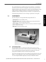
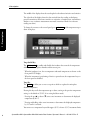
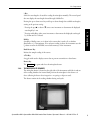
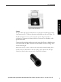
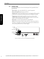
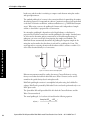
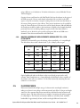
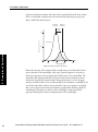
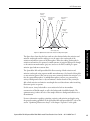

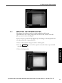

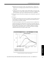
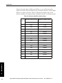
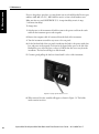
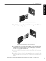

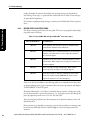
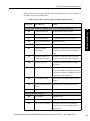
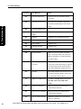
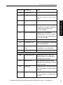
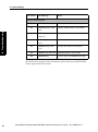
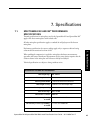
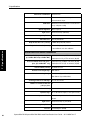
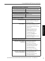
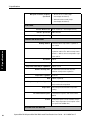
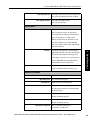
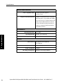
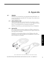
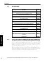
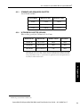
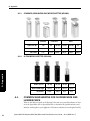
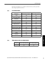
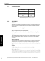
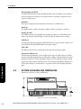


![1] n T169](http://vs1.manualzilla.com/store/data/005696581_1-b5b272b0c99ea5fca956b563015d9b67-150x150.png)