1
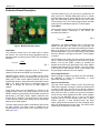
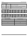
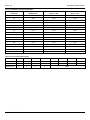
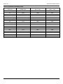
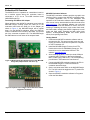
MIC2870 Evaluation Board
1.5A Synchronous Boost Flash LED Driver
with I2C Interface
General Description
Getting Started
The MIC2870 is a high-current, high-efficiency flash LED
driver for one or two high-brightness camera flash LEDs.
1. Connect external supply to the VIN terminals.
The LED driver current is generated by an integrated
inductive boost converter with 2MHz switching frequency
which allows the use of very small inductor and output
capacitor. These features make the MIC2870 an ideal
solution for high-resolution camera phone LED flash light
driver applications.
MIC2870 supports two 750mA white-LEDs (WLEDs) or a
single 1.5A WLED configuration. When two WLEDs are
connected, their currents are matched automatically.
MIC2870 operates in either flash or torch modes that can
2
be controlled through either I C interface or external pins.
The brightness in the flash and torch mode can be
adjusted via two external resistors individually. High-speed
2
mode I C interface provides a simple control at a clock
speed up to 3.4MHz to support most camera functions
such as auto-focus, white balance, and image capture.
Datasheets and support documentation are available on
Micrel’s web site at: www.micrel.com.
Requirements
The MIC2870 evaluation board requires a bench input
power source that is adjustable from 2.7V to 5.0V and is
able to deliver greater than 4.5A at 2.7V.
Precautions
The evaluation board does not have reverse polarity
protection. Applying a negative voltage across the VIN
terminal to GND terminal may damage the device. The
MIC2870 evaluation board is tailored for a Li-ion range
input supply voltage. It should not exceed 5.0V on the
input.
Apply desired input voltage to the VIN (J1) and ground
(J2) terminals of the evaluation board, paying careful
attention to polarity and supply range (2.7V to 5.0V).
An ammeter may be placed between the power supply
and the input terminal of the evaluation board. Ensure
that the supply voltage is monitored at the input
terminals. The ammeter and /or power lead resistance
can reduce the voltage supplied to the input.
2. Enable/Disable the MIC2870.
The MIC2870 evaluation board has an enable (EN) pin
(J5). The MIC2870 is in standby mode when the EN
pin is asserted high. Setting a jumper at TP1 can
connect the EN pin to VIN through a pull-high resistor.
If this pin is driven low for more than 1s, the IC is
shutdown. This pin is pulled down by an internal
resistor. Alternatively, the IC can be enabled or
2
disabled by software through I C interface.
3. Enable/Disable the torch mode.
The TEN (J3) is the torch mode enable pin. When this
pin is high, the torch mode is initiated. Setting a jumper
at TP4 can connect TEN pin to VIN through a resistor.
If this pin is left floating, it is pulled-down internally by a
built-in 1µA current source when the device is
enabled. Alternatively, the torch mode can be enabled
2
or disabled by software through I C interface.
4. Enable/Disable the flash mode.
The FEN (TP2 upper pin) is the flash mode enable pin.
A low-to-high transition at this pin initiates the flash
mode and the flash mode timer. Setting a jumper at
TP2 can connect FEN to VIN through a resistor. If this
pin is left floating, it is pulled-down internally by a builtin 1µA current source when the device is enabled.
Alternatively, the flash mode can be enabled or
2
disabled by software through I C interface.
Ordering Information
Part Number
Description
MIC2870YFT EV
MIC2870 Evaluation Board
MICUSB Dongle EV
I C Serial Programmer Board
2
Micrel Inc. • 2180 Fortune Drive • San Jose, CA 95131 • USA • tel +1 (408) 944-0800 • fax + 1 (408) 474-1000 • http://www.micrel.com
September 24, 2013
Revision 1.2
Micrel, Inc.
MIC2870 Evaluation Board
Getting Started (Continued)
5. Enable/Disable flash inhibit.
The FI (TP3 upper pin) is the flash inhibit pin. When
this pin is high in flash mode, both LED1 (D1) and
LED2 (D2) currents are changed from the flash mode
current level to the torch mode current level. When this
pin is low, both LED1 (D1) and LED2 (D2) currents are
changed from torch mode current level back to the
original flash mode current level. Setting a jumper at
TP3 can connect FI to VIN through a resistor. If this
pin is left floating, it is pulled-down internally by a builtin 1µA current source when the device is enabled.
6. Graphic user interface support.
Graphical user interface software can be used with the
MICUSB Dongle EV allowing configuration and testing
of the MIC2870 with a standard computer. For more
detail, refer to the Evaluation Software section.
September 24, 2013
2
Revision 1.2
Micrel, Inc.
MIC2870 Evaluation Board
Evaluation Board Description
The flash inhibit (FI) pin can be used to synchronize the
flash current to a handset GSM pulse event to prevent
excessive battery droop. When FEN and FI pins are both
high, the flash mode current is limited to the torch mode
current setting. The FI Pin is also functional when the flash
2
mode current is enabled through the I C flash register.
Torch Mode
The maximum torch mode level can be adjusted through
an external resistor connecting to the TRSET pin
according to Equation 2:
ILED(MAX) =
Flash Mode
The maximum current level in the flash mode is 750mA
per channel. This current level can be adjusted through an
external resistor connecting to the FRSET pin according to
Equation 1:
7500
R FRSET
Like the flash mode current, the torch mode current can be
set to a fraction of the maximum torch mode level (either
default or set by the TRSET resistor) by selecting the
desired torch current level percentage in the torch register
2
(Address 02h) through the I C interface. The torch current
is the product of the maximum torch current setting and
the percentage selected in the torch register.
Eq. 1
Alternatively, the default maximum value of 750mA per
channel is used when the FRSET pin is grounded.
Overvoltage Protection
When the output voltage rises above the OVP threshold,
the MIC2870 is turned off automatically to avoid
permanent damage to the IC.
The flash mode current can be initiated at the preset
FRSET brightness level by asserting FEN pin high or by
2
setting the I C flash control register (address 01h) for the
desired flash duration, subjected to the flash safety timeout
setting. The flash mode current is terminated when the
2
FEN pin is brought low and the I C flash register is
cleared.
Open Circuit Detection
The open-circuit detector (OCD) is active only when the
LED current regulator is turned on. When the external LED
is missing or fails open, the LED1/2 pin voltage is pulled to
near the ground potential by the internal current sink. If
both LEDs are open or missing, the open-circuit detector
would force the boost regulator and LED current regulator
to turn off. The MIC2870 will try to turn on the boost
regulator and LED current regulator again after a 100ms
timeout. However, in most practical cases, the boost
output voltage would rise above the OVP threshold, when
both LED channels have an open fault. The OVP function
would cause the MIC2870 to shut down.
Flash mode current can be adjusted to a fraction of the
maximum flash mode level (either default or set by the
FRSET resistor) by selecting the desired flash current level
percentage in the flash control register (Address 01h)
2
through the I C interface. The flash current is the product
of the maximum flash current setting and the percentage
selected in the flash register.
The flash safety timeout feature automatically shuts down
the flash current if the flash mode is enabled for an
extended period of time. Refer to the “Flash Safety Timer”
setting in Table 4.
September 24, 2013
Eq. 2
Alternatively, the default maximum value of 187.5mA per
channel is used when the TRSET pin is grounded. The
torch mode operation is activated by asserting the TEN pin
2
high or by setting the I C torch register (address 02h) for
the desired duration. The torch mode current is terminated
2
when the TEN pin is brought low and the I C torch register
is cleared.
Figure 1. MIC2870 Evaluation Board
ILED(MAX) =
7500
4R TRSET
3
Revision 1.2
Micrel, Inc.
MIC2870 Evaluation Board
2
Short-Circuit Detection
Like the open-circuit detector, the short-circuit detector is
active only when the current regulator is turned on. If either
one or both of the external LEDs fail as a short, the shortcircuit detector would force the MIC2870 to turn off. The
MIC2870 will try to turn on the boost regulator and LED
current regulator again after a 100ms timeout. If the short
condition persists, the whole cycle repeats again.
Prolonged operation in short-circuit condition is not
recommended as it may damage the device.
I C Registers
MIC2870 contains three 8-bit read/write registers having
an address from 00h to 02h for operation control as shown
in Table 1. These registers are reset to their default values
in power-on-reset (POR) event. In other words, they hold
their previous contents when the chip is shutdown as long
as supply voltage is above 1.5V (typical).
Master Control / Status Register [00h]
The master control / status register allows the MIC2870 to
2
be enabled by the I C interface -- setting the ON [ ] bit high
has the same effect as asserting EN pin. The LED short
bit, LED_SHT[ ] is set if any or both of the LED is shorted
to OUT, while the LED open bit, LED_OP[ ] is asserted
only when both LED are open circuit. The thermal
shutdown bit, TSD[ ] is set when the junction temperature
of the MIC2870 is higher than 160°C. The bit names and
assignment of all the bits in the master control / status
register and their default values are shown in Table 2.
2
I C Interface
The timing diagram shows the communications required
2
for write and read operations via the I C interface. The
black lines show master communications and the red lines
show the slave communications. During a write operation
the master must drive SDA and SCL for all stages except
the acknowledgement (A) shown in red, which are
provided by the slave (MIC2870).
Flash Control Register [01h]
The flash mode enable, flash safety timer and flash mode
current are configurable via the flash control register. The
flash control register contains the FTMR[ ] bits, FEN[ ] bit,
and FCUR bits. The FTMR[ ] bits set the flash safety timer
duration. The FEN[ ] bit has the same function as the FEN
pin. When the FEN[ ] is set the flash mode is enabled. The
FCUR[ ] bits set the flash mode current in 16 steps from
100% down to 18% of the maximum LED flash current
which is set by the FRSET resistor. The detail description
of the bit names of all the bits and their assignment in the
flash control register and their default values are shown in
Table 3. The details of flash timeout duration setting and
flash mode current setting can be referred to Table 4 and
Table 5.
Torch Control Register [02h]
The torch mode enable, torch mode current, and flash
inhibit are configurable via the torch control register. The
torch control register contains the TCUR[ ] bits, TEN[ ] bit,
and FI[ ] bit. The TCUR[ ] bits set the torch mode current in
16 steps from 100% down to 18% of the maximum LED
torch current which is set by the TRSET resistor. The
TEN[ ] bit has the same function as the TEN pin. When the
TEN[ ] bit is set the torch mode is enabled. The FI[ ] bit has
the same function as the FI pin. When the FI[ ] bit is set,
the flash mode current is reduced to the torch mode
current setting. The detail description of the bit names of
all the bits and their assignment in the torch control
register and their default values are shown in Table 6. The
detail of the torch mode current setting is shown in
Table 7.
2
Figure 2. I C Timing Example
The read operation begins firstly with a data-less write to
select the register address from which to read. Then a
restart sequence is issued, and then a read command
followed by the data read.
The MIC2870 responds to a slave address of hex 0xB4
and 0xB5 for write and read operations respectively, or
binary 1011010X (where X is the read/write bit).
The register address is eight bits wide and carries the
address of the MIC2870 register to be operated upon.
Only the lower three bits are used.
September 24, 2013
4
Revision 1.2
Micrel, Inc.
MIC2870 Evaluation Board
Table 1. MIC2870 Register Map
Register Address
Register Name
Description
00h
Master Control/ Status
01h
Flash Control
Flash Mode Current, Flash Mode Enable, and Flash Timeout Control Register
02h
Torch Control
Torch Mode Current and Torch Mode Enable Control Register
Chip Enable, Control and Status Register
Table 2. Master Control Register [00h]
D7
D6
D5
D4
D3
D2
D1
D0
Name
Reserved
Reserved
Reserved
Reserved
ON
LED_SHT
LED_OP
TSD
Access
R
R
R
R
R/W
R
R
R
Default Value
0
0
0
0
0
0
0
0
Table 3. Flash Control Register [01h]
BIT
D7
D6
D5
D4
D3
D2
D1
D0
Name
FTMR
FTMR
FTMR
FEN
FCUR
FCUR
FCUR
FCUR
Access
R/W
R/W
R/W
R/W
R/W
R/W
R/W
R/W
Default Value
111
0
0000
Table 4. Flash Safety Timer Setting [FTMR]
Register Value [D7:D5] of 01h
Flash Timeout Duration (ms)
111
1250
110
1093.75
101
937.5
100
781.25
011
625
010
468.75
001
312.5
000
156.25
September 24, 2013
5
Revision 1.2
Micrel, Inc.
MIC2870 Evaluation Board
Table 5. Flash Mode Current Setting [FCUR]
Percentage of Maximum
Current (%)
Register Value
[D3:D0] of 01h
Current Per Channel (mA)
(RFRSET = 0Ω)
Combined Current (mA)
(RFRSET = 0Ω)
100
0000
750.0
1500.0
90
0001
675.0
1350.0
80
0010
600.0
1200.0
70
0011
525.0
1050.0
63
0100
472.5
945.0
56
0101
420.0
840.0
50
0110
375.0
750.0
44.7
0111
335.3
670.5
39.8
1000
298.5
597.0
35.5
1001
266.3
532.5
31.6
1010
237.0
474.0
28.2
1011
211.5
423.0
25.1
1100
188.3
376.5
22.4
1101
168.0
336.0
20
1110
150.0
300.0
18
1111
135.0
270.0
Table 6. Torch Control Register [02h]
BIT
D7
D6
D5
D4
D3
D2
D1
D0
Name
Reserved
Reserved
FI
TEN
TCUR
TCUR
TCUR
TCUR
Access
RO
RO
R/W
R/W
R/W
R/W
R/W
R/W
0
0
0
0
Default Value
September 24, 2013
6
0000
Revision 1.2
Micrel, Inc.
MIC2870 Evaluation Board
Table 7. Torch Mode Current Setting [TCUR]
Percentage of Maximum
Current (%)
Register Value
[D3:D0] of 02h
Current Per Channel (mA)
(RTRSET = 0Ω)
Combined Current (mA)
(RTRSET = 0Ω)
100
0000
187.5
375.0
90
0001
168.8
337.5
80
0010
150.0
300.0
70
0011
131.3
262.5
63
0100
118.1
236.3
56
0101
105.0
210.0
50
0110
93.8
187.5
44.7
0111
83.8
167.6
39.8
1000
74.6
149.3
35.5
1001
66.6
133.1
31.6
1010
59.3
118.5
28.2
1011
52.9
105.8
25.1
1100
47.1
94.1
22.4
1101
42.0
84.0
20
1110
37.5
75.0
18
1111
33.8
67.5
September 24, 2013
7
Revision 1.2
Micrel, Inc.
MIC2870 Evaluation Board
Evaluation Kit Overview
The MIC2870 can be operated as a standalone board or
as a modular system where the evaluation board is
2
connected to a PC via an I C-to-USB interface board
(MICUSB Dongle EV).
MIC2870 Evaluation Software
The MIC2870 evaluation software provides a graphic user
interface (GUI) to program the MIC2870 evaluation board.
A complete application note on the installation and
operation of the evaluation software and the USB adapter
user manual can be downloaded from Micrel’s web site at
www.micrel.com. The evaluation software can read and
2
write to registers inside the MIC2870 IC device via I C for
enabling or disabling the device, torch mode, flash mode,
and flash inhibit; changing the WLEDs’ brightness in torch
mode and flash mode; changing the flash safety timer
duration; enabling/disabling breath and strobe special
effects; and reporting fault status.
Connecting the USB-to-I2C Adapter
When interfacing the MIC2870 evaluation board with the
MICUSB Dongle, carefully match the GND pin of the
evaluation board with the GND pin of the adapter (as
shown in Figure 3, the MICUSB Dongle will be upside
down). On the MIC2870 evaluation board, the GND pin
location is labeled on the left side of the board. It is the first
pin of the connecter receptacle JP1. The MICUSB Dongle
has GND labeled on both sides of the adapter board.
Getting Started
1. Download the MIC2870 evaluation software and run
the setup.exe file. This step may take some time and
require an internet connection to update the computer
to .NET Framework 3.5.
2. Install the MICUSB Dongle EV driver from FTDI.
Double-click on the file CDM20828_Setup.exe. The
latest driver can be downloaded from the FTDI
website: www.ftdichip.com.
3. After installing the driver, locate the virtual COM port
created by the FTDI driver in the Device Manager
Menu, under Ports (COM & LPT). The corresponding
port will have FTDI listed as the manufacturer.
Figure 3. MIC2870 Evaluation Board Interfaces with MICUSB
Dongle EV (adapter bottom side faces up)
4. Connect the MIC2870 evaluation board to the PC via
the MICUSB Dongle EV. Power the MIC2870
evaluation board VIN input.
5. Set the mini slide switch SW1 on the MICUSB Dongle
2
EV. The SW1 should be toggled to the I C position as
shown in Figure 4.
6. Open the MIC2870 evaluation software in Programs
under the Start Menu.
Figure 4. Top Side of the Adapter with the Mini Slide Switch
2
Toggled to I C Position
September 24, 2013
8
Revision 1.2
Micrel, Inc.
MIC2870 Evaluation Board
Evaluation Software
The MIC2870 evaluation software graphic user interface
(GUI) is shown in Figure 5 and Figure 6. When the
evaluation software is just started, it is default in offline
mode as shown on the right of the top menu bar in Figure
5. The offline mode is only for running the software without
the communication or connection with the MIC2870
evaluation board.
At the right side of the GUI panel which is the MIC2870
Control panel, user can perform the following MIC2870
operation:
1. Check or uncheck the “Enabled” option to enable or
disable the MIC2870 device.
2. Change the flash safety timer duration setting from 0
to 7 which corresponding to 8 options from 156ms to
1250ms. Please refer to Table 4 for details.
To control the MIC2870 evaluation board with the software
GUI, the user firstly has to click the “Test” button. If the
connection from the PC to the dongle and then to the
MIC2870 EVB is fine as instructed in Connecting the USB2
to-I C Adapter section and in steps 4 and 5 in the Getting
Started section, the “Target OK” will be shown up at the
status bar at the bottom of the GUI as shown Figure 5.
3. Adjust the flash brightness with the slide bar from
100% to 18% of the maximum LED current in flash
mode in 16 steps. The maximum is on the left and the
minimum is on the right.
4. Fire flash or reset flash by clicking the flash mode
enable button.
If the connection is not good, the “Target Not Detected” will
be shown up at the status bar and the user has to check
with the cable connections before proceeding to the next
step. When the “Target OK” status is shown, the user can
click on the “Offline Mode” at the menu bar to change it to
“Direct Editing Mode”. When the “Direct Editing Mode” is
shown up at the top menu bar and the “Direct Editing
Mode Active” is indicated at the status bar as shown in
Figure 6, the software GUI allows the user to control the
operation of the MIC2870 evaluation board.
5. Check or uncheck flash inhibit option to enable or
disable the flash inhibit function.
6. Adjust the torch brightness with the slide bar from
100% to 18% of the maximum LED current in torch
mode in 16 steps. The maximum is on the left and the
minimum is on the right.
7. Set or reset torch by clicking on the torch mode enable
button.
8. Click the “Breath” button, “Strobe” button, and set
delay time options for special effects demonstration.
Introduction to the GUI Panel
At the left side of the GUI panel, user can check with the
MIC2870 registers information and perform read and write
operation to the IC registers. At the middle of the GUI
panel, user can click the “Enable” option to enable the
register polling.
9. Fault indication will be shown at the bottom of the
control panel if the register polling is enabled and fault
conditions are detected. The current detected fault
value can be cleared by clicking the “Clear” button.
2
Setting of I C Data Rate
2
The data rate of the I C communication can be set at the
2
pull-down menu from the “I C” menu at the top menu bar
as shown in Figure 7. User can set the data rate to
100kbps, 400kbps, or 3.4Mbps from the pull-down menu.
September 24, 2013
9
Revision 1.2
Micrel, Inc.
MIC2870 Evaluation Board
Figure 5. MIC2870 Evaluation Software GUI in Offline Mode
Figure 6. MIC2870 Evaluation Software GUI in Direct Editing Mode
Figure 7. Setting Data Rate from Pulldown Menu
September 24, 2013
10
Revision 1.2
Micrel, Inc.
MIC2870 Evaluation Board
Evaluation Board Schematic
September 24, 2013
11
Revision 1.2
Micrel, Inc.
MIC2870 Evaluation Board
Bill of Materials
Item
C3
Part Number
C5
AVX
C1608X5R1A475K080AC
TDK
C6
C1608X5R1A225K080AC
TDK
06033D104KAJ2A
AVX
TDK
0603ZD105KAT2A
AVX
R1, R2
CDRH4D28CLDNP-1R0PC
LQH44PN1R0NP0L
CRCW06034K70FKEA
(3)
Murata
C1608X5R1E104K
GRM188R61A105KA61D
Murata
Ceramic Capacitor 2.2µF, 10V, X5R, 0603
1
Ceramic Capacitor 0.1µF, 25V, X5R, 0603
1
Ceramic Capacitor 1µF, 10V, X5R, 0603
1
1
Inductor 1µH, 2.45A, 36mΩ, L4.0mm x W4.0mm x H1.65mm
Murata
Vishay/Dale
(5)
(6)
Panasonic
R6, R7,
R8, R9
CRCW060310K0FKEA
Vishay/Dale
U1
1
Inductor 1µH, 3.0A, 14mΩ, L5.1mm x W5.1mm x H3.0mm
(4)
ERA3AEB103V
SML-LXL99UWC-TR/5
Ceramic Capacitor 4.7µF, 10V, X5R, 0603
TDK
Sumida
R3, R4
D1, D2
Qty.
AVX
Murata
C1608X5R1A105K080AC
L1
(2)
GRM188R61A225KE34D
GRM188R61C104KA01D
Description
(1)
0603ZD475KAT2A
0603ZD225KAT2A
C4
Manufacturer
(7)
Lumex
Resistor 4.7kΩ, 1%, 1/10W, 0603
2
Resistor 10kΩ, 0.1%, 1/10W, 0603
2
Resistor 10kΩ, 1%, 1/10W, 0603
4
LED SQ 5W COOL WHT 6000K SMD, 190lm
2ER103CW06000002
Edison-Opto
MIC2870YFT
Micrel, Inc.
(8)
(9)
2
LED, 3W, COOL WHT 6000K SMD, 210lm
2
1.5A Synchronous Boost Flash LED Driver with I C Interface
1
Notes:
1. AVX: www.avx.com.
2. TDK: www.tdk.com.
3. Murata: www.murata.com.
4. Sumida: www.sumida.com.
5. Vishay: www.vishay.com.
6. Panasonic: www.panasonic.com
7. Lumex: www.lumex.com.
8. Edison-Opto: www.edison-opto.com
9. Micrel, Inc.: www.micrel.com.
September 24, 2013
12
Revision 1.2
Micrel, Inc.
MIC2870 Evaluation Board
PCB Layout Recommendations
Top Layer
Bottom Layer
September 24, 2013
13
Revision 1.2
Micrel, Inc.
MIC2870 Evaluation Board
MICREL, INC. 2180 FORTUNE DRIVE SAN JOSE, CA 95131 USA
TEL +1 (408) 944-0800 FAX +1 (408) 474-1000 WEB http://www.micrel.com
Micrel makes no representations or warranties with respect to the accuracy or completeness of the information furnished in this data sheet. This
information is not intended as a warranty and Micrel does not assume responsibility for its use. Micrel reserves the right to change circuitry,
specifications and descriptions at any time without notice. No license, whether express, implied, arising by estoppel or otherwise, to any intellectual
property rights is granted by this document. Except as provided in Micrel’s terms and conditions of sale for such products, Micrel assumes no liability
whatsoever, and Micrel disclaims any express or implied warranty relating to the sale and/or use of Micrel products including liability or warranties
relating to fitness for a particular purpose, merchantability, or infringement of any patent, copyright or other intellectual property right.
Micrel Products are not designed or authorized for use as components in life support appliances, devices or systems where malfunction of a product
can reasonably be expected to result in personal injury. Life support devices or systems are devices or systems that (a) are intended for surgical
implant into the body or (b) support or sustain life, and whose failure to perform can be reasonably expected to result in a significant injury to the user. A
Purchaser’s use or sale of Micrel Products for use in life support appliances, devices or systems is a Purchaser’s own risk and Purchaser agrees to fully
indemnify Micrel for any damages resulting from such use or sale.
© 2013 Micrel, Incorporated.
September 24, 2013
14
Revision 1.2