1
UM1915
User Manual
STM8AF Safety Manual
Introduction
The STM8A is a family of microcontrollers designed for automotive applications, with different
memory densities, packages and peripherals.
This document describes how to use the STM8AF series of microcontrollers in the context of
a safety-related system (STM8A-SafeASIL functional safety package), specifying the user's
responsibilities for installation and operation, in order to reach the targeted safety integrity
level.
This manual applies to the following STM8AF series:
The STM8AF62 line that is the mainstay of the automotive STM8A 8 bit MCU:
– The low density devices with 8 Kbytes of Flash memory: STM8AF6223/26
– The medium density with 16 to 32 Kbytes of Flash memory: STM8AF624x,
STM8AF6266/68, STM8AF612x/4x and STM8AF6166/68
– The high density devices with 32 to 128 Kbytes of Flash memory:
STM8AF6269/8x/Ax and STM8AF6178/99/9A
The STM8AF52 line: STM8AF automotive MCUs with CAN:
– The high density devices with 32 to 128 Kbytes of Flash memory: STM8AF52xx and
STM8AF51xx
If the STM8AF microcontrollers are used in adherence to this manual, the system designer
can avoid going into the details of the functional safety design and validation, to give an
estimation about the impact to the overall safety function.
This manual is written in compliance with ISO 26262. It also indicates how to use the
STM8AF MCUs in the context of other functional safety standards such as IEC 61508. This
manual and FMEDA data were developed in cooperation with the safety expertise company
YOGITECH, using their fault Robust Methodology (fRMethodology).
The safety analysis summarized in this manual, takes into account the variation in terms of
memory size, number of internal peripherals and the different packages available among
the different part numbers of the STM8A microcontrollers family.
This manual has to be read along with the technical documentation on related part numbers
available on www.st.com/stm8.
July 2015
DocID028066 Rev 1
1/59
www.st.com
1
Content
UM1915
Content
1
2
3
About this document . . . . . . . . . . . . . . . . . . . . . . . . . . . . . . . . . . . . . . . . 7
1.1
Purpose and scope . . . . . . . . . . . . . . . . . . . . . . . . . . . . . . . . . . . . . . . . . . 7
1.2
Terms and abbreviations . . . . . . . . . . . . . . . . . . . . . . . . . . . . . . . . . . . . . . 7
1.3
Reference normative . . . . . . . . . . . . . . . . . . . . . . . . . . . . . . . . . . . . . . . . . 8
1.4
Annexes . . . . . . . . . . . . . . . . . . . . . . . . . . . . . . . . . . . . . . . . . . . . . . . . . . . 8
STM8AFxxxx device development process . . . . . . . . . . . . . . . . . . . . . . 9
2.1
STMicroelectronics standard development process . . . . . . . . . . . . . . . . . . 9
2.2
YOGITECH fRMethodology process . . . . . . . . . . . . . . . . . . . . . . . . . . . . . 9
STM8AF Safety Architecture . . . . . . . . . . . . . . . . . . . . . . . . . . . . . . . . . 10
3.1
Introduction . . . . . . . . . . . . . . . . . . . . . . . . . . . . . . . . . . . . . . . . . . . . . . . 10
3.1.1
2/59
Definition of the Safety Element out of Context . . . . . . . . . . . . . . . . . . . 10
3.2
STM8AF as a SEooC . . . . . . . . . . . . . . . . . . . . . . . . . . . . . . . . . . . . . . . . 10
3.3
Assumed safety requirements . . . . . . . . . . . . . . . . . . . . . . . . . . . . . . . . . .11
3.3.1
The target safety metrics (ASIL, SPFM, LFM and PMHF) . . . . . . . . . . . 12
3.3.2
The assumed target time intervals (FTTI and MPFDI) . . . . . . . . . . . . . . 13
3.4
Electrical specifications and environment limits . . . . . . . . . . . . . . . . . . . . 14
3.5
Systematic safety integrity . . . . . . . . . . . . . . . . . . . . . . . . . . . . . . . . . . . . 15
3.6
Safety mechanisms/measures . . . . . . . . . . . . . . . . . . . . . . . . . . . . . . . . . 15
3.6.1
STM8A CORE . . . . . . . . . . . . . . . . . . . . . . . . . . . . . . . . . . . . . . . . . . . . 15
3.6.2
Program FLASH memory . . . . . . . . . . . . . . . . . . . . . . . . . . . . . . . . . . . 17
3.6.3
Data EEPROM memory . . . . . . . . . . . . . . . . . . . . . . . . . . . . . . . . . . . . . 18
3.6.4
RAM memory . . . . . . . . . . . . . . . . . . . . . . . . . . . . . . . . . . . . . . . . . . . . . 18
3.6.5
Boot ROM . . . . . . . . . . . . . . . . . . . . . . . . . . . . . . . . . . . . . . . . . . . . . . . 19
3.6.6
Basic enhanced CAN (beCAN) . . . . . . . . . . . . . . . . . . . . . . . . . . . . . . . 19
3.6.7
LINUART . . . . . . . . . . . . . . . . . . . . . . . . . . . . . . . . . . . . . . . . . . . . . . . . 20
3.6.8
USART . . . . . . . . . . . . . . . . . . . . . . . . . . . . . . . . . . . . . . . . . . . . . . . . . . 21
3.6.9
I2C . . . . . . . . . . . . . . . . . . . . . . . . . . . . . . . . . . . . . . . . . . . . . . . . . . . . . 22
3.6.10
SPI . . . . . . . . . . . . . . . . . . . . . . . . . . . . . . . . . . . . . . . . . . . . . . . . . . . . . 22
3.6.11
Analog to Digital Converter (ADC) . . . . . . . . . . . . . . . . . . . . . . . . . . . . . 23
3.6.12
Basic timer (TIM 4) . . . . . . . . . . . . . . . . . . . . . . . . . . . . . . . . . . . . . . . . 25
3.6.13
GPIO – PORT A/B/C/D/E/F/G/H . . . . . . . . . . . . . . . . . . . . . . . . . . . . . . 26
DocID028066 Rev 1
UM1915
Content
3.7
3.6.14
Address and Data bus . . . . . . . . . . . . . . . . . . . . . . . . . . . . . . . . . . . . . . 26
3.6.15
Supply voltage system . . . . . . . . . . . . . . . . . . . . . . . . . . . . . . . . . . . . . . 27
3.6.16
Reset and Clock control subsystems . . . . . . . . . . . . . . . . . . . . . . . . . . . 27
3.6.17
Auto-wakeup timer (AWU) . . . . . . . . . . . . . . . . . . . . . . . . . . . . . . . . . . . 28
3.6.18
Watchdogs (IWDG, WWDG) . . . . . . . . . . . . . . . . . . . . . . . . . . . . . . . . . 28
3.6.19
Debug/ SWIM (single wire interface module) . . . . . . . . . . . . . . . . . . . . 29
3.6.20
Interrupt controller (NVIC and EXTI) . . . . . . . . . . . . . . . . . . . . . . . . . . . 29
3.6.21
Latent fault detection . . . . . . . . . . . . . . . . . . . . . . . . . . . . . . . . . . . . . . . 29
3.6.22
Disable and periodic cross-check of unintentional activation of unused
peripherals . . . . . . . . . . . . . . . . . . . . . . . . . . . . . . . . . . . . . . . . . . . . . . . 30
Assumption of Use (AoU) . . . . . . . . . . . . . . . . . . . . . . . . . . . . . . . . . . . . . 30
3.7.1
4
Safety Analysis Results . . . . . . . . . . . . . . . . . . . . . . . . . . . . . . . . . . . . . 35
4.1
4.2
5
List of Assumptions of Use (AoU) . . . . . . . . . . . . . . . . . . . . . . . . . . . . . 31
Hardware random failure analysis . . . . . . . . . . . . . . . . . . . . . . . . . . . . . . 35
4.1.1
Safety analysis result customization . . . . . . . . . . . . . . . . . . . . . . . . . . . 36
4.1.2
General requirements for Freedom From Interferences (FFI) . . . . . . . . 36
Dependent failures analysis . . . . . . . . . . . . . . . . . . . . . . . . . . . . . . . . . . . 37
4.2.1
Power supply . . . . . . . . . . . . . . . . . . . . . . . . . . . . . . . . . . . . . . . . . . . . . 37
4.2.2
Clock . . . . . . . . . . . . . . . . . . . . . . . . . . . . . . . . . . . . . . . . . . . . . . . . . . . 38
List of evidences . . . . . . . . . . . . . . . . . . . . . . . . . . . . . . . . . . . . . . . . . . . 39
Appendix A Appendix A Overview of fRMethodology . . . . . . . . . . . . . . . . . . . . 40
A.1
The essence of fRMethodology. . . . . . . . . . . . . . . . . . . . . . . . . . . . . . . . . 40
A.2
fRMethodology and its flow . . . . . . . . . . . . . . . . . . . . . . . . . . . . . . . . . . . . 40
A.3
fRTools . . . . . . . . . . . . . . . . . . . . . . . . . . . . . . . . . . . . . . . . . . . . . . . . . . . 42
Appendix B Appendix B Change impact analysis for other safety standards . 44
B.1
IEC 60730-1:2010 . . . . . . . . . . . . . . . . . . . . . . . . . . . . . . . . . . . . . . . . . . . 44
B.2
Architectural categories. . . . . . . . . . . . . . . . . . . . . . . . . . . . . . . . . . . . . . . 44
B.3
Safety metrics recomputation . . . . . . . . . . . . . . . . . . . . . . . . . . . . . . . . . . 45
B.4
Work products . . . . . . . . . . . . . . . . . . . . . . . . . . . . . . . . . . . . . . . . . . . . . . 51
B.5
IEC 61508 . . . . . . . . . . . . . . . . . . . . . . . . . . . . . . . . . . . . . . . . . . . . . . . . . 53
B.6
Architectural categories. . . . . . . . . . . . . . . . . . . . . . . . . . . . . . . . . . . . . . . 54
B.7
Safety metrics re-computation. . . . . . . . . . . . . . . . . . . . . . . . . . . . . . . . . . 54
DocID028066 Rev 1
3/59
4
Content
UM1915
B.8
6
4/59
Work products . . . . . . . . . . . . . . . . . . . . . . . . . . . . . . . . . . . . . . . . . . . . . . 56
Revision history . . . . . . . . . . . . . . . . . . . . . . . . . . . . . . . . . . . . . . . . . . . 58
DocID028066 Rev 1
UM1915
List of Tables
List of Tables
Table 1.
Table 2.
Table 3.
Table 4.
Table 5.
Table 6.
Table 7.
Table 8.
Table 9.
Table 10.
Table 11.
Table 12.
Terms and abbreviations . . . . . . . . . . . . . . . . . . . . . . . . . . . . . . . . . . . . . . . . . . . . . . . . . . . 7
List of STM8AF Assumed Requirements . . . . . . . . . . . . . . . . . . . . . . . . . . . . . . . . . . . . . . 12
Target safety metric values at the item level . . . . . . . . . . . . . . . . . . . . . . . . . . . . . . . . . . . 13
List of safety mechanisms . . . . . . . . . . . . . . . . . . . . . . . . . . . . . . . . . . . . . . . . . . . . . . . . . 31
List of general requirements for FFI . . . . . . . . . . . . . . . . . . . . . . . . . . . . . . . . . . . . . . . . . . 36
Level of detail in fRMethodology . . . . . . . . . . . . . . . . . . . . . . . . . . . . . . . . . . . . . . . . . . . . 42
IEC 60730 required safety mechanism for Class B/C compliance. . . . . . . . . . . . . . . . . . . 46
IEC 60730 work product grid . . . . . . . . . . . . . . . . . . . . . . . . . . . . . . . . . . . . . . . . . . . . . . . 51
Some reference architectures for IEC 61508 . . . . . . . . . . . . . . . . . . . . . . . . . . . . . . . . . . . 54
Mapping between this document content and IEC 61508-2 Annex D
requirements . . . . . . . . . . . . . . . . . . . . . . . . . . . . . . . . . . . . . . . . . . . . . . . . . . . . . . . . . . . 56
IEC 61508 work product grid . . . . . . . . . . . . . . . . . . . . . . . . . . . . . . . . . . . . . . . . . . . . . . . 57
Document revision history . . . . . . . . . . . . . . . . . . . . . . . . . . . . . . . . . . . . . . . . . . . . . . . . . 58
DocID028066 Rev 1
5/59
5
List of Figures
UM1915
List of Figures
Figure 1.
Figure 2.
Figure 3.
Figure 4.
Figure 5.
Figure 6.
6/59
Definition of the STM8AF as a SEooC . . . . . . . . . . . . . . . . . . . . . . . . . . . . . . . . . . . . . . . . 11
Relationship between assumptions and SEooC development . . . . . . . . . . . . . . . . . . . . . . 11
STM8AF FTTI allocation and cycle time . . . . . . . . . . . . . . . . . . . . . . . . . . . . . . . . . . . . . . . 14
The fRMethodology flow for ISO 26262 and IEC 61508. . . . . . . . . . . . . . . . . . . . . . . . . . . 41
Overview of the YOGITECH fRTool suite . . . . . . . . . . . . . . . . . . . . . . . . . . . . . . . . . . . . . . 43
Correlation matrix between SIL and ASIL. . . . . . . . . . . . . . . . . . . . . . . . . . . . . . . . . . . . . . 53
DocID028066 Rev 1
UM1915
About this document
1
About this document
1.1
Purpose and scope
This document describes how to use the STM8AF microcontrollers in the context of a
safety-related system, specifying the user's responsibilities for installation and operation, in
order to reach the desired safety integrity level.
This document is useful to system designers willing evaluate the safety of their solution.
1.2
Terms and abbreviations
Table 1. Terms and abbreviations
Acronym
Definition
AoU
Assumptions to Use
ASIL
Automotive Safety Integrity Level
CCF
Common Cause Failure
COTS
Commercial Off-the-Shelf
CPU
Central Processing Unit
CRC
Cyclic Redundancy Check
DC
Diagnostic Coverage
DTI
Diagnostic Test Interval
FIT
Failure In Time
FTTI
Fault Tolerant Time Interval
FMEA
Failure Mode Effect Analysis
FMEDA
Failure Mode Effect Diagnostic Analysis
HFT
Hardware Fault Tolerance
HW
Hardware
INTC
Interrupt Controller
LFM
Latent Fault Metric
MCU
Microcontroller Unit
MPF
Multiple Point Failures
MPFDI
Multiple Point Fault Detection Interval
NVIC
Nested vector interrupt controller
PMHF
Probabilistic Metric for random Hardware Failures
QM
Quality Management
SFF
Safe Failure Fraction
SIL
Safety Integrity level
SEooC
Safety Element Out of Context
SPF
Single Point Fault
DocID028066 Rev 1
7/59
58
About this document
UM1915
Table 1. Terms and abbreviations (continued)
1.3
Acronym
Definition
SPFM
Single Point Fault Metric
SW
Software
Reference normative
This document is written in compliance with the ISO 26262 international standard for
functional safety of electrical and/or electronic (E/E) systems within road vehicles.
The versions used as reference are:
ISO/IS 26262-1 – 9 :2011(E)
ISO/IS 26262-10:2012(E)
This Safety Manual follows the list of recommended contents in Annex A, clause A.3.10 of
ISO 26262-10.
The other functional safety standards considered in this manual are the following:
1.4
IEC 61508:1-7 © IEC:2010
IEC 60730-1:2010, ed. 4.0
Annexes
Annex 1. “STM8AF FMEDA snapshot handling Application Note”:
it provides clarifications, guidelines and examples on how to handle the Failure Mode
Effect Diagnostic Analysis (FMEDA) outcomes related to STM8AF microcontroller
family
Annex 2. “STM8AF FMEDA snapshot”:
8/59
it summarizes the common results of FMEDA activities
it provides all the necessary information, which will allow the reader to understand
how to combine different scenarios, by using the FMEDA outcomes and to evaluate
the costs and benefits at system-level.
DocID028066 Rev 1
UM1915
2
STM8AFxxxx device development process
STM8AFxxxx device development process
The development process of a microelectronic device that is used in safety critical
application, takes into account the adequate management, to reduce the probability of
systematic faults, introduced during the design phase.
ISO 26262-10 Annex A (“A.3.7: Example of techniques or measures to detect or avoid
systematic failures during design of a microcontroller”) acts as a guidance in tailoring the
microcontroller standard design and manufacturer process to the compliance of the ISO
26262 requirements. The checklist reported in the named Annex A (Table A.8) helps to
collect all related evidences of a given real process.
2.1
STMicroelectronics standard development process
STMicroelectronics (ST) serves four industry domains:
Standard products
Automotive products: ST automotive products are AEC-Q100 compliant. They are
submitted to a specific stress testing activity and processing instructions, in order to
achieve the required quality levels and product stability
Automotive safety: a subset of the automotive domain. ST uses, as a reference, the
ISO 26262 Road vehicles functional safety standard. ST supports customers’ inquiries,
regarding product failure rates and FMEDA, to support hardware system compliance to
established safety goals. ST provides products that are safe in their intended use,
working in cooperation with customers, to understand the mission profile, adopt
common methods and define countermeasures for residual risks
Medical products: ST complies with applicable regulations for medical products and
applies due diligence in the development and validation of these products
STMicroelectronics product development process, compliant with the ISO/TS 16949
standard, is a set of interrelated activities dedicated to transform a customer specification
and a market or industry domain requirements into a semiconductor device with all its
associated elements (package, module, sub-system, application, hardware, software and
documentation), qualified respecting ST internal procedures and able to be manufactured,
using ST internal or subcontracted technologies.
2.2
YOGITECH fRMethodology process
YOGITECH fRMethodology is the “white-box” approach for safety design exploration. It is
proprietary of YOGITECH, including tools and methodology for FMEA/FTA analysis and
fault injection of integrated circuits. Appendix A Overview of fRMethodology reports
additional information.
YOGITECH contribution to ISO 26262 compliance of STMicroelectronics development
process can be summarized in failure rate estimation, based on multiple industry standards
as well as STMicroelectronics manufacturing data.
DocID028066 Rev 1
9/59
58
STM8AF Safety Architecture
3
UM1915
STM8AF Safety Architecture
This section describes the safety architectures that could be implemented, using the
STM8AF microcontroller for automotive applications.
3.1
Introduction
The STM8AF microcontroller described in this document is a Safety Element out of Context
(SEooC), that is, a safety element that can be used in different safety applications.
The aim of this section is to define the context of the analysis, in terms of assumptions with
respect to reference safety requirements as well as assumptions with respect to the design
external to that SEooC.
As a consequence of the SEooC approach, the goal is not to provide an exhaustive hazard
and risk analysis of the system around the microcontroller, but rather to list the
system-related information (such as the application-related assumptions for dangerousness
factors, frequency of failures and diagnostic coverage already guaranteed by the
application), that have been considered during the consecutive steps of the analysis.
3.1.1
Definition of the Safety Element out of Context
The automotive industry develops generic elements for different applications and for
different customers. These generic elements can be developed concurrently and by
different companies in different tiers of the supply chain, as a distributed development.
Assumptions are made both on the requirements (including safety requirements) on the
element at higher levels of design and also on the design external to the element.
In a safety context, these elements can be developed as a “Safety Element out of Context”
(SEooC), as described in ISO 26262-10, Clause 9.
According to ISO 26262, a “safety element out of context (SEooC)” is a safety-related
element that is not developed for a specific item (i.e. in the context of a particular vehicle). A
SEooC can be a system, an array of systems, a subsystem, a software component or a
hardware component.
This document considers the STM8AF as a SEooC, which is required to have an ASIL
capability, up to and including ASIL level B (i.e. it is to be used in an ASIL level A and ASIL
level B environment).
3.2
STM8AF as a SEooC
The STM8AF is a general purpose RISC microcontroller, suitable for embedded applications
and, in particular, for safety related applications.
For a detailed description of the STM8AF functionality refers to the microcontroller technical
reference manual (RM0016).
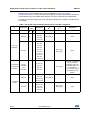
In this document, the SEooC is identified as the STM8AF microcontroller (MCU), references
as a functional block inserted in a system defined by the following Figure 1: Definition of the
STM8AF as a SEooC. The MCU acts as the processing unit of the system, acquiring field
data from sensors, processing according to the implemented algorithm and taking
10/59
DocID028066 Rev 1
UM1915
STM8AF Safety Architecture
decisions, sent to external actuators in the form of specific commands. The MCU is
connected directly or indirectly to sensors and actuators by communication busses.
Figure 1. Definition of the STM8AF as a SEooC
Other components might be connected to the SEooC, like the external HW components
needed to guarantee either the functionality of the STM8AF (external memory, clock quartz
etc.) or its safety (for example the external watchdog, voltage supervisors).
3.3
Assumed safety requirements
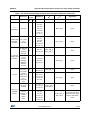
A SEooC is developed, according to ISO 2626-10 clause 9, on the basis of assumptions of
intended functionality, use and context, including external interfaces (Figure 2: Relationship
between assumptions and SEooC development).
Figure 2. Relationship between assumptions and SEooC development
The validity of the aforementioned assumptions is checked, in the context of the actual item,
after the integration of the SEooC.
In this document, it is assumed that the concept specification, the Hazard&Risk analysis,
the overall safety requirement specification and the consequent allocation, have determined
the assumed safety requirements reported in Table 2: List of STM8AF Assumed
Requirements:
DocID028066 Rev 1
11/59
58
STM8AF Safety Architecture
UM1915
Table 2. List of STM8AF Assumed Requirements
ID
Type
Assumed Requirement
AR01
Assumed
The SEooC is defined as the STM8A MCU playing a role of processing unit,
requirement as in Figure 1: Definition of the STM8AF as a SEooC
AR02
Failures in STM8AF HW part leading to wrong execution of the application
program and/or wrong data computations shall be mitigated to fulfil the ASILB
Assumed
capability, i.e.
requirement
single-point fault metric at the HW part level at least 90%
latent point fault metric at the HW part level at least 60%
AR03
Assumed
The STM8AF is assumed to be integrated in a product with a lifetime up to 10
requirement years
AR04
In accordance with ISO 26262-.5, 6.4.8 – Note 1, it is assumed that the
Assumed
MPFDI (Multiple-Point Fault Detection Interval) is equal to or lower than to the
requirement
item's “power-up to power-down” cycle (i.e. 1 hour).
AR05
Assumed
Safety Integrity Level required for the STM8AF is ASILB
requirement
AR06
Assumed
It is assumed a FTTI budget allocated to the STM8A of 250 msec(1)
requirement
AR07
It is assumed that the STM8AF implements a safe state defined as one in
which either:
the application software running on STM8AF MCU is informed of the
Assumed
(2)
requirement presence of a fault and a reaction is possible
or
if the application software cannot be informed, the MCU reset is executed(3)
AR08
Assumed
On the STM8AF SEooC ASIL, QM and/or not- safety related software(4)
requirement will be not executed together
1. FTTI value used for reference only. The end user shall verify that the FTTI value of the final application is
compatible with the requirements in terms of execution of periodical software-based test (refer to section
3.6).
2. The end user shall take into account that hardware random failures affecting the STM8AF can compromise
the MCU capability of operating properly (for example failure modes affecting the program counter, prevent
the correct execution of software).
3. According ISO 26262-1, the safe state is the operating mode of an item without unreasonable level of risk.
The ultimate definition of the safe state depends on the end user application.
4. The possibility for SEooC to execute ASIL, QM and non-safety-related functions together, has been
excluded because not supported by dedicated hardware.
3.3.1
The target safety metrics (ASIL, SPFM, LFM and PMHF)
According to the assumed requirement AR05 of the Table 2: List of STM8AF Assumed
Requirements), the target for the safety functions is ASILB; therefore every consideration
about absolute and relative safety metrics will take ASILB targets, as reported in Table 3:
Target safety metric values at the item level:
12/59
DocID028066 Rev 1
UM1915
STM8AF Safety Architecture
Table 3. Target safety metric values at the item level
Target value at
system level
Target value at
SEooC level
Metric type
Single-point fault metric (SPFM)
≥ 90%
≥ 90%
relative
Latent-fault metric (LFM)
≥ 60%
≥ 60%
relative
Probabilistic Metric for random Hardware
Failures (PMHF)
100 FIT
10 FIT
absolute
Safety metric defined
Despite safety metrics are defined at item level (i.e. at car level) for ISO 26262, the
functional safety standard explicitly foresees the computation of those metrics at a lower
level.
In this document, any claim and computation in terms of safety metrics will be done on the
activity safety scope, represented by the SEooC block diagram reported in Table 1:
Definition of the STM8AF as a SEooC.
The budget of the PMHF given to the SEooC should be, if possible, less than 10% of the
overall PMHF budget of the safety goal and therefore (for ASILB) the budget for the
STM8AF is 10%*100 FIT = 10 FIT.
3.3.2
The assumed target time intervals (FTTI and MPFDI)
As illustrated in ISO 26262-1:2001 - Figure 4 - Fault reaction time and fault tolerant time
interval, a system must be able to detect faults and move to safe state before a fault can
become a system level hazard.
In ISO 26262-1, the Fault Tolerant Time Interval (FTTI) is defined as the time-span in which
a fault, or faults, can be presented in a system before a hazardous event occurs.
Moreover, according to ISO 26262-1:2011, the Multiple-Point Fault Detection Interval
(MPFDI) is the time span to detect multiple-point fault before it can contribute to a multiplepoint failure.
From a system point of view, the STM8AF MCU is a safety-related element, to which it is
associated a portion of the FTTI system budget (see Figure 3: STM8AF FTTI allocation
and cycle time).
DocID028066 Rev 1
13/59
58
STM8AF Safety Architecture
UM1915
Figure 3. STM8AF FTTI allocation and cycle time
Therefore, according to the above figure, the portion of the FTTI assigned to a SEooC (in
this case the STM8A) strongly depends on the application.
In this document, according to ISO 26262-10, 9.2.3.3 d), it is assumed that any
implemented safety mechanisms related to the STM8A will complete its functions in less
than the assigned FTTI budget time reported in the AR06 of the Table 2: List of STM8AF
Assumed Requirements).
This value must be considered as a reference one and thus can be changed by the
MCU/system integrator, according to his own needs.
It is worth noting that according to ISO 26262-5, 7.4.3.3 a single point fault shall be detected
within the FTTI budget allocated to the component.
In this document, in accordance with ISO 26262-.5:2011, 6.4.8 – Note 1, it is assumed that
the MPFDI is equal to or lower than the “power-up to power-down” cycle of the item (i.e. one
driving cycle, see AR04 of the Table 2: List of STM8AF Assumed Requirements).
3.4
Electrical specifications and environment limits
The user must not exceed the electrical specification and the environmental limits defined in
the below list, as reported in the STM8AF user manual, in order to guarantee its own safety
integrity:
Absolute maximum rating
Capacity
Operating conditions
Due to the large number of STM8AF part numbers, the related user manuals/datasheets are
not listed in this document; users are responsible to carefully check the above reported
limits in the technical documentation on the related part number available on www.st.com.
14/59
DocID028066 Rev 1
UM1915
3.5
STM8AF Safety Architecture
Systematic safety integrity
Due to known device limitations for STM8AFxxxx automotive MCUs, the user must follow
the errata sheets (e.g. ES0143 for STM8AF6xxx and ES0144 for STM8AF5xxx series)
available on www.st.com, in order to avoid the introduction of systematic failures.
3.6
Safety mechanisms/measures
This section lists all the safety mechanisms/measures (hardware, software and application
level) considered in the safety analysis of the microcontrollers of the STM8AF series.
According to ISO 26262-1, “…a safety mechanism is a technical solution implemented by
Electrical/Electronic (E/E) functions or elements, or by other technologies, to detect faults
or control failures in order to achieve or maintain a safe state”.
It is expected that users are familiar with the STM8AF architecture, and that this document
is used in conjunction with the related device datasheet, user manual and reference
information. Therefore, in order to avoid any mistake and reduce the amount of information
to be shown, no functional details are included in this document.
Note that the part numbers of the STM8AF series represent different combinations of
peripherals (for instance, some of them are not equipped with CAN peripheral). To reduce
the number of documents and avoid information-less repetitions, the current safety manual
(and therefore this section) addresses the overall possible peripherals available in the
targeted part numbers. Users have to select which peripherals are really available on their
devices, and discard the meaningless recommendations accordingly.
The implementation guidelines reported in the following section are for reference purpose
only. Please, read the following definitions:
3.6.1
end user: the final user of STM8AF who is in charge of integrating the MCU in a real
application (for example an electronic control board).
application software: the real software that runs on the STM8AF and that is used to
implement the safety function.
STM8A CORE
Periodical core self-test software: CPU_SM_0
Permanent faults affecting the CPU are addressed through a dedicated software test,
executing a sequence of instructions and data transfers.
The software test is built around well-known techniques already addressed by
ISO 26262-5, D.2.3.1 (“Self-test by software: limited number of patterns (one channel)”).
The processing unit (CPU) is tested for functional correctness by applying at least one
pattern per instruction. The testing of the same class of instruction with multiple not-trivial
patterns, in order to involve each operand input and output bits, at least once equal to “0” e
once equal to “1”, is high recommended. The accumulation by means of not-trivial
computation (e.g. XOR) of the single instruction test result on the basis of the concept of
signature, is high recommended. The safety analysis of the CPU hardware has shown that a
stress-test for the pipeline structure is high recommended.
The overall test software suite is assumed to be periodically executed with a time period
compatible with the ISO 26262 requirements for the relationship between FTTI and the
diagnostic test interval (DTI).
DocID028066 Rev 1
15/59
58
STM8AF Safety Architecture
UM1915
Control flow monitoring in application software: CPU_SM_1
A significant part of the failure distribution of STM8A core for permanent faults is related to
failure modes directly related to program counter loss of control or hang-up. Due to their
intrinsic nature, such failure modes are not addressed by a standard software test method,
based on the execution of sequences of instruction/data access and consequent checks.
Therefore it is necessary to implement a run-time control of the application software flow, in
order to monitor and detect deviation from the expected behavior. Linking this mechanism to
watchdog firing, assures that severe loss of control (or, in the worst case, a program counter
hang-up) will be detected within DTI.
This diagnostic measure also contributes to the transient fault detection, affecting the
program counter and branch execution subpart in STM8A core.
The guidelines for the implementation of the method are the following:
The different internal states of the application software is well documented and
described (the use of a dynamic state transition graph is encouraged)
The monitoring of the correctness of each transition between different states of the
application software is implemented
The transition through all expected states during the normal application software
program loop is checked
The function in charge of triggering the system watchdog is implemented, in order to
constrain the triggering (preventing the watchdog reset) also to the correct execution of
the above-described method for program flow monitoring
The use of the window feature of the independent watchdog (IWDG) (or an external one)
helps to implement a more robust control flow mechanism fed by a different clock source. In
any case the safety metrics do not depend on the watchdog in use (the adoption of
independent or external watchdog contributes to the mitigation of dependent failures, see
Section 4.2.2: Clock).
Double computation in application software: CPU_SM_2
A timing redundancy for safety-related computation is considered to detect transient faults
affecting the STM8A subparts devoted to mathematical computations and data access.
The guidelines for the implementation of the method are the following:
The requirement needs to be applied only to safety-relevant computation, that is the
ones that could interfere with the system safety functions. Such computation needs to
be therefore carefully identified in the original application software source code
Both mathematical operation and comparison are intended as computation
The redundant computation for comparison could be implemented according to the
following template:
–
Original code:
If (VarA > VarB) then { ( execute function) }
–
Modified code:
copyVarA:=VarA; copyVarB:=VarB;
If (VarA > VarB) then {
If (copyVarA <= copyVarB) then { (signal_error);
break } ( execute function)
}
16/59
DocID028066 Rev 1
UM1915
STM8AF Safety Architecture
The redundant computation is implemented by using copies of the original data for
second computation, and by using an equivalent formula if possible
End users are responsible to carefully avoid that the optimization features of the
used compiler removes the timing redundancy introduced according to this current
condition of use
Stack hardening for application software: CPU_SM_3
The stack hardening method is required to address faults affecting the CPU register bank.
This method is based on source code modification, introducing information redundancy in
register-passed information to the called functions.
The guidelines for the implementation of the method are the following:
Pass also the redundant copy of the passed parameters values (possibly inverted) and
execute a coherence check in the function
Pass also the redundant copy of the passed pointers and execute a coherence check
in the function
For the parameters that are not protected by redundancy, it is recommended to implement
defensive programming techniques (plausibility check of passed values). For example
enumerated fields are to be checked for consistency.
Independent watchdog: CPU_SM_4
Using an external watchdog for the control flow monitoring method (CPU_SM_1)
contributes to further reduce potential common cause failures, because the external
watchdog will be clocked and supplied independently from the STM8AF.
3.6.2
Program FLASH memory
Periodical software test for Flash memory: FLASH_SM_0
Permanent faults affecting the system Flash memory (that is the memory cells and address
decoder) are addressed through a dedicated software test that checks the memory cell
contents versus the expected value, using signature-based techniques. The use of CRCbased encryption for signature is encouraged.
Without information about the frequency of usage of different occupied Flash sections, in
principle, all used Flash area is assumed to be tested with a time period compatible with the
ISO 26262 requirements for the relationship between FTTI and the diagnostic test interval
(DTI).
Control flow monitoring in application software: FLASH_SM_1
Permanent and transient faults affecting the system Flash memory (that is the memory cells
and address decoder) can interfere with the access operation by the CPU, leading to wrong
data or instruction fetches. Such wrong data and operation, if able to heavily interfere with
the expected flow of the application software, are detected by strong control flow
mechanism linked to a system watchdog. For more detailed implementation guidelines for
such technique refer to safety mechanism CPU_SM_1.
Note:
The implementation of the CPU_SM_1 automatically involves the FLASH_SM_1
implementation.
DocID028066 Rev 1
17/59
58
STM8AF Safety Architecture
3.6.3
UM1915
Data EEPROM memory
Information redundancy: EEP_SM_0
To address permanent faults affecting the internal EEPROM bank it is required to implement
information redundancy techniques. Possible techniques are:
use redundant copies of safety relevant data and perform coherence check before use
organize data in arrays and compute and check checksum field before use.
Due to their nature, data stored in EEPROM are typically managed directly by the end user
application software, therefore it is reasonable to rely on methods implemented in the final
software solution
Software read-back after write operation: EEP_SM_1
To address missing writes on EEPROM cells, it is required that the application software
executes a read-back of written data after an update of the EEPROM values. Missing writes
will be handled as a hardware fault.
3.6.4
RAM memory
Periodical software test for RAM memory: RAM_SM_0
To address permanent faults affecting RAM data cells and address decoder it is required to
execute a periodical software test on the system RAM memory. The selection of the
algorithm ensures the target coverage for both the RAM cells and the address decoder. The
end user provides also evidences of the effectiveness of the coverage of the selected
method.
The overall test software suite is assumed to be periodically executed with a time period
compatible with the ISO 26262 requirements for the relationship between FTTI and the
diagnostic test interval (DTI).
Stack hardening for application software: RAM_SM_1
The stack hardening method is used to enhance the application software robustness to
RAM faults affecting the address decoder. The method is based on source code
modification, introducing information redundancy in the stack-passed information to the
called functions. This method is relevant in case the combination between the final
application software structure and the compiler settings requires a significant use of the
stack for passing function parameters.
The guidelines for the implementation of the method are the following:
18/59
Pass also the redundant copy of the passed parameters values (possibly inverted) and
execute a coherence check in the function
Pass also the redundant copy of the passed pointers and execute a coherence check
in the function
For parameters that are not protected by redundancy, implement defensive
programming techniques such as the plausibility check of the passed values (for
example to check the consistency of enumerated fields)
DocID028066 Rev 1
UM1915
STM8AF Safety Architecture
Information redundancy for safety-related variables in application software:
RAM_SM_2
To address transient faults affecting RAM controller and RAM cells, it is required to
implement information redundancy of the safety-related system variables stored in the
RAM.
The guidelines for the implementation of this method are the following:
The system variables that are safety-related (in the sense that a wrong value read in
the RAM affects the safety functions) are well-identified and documented.
The arithmetic computation and/or decision based on such variables are/is executed
twice and the two final results are compared
Non-numeric variables uses enumerated-type constant values for coding, avoiding
trivial patterns (all-0x00 or all-0xFF); application software checks for consistence the
value assumed by the variables, when used
Numeric variables are grouped and protected by means of a checksum (for instance,
computed by XOR), updated each variable overwriting and checked at least once per
FTTI
Note that the implementation of this safety method shows a partial overlap with an already
planned method for STM8A core (CPU_SM_1); optimizations in implementing both methods
are therefore possible (see the description of the CPU_SM_1 in section Control flow
monitoring in application software: CPU_SM_1).
3.6.5
Boot ROM
Control flow monitoring in application software: ROM_SM_0
The boot loader starts executing after reset. Permanent and transient faults affecting the
boot ROM memory can leads to wrong execution of the application software at the end of
the boot procedure. Such alteration is detected by a strong control flow mechanism linked to
a system watchdog. For more detailed implementation guidelines for such technique refer to
safety mechanism CPU_SM_1.
Note:
The implementation of the CPU_SM_1 automatically involves the ROM_SM_0
implementation.
3.6.6
Basic enhanced CAN (beCAN)
Periodical read-back of configuration registers: CAN_SM_0
This diagnostic measure that is typically referred to as “Read Back Periodic by Software of
Configuration Registers” executes a periodical check of the configuration registers of
beCAN peripheral respect to its expected value that is previously stored in the RAM and
adequately updated after each configuration change. It mainly addresses the transient faults
affecting the configuration registers, detecting bit flips. The register test is executed at least
once per DTI in order to be able to claim the related diagnostic coverage.
Protocol error signals: CAN_SM_1
The CAN protocol error counters, which are entirely managed by the module at hardware
level despite being conceived to detect network-related abnormal conditions, are able to
contribute to the detection of the faults leading to error messages generation.
DocID028066 Rev 1
19/59
58
STM8AF Safety Architecture
UM1915
Handling such error signals at application level of is a common technique in embedded
applications.
Information redundancy techniques on messages, including End to End
safing: CAN_SM_2
The CAN communications are protected by addressing both the permanent and transient
faults with the redundant information technique that includes the End to End safing.
For the implementation of redundant information, it is possible to adopt a different approach:
Multiple sending of the same message, with comparison of the received results.
Addition by the sender of a checksum field to the message to be verified by the
receiver.
In case the checksum field approach is adopted, the selection of the algorithm for checksum
computation will ensure a similar protection against message corruption as the one ensured
by a full redundancy.
For End to End safing, additional measures are implemented:
Additional field in payload allowing the unique identification of sender/receiver, and
coherence check by receiver side
Timing monitoring of the message exchange (for example check the message arrival
within the expected time window)
Check of the message consistence using a message counter in the additional payload
field and checking the right sequence of messages on the receiver side
The use of a safe communication protocol such as PROFIsafe is recommended for the
correct implementation of this safety mechanism.
3.6.7
LINUART
Periodical read-back of configuration registers: LINUART_SM_0
This diagnostic measure that is typically referred to as “Read Back Periodic by Software of
Configuration Registers” executes a periodical check of the configuration registers of
LINUART respect to their expected value (previously stored in RAM and adequately
updated after each configuration change). It mainly addresses transient faults affecting the
configuration registers, detecting bit flips. The registers test is executed at least once per
DTI.
Protocol error Signal: LINUART_SM_1
The LIN protocol errors signals (if used) despite being conceived to detect physical layer
related abnormal conditions, are able to contribute to the detection to faults leading to error
messages generation. For instance, option parity bit in data byte frame, overrun error.
Handling such error signals at application level is a common technique in embedded
applications.
20/59
DocID028066 Rev 1
UM1915
STM8AF Safety Architecture
Information redundancy techniques on messages: LINUART_SM_2
The redundant information technique is used to protect the LIN/UART communications by
detecting both the permanent and transient faults. There are two different approaches to
implement this technique:
Multiple sending of the same message, with comparison of the received results
Addition by the sender of a checksum field to the message to be verified by the
receiver
In case the checksum field approach is adopted, the selection of the algorithm for checksum
computation will ensure a similar protection against message corruption as the one ensured
by a full redundancy. Theoretical demonstrations on coverage capability are admitted – the
use of CRC coding is anyway suggested.
The above-reported approaches are equivalent; an additional criterion for the selection of
the approach is the availability of a quick hardware support on the MCU platform, and the
evaluation of the computation capability of the external device exchanging data with
STM8AF.
3.6.8
USART
Periodical read-back of configuration registers: UART_SM_0
This diagnostic measure that is typically referred to as “Read Back Periodic by Software of
Configuration Registers” executes a periodical check of the configuration registers of
USART respect to their expected value (previously stored in RAM and adequately updated
after each configuration change). It mainly addresses transient faults affecting the
configuration registers, detecting bit flips. The registers test is executed at least once per
DTI.
Protocol error signals: UART_SM_1
The UART protocol errors signals (if used) despite being conceived to detect physical layer
related abnormal conditions, are able to contribute to the detection of faults leading to error
messages generation. For instance, option parity bit in data byte frame, overrun error.
Handling such error signals at application level is a common technique in embedded
applications.
Information redundancy techniques on messages: UART_SM_2
The redundant information technique is used to protect the USART communications by
detecting both the permanent and transient faults. There are two different approaches to
implement this technique:
Multiple sending of the same message, with comparison of the received results
Addition by the sender of a checksum field to the message to be verified by the
receiver
In case the checksum field approach is adopted, the selection of the algorithm for checksum
computation will ensure a similar protection against message corruption as the one ensured
by a full redundancy. Theoretical demonstrations on coverage capability are admitted – the
use of CRC coding is anyway suggested.
The above-reported approaches are equivalent; an additional criterion for the selection of
the approach is the availability of a quick hardware support on the MCU platform, and the
DocID028066 Rev 1
21/59
58
STM8AF Safety Architecture
UM1915
evaluation of the computation capability of the external device exchanging data with
STM8AF.
3.6.9
I2C
Periodical read-back of configuration registers: IIC_SM_0
This diagnostic measure that is typically referred to as “Read Back Periodic by Software of
Configuration Registers” executes a periodical check of the configuration registers of I2C
respect to their expected value (previously stored in RAM and adequately updated after
each configuration change). It mainly addresses transient faults affecting the configuration
registers, detecting bit flips. The registers test is executed at least once per DTI.
Protocol error signals: IIC_SM_1
The I2C protocol errors signals, despite being conceived to detect physical layer related
abnormal conditions, are able to contribute to the detection of faults leading to error
messages generation such as for instance the ACK assertion phase, and related checks.
Handling such error signals at application level is a common technique in embedded
applications.
Information redundancy techniques on messages: IIC_SM_2
The redundant information technique is used to protect the I2C communications by
detecting both the permanent and transient faults. There are two different approaches to
implement this method:
Multiple sending of the same message, with comparison of the received results
Addition by the sender of a checksum field to the message to be verified by the
receiver
In case the checksum field approach is adopted, the selection of the algorithm for checksum
computation will ensure a similar protection against message corruption as the one ensured
by a full redundancy. Theoretical demonstrations on coverage capability are admitted – the
use of CRC coding is anyway suggested (also looking for the availability of a quick
hardware support on the MCU platform).
The above-reported approaches are equivalent; an additional criterion for the selection is
the evaluation of the computation capability of the external device exchanging data with
STM8AF.
3.6.10
SPI
Periodical read-back of configuration registers: SPI_SM_0
This diagnostic measure that is typically referred to as “Read Back Periodic by Software of
Configuration Registers” executes a periodical check of the configuration registers of SPI
respect to their expected values previously stored in RAM and adequately updated after
each configuration change. It mainly addresses transient faults affecting the configuration
registers, detecting bit flips. The registers test is executed at least once per DTI.
Protocol error signals: SPI_SM_1
The SPI protocol errors signals, despite being conceived to detect physical layer related
abnormal conditions, are able to contribute to the detection to faults leading to error
messages generation such as, for instance, FIFO overrun and Mode error flags.
22/59
DocID028066 Rev 1
UM1915
STM8AF Safety Architecture
Handling such error signals at application level is a common technique in embedded
applications.
Information redundancy techniques on messages: SPI_SM_2
The redundant information technique is used to protect the SPI communications by
detecting both the permanent and transient faults. There are two different approaches to
implement this method:
Multiple sending of the same message, with comparison of the received results
Addition by the sender of a checksum field to the message to be verified by the
receiver
In case the checksum field approach is adopted, the selection of the algorithm for checksum
computation will ensure a similar protection against message corruption as the one ensured
by a full redundancy. Theoretical demonstrations on coverage capability are admitted – the
use of the hardware CRC computation unit built into SPI module is highly suggested.
The above-reported approaches are equivalent; an additional criterion for the selection is
the evaluation of the computation capability of the external device exchanging data with
STM8AF.
3.6.11
Analog to Digital Converter (ADC)
Periodical read-back of configuration registers: ADC_SM_0
This diagnostic measure that is typically referred to as “Read Back Periodic by Software of
Configuration Registers” executes a periodical check of the configuration registers of ADC
respect to their expected values, previously stored in RAM and adequately updated after
each configuration change. It mainly addresses transient faults affecting the configuration
registers, detecting bit flips. The registers test is executed at least once per DTI.
Multiple acquisitions by application software: ADC_SM_1
To address the transient faults that affect the ADC module, it is required to implement a
timing information redundancy scheme that executes multiple acquisitions of the same
signal. This recommendation will most probably be satisfied by the end user application
software. The usage of multiple acquisitions followed by average operations is a common
technique in industrial applications where it is needed to survive with spurious EMI disturbs
on sensor lines.
Range check by application software: ADC_SM_2
To address permanent faults affecting ADC module, and also to address failure modes
affecting the analogue section, it is required that the application software executes a range
/plausibility checks on the measures coming from ADC acquisitions. The guidelines for the
implementation of the method are the following:
The expected data range to be acquired is investigated and adequately documented.
Note that in a well-designed application it is unlikely that during normal operation an
input signal has a value very close to or over the upper and below the lower rail limit
(saturation in signal acquisition).
If the application software is aware of the state of the system, this information has to be
used in the range check implementation. For example, if the ADC value is the
measurement of a current through a power load, reading an abnormal value (for
DocID028066 Rev 1
23/59
58
STM8AF Safety Architecture
UM1915
instance a current flowing in opposite direction versus the load supply) may indicate a
fault in the acquisition module.
Note:
As the ADC module is shared between different possible external sources, the
combination of plausibility checks on the different signals acquired helps to cover the
whole input range in a very efficient way.
The implementation of this safety mechanism is strongly application-dependent.
Periodical software test for ADC: ADC_SM_3
To address permanent faults affecting ADC module, and also to address failure modes
affecting the analogue section, it is required to execute a periodical test on the ADC
acquisition section. The method is implemented by acquiring either the internal reference
voltage or, alternatively, a reference voltage coming from the external (board) and
connected to an input pin, and comparing to the expected value. This test is executed
periodically at least once per DTI.
Advanced control and General Purpose timers (TIM 1 and TIM 2/3)
As the advanced control and general purpose timers are equipped with different channels,
each independent from the others, and possibly programmed to realize different features,
the safety mechanism is selected individually for each channel.
Periodical read-back of configuration registers: TIM_SM_0
This diagnostic measure that is typically referred to as “Read Back Periodic by Software of
Configuration Registers” executes a periodical check of the configuration registers of
TIMER respect to their expected values,previously stored in RAM and adequately updated
after each configuration change. It mainly addresses transient faults affecting the
configuration registers, detecting bit flips. The registers test is executed at least once per
DTI.
Dual channel redundancy for counting timers: TIM_SM_1
This method provides a high level of coverage for both permanent and transient faults on
the addressed timers. The method is conceived to protect the timers with counting features,
for example the timers dedicated to maintain a system time base and/or to generate a timed
interrupt for the execution of service routines (like for instance general timing counters
update/increase).
The guidelines for the implementation of the method are the following:
In case of timer used as a time base, use one of the timers as time-base source in the
application software, and the other one just for check. In that case the coherence check
for the dual channel redundancy will be done at application level
In case of interrupt generation usage, use the first timer as main interrupt source for the
service routines, and use the second timer to activate a “checking routine” that crosschecks the coherence between the timers
Dual channel redundancy for input capture timers: TIM_SM_2
This method, based on dual channel redundancy scheme, provides a high level of coverage
for both the permanent and transient faults on the addressed timers. It is conceived to
protect the timers used for external signal acquisition and measurement, like “input capture”
and “encoder reading”. The implementation is easy as it simply requires connecting the
external signals also to the redundant timer, and performs a coherence check on the
24/59
DocID028066 Rev 1
UM1915
STM8AF Safety Architecture
measured data at application level. To reduce the potential effect of the common cause
failure, it is suggested, for redundancy, to use a channel belonging to a different timer
module and mapped to not-adjacent pins on the device package.
Loopback scheme for PWM outputs: TIM_SM_3
This method uses a loopback scheme to detect permanent and transient faults on the timer
channels used for output waveform generations (output compare, PWM and one-pulse
mode). It is implemented by connecting the output signal to a separate channel, either in the
same or in another timer, to acquire the generated waveform characteristics.The guidelines
for the implementation of the method for the PWM signal are the following:
Both frequency and duty cycle of PWM are measured and checked versus the
expected value
To reduce the potential effect of common cause failure, it is suggested to use for the
loopback check a channel belonging to a different timer module and mapped to notadjacent pins on the device package
This measure can be replaced, under the end-user responsibility, by different loopback
schemes already in place in the final application and rated as equivalent. For example, if
the PWM is used to drive an external power load, the measurement of the on-line current
value can be used instead of the PWM frequency one.
3.6.12
Basic timer (TIM 4)
Periodical read-back of configuration registers: BTIM_SM_0
This diagnostic measure that is typically referred to as “Read Back Periodic by Software of
Configuration Registers” executes a periodical check of the configuration registers of
TIMER respect to their expected values, previously stored in RAM and adequately updated
after each configuration change. It mainly addresses transient faults affecting the
configuration registers, detecting bit flips. The registers test is executed at least once per
DTI.
Dual channel redundancy for counting timers: BTIM_SM_1
This method provides a high level of coverage for both permanent and transient faults on
the addressed timers. The method is conceived to protect the timers with counting features,
for example the timers dedicated to maintain a system time base and/or to generate a timed
interrupt for the execution of service routines (like for instance general timing counters
update/increase).
The guidelines for the implementation of the method are the following:
In case of timer used as a time base, use one of the timers as time-base source in the
application software, and the other one just for check. In that case the coherence check
for the dual channel redundancy will be done at application level
In case of interrupt generation usage, use the first timer as main interrupt source for the
service routines, and use the second timer to activate a “checking routine” that crosschecks the coherence between the timers
DocID028066 Rev 1
25/59
58
STM8AF Safety Architecture
3.6.13
UM1915
GPIO – PORT A/B/C/D/E/F/G/H
Periodical read-back of configuration registers: GPIO_SM_0
This diagnostic measure that is typically referred to as “Read Back Periodic by Software of
Configuration Registers” executes a periodical check of the configuration registers of GPIO
respect to their expected values, previously stored in RAM and adequately updated after
each configuration change. It mainly addresses transient faults affecting the configuration
registers, detecting bit flips. The registers test is executed at least once per DTI.
Dual channel redundancy for input GPIO lines: GPIO_SM_1
To address both permanent and transient faults on GPIO lines used as input, it is required to
implement a dual channel redundancy scheme by connecting the external safety-relevant
signal to two independent GPIO lines. To reduce the potential impact of common cause
failure, it is suggested to use GPIO lines belonging to different I/O ports (for example PORT
A and B) and mapped to not-adjacent pins on the device package.
Loopback configuration for output GPIO lines: GPIO_SM_2
To address both permanent and transient faults on GPIO lines used as output, it is required
to implement a loopback scheme, connecting the output to a different GPIO line
programmed as input and used to check the expected value on output port. To reduce the
potential impact of common cause failure, it is suggested to use GPIO lines belonging to
different I/O ports (for example PORT A and B) and mapped to not-adjacent pins on the
device package.
3.6.14
Address and Data bus
Periodical software test for interconnections: BUS_SM_0
The intra-chip connection resources need to be periodically tested for permanent faults
detection. Note that STM8AF MCUs have no hardware safety mechanism to protect these
structures. The test executes a connectivity test of these shared resources, including the
testing of the arbitration mechanisms between peripherals. This method, based on the
periodical execution of software-based tests is executed at least once per DTI.
Note that the implementation of this safety method is overlapped by already planned
methods for the configuration register checks for the STM8A peripherals (e.g. CAN_SM_0).
Implementation of all such methods is equivalent to the implementation of BUS_SM_0.
Information redundancy in intra-chip data exchanges: BUS_SM_1
Both permanent and transient faults affecting the intra-chip connection features are
addressed by information redundancy techniques implemented on the messages
exchanged inside the MCU.
Note that the implementation of this safety method is overlapped by already planned
methods related to information redundancy for the STM8A peripherals (e.g. CAN_SM_2).
Implementation of all such methods is equivalent to the implementation of BUS_SM_1.
26/59
DocID028066 Rev 1
UM1915
3.6.15
STM8AF Safety Architecture
Supply voltage system
Periodical read-back of configuration registers: VSUP_SM_0
This diagnostic measure that is typically referred to as “Read Back Periodic by Software of
Configuration Registers” executes a periodical check of the configuration registers of the
Power Control logic respect to their expected values, previously stored in RAM and
adequately updated after each configuration change. It mainly addresses transient faults
affecting the configuration registers, detecting bit flips. The registers test is executed at least
once per DTI.
Supply Voltage Monitoring: VSUP_SM_1
It is required to detect early the under voltage and overvoltage conditions that are potential
sources of failure at MCU level. The power supply values close to the operating limits
reported in device datasheet are considered at the same level as hardware faults and lead
to similar recovery actions by the application software.
The usage of an external monitoring power supply device outside the MCU can ensure the
protection against potential common cause failures.
Warning:
In order to reduce the risk of an overvoltage condition, it is
highly recommended to respect the absolute maximum
ratings for voltage (see Section 3.4: Electrical specifications
and environment limits).
Independent watchdog: VSUP_SM_2
The independent watchdog is fed directly by V DD; therefore, major failures in the 1.8 V
supply for digital logic (core/peripherals) will not affect its behavior but may lead to a
violation of the IWDG window for the key value writing by the application software, leading
to a system reset.
3.6.16
Reset and Clock control subsystems
Periodical read-back of configuration registers: CLK_SM_0
This diagnostic measure that is typically referred to as “Read Back Periodic by Software of
Configuration Registers” executes a periodical check of the configuration registers of the
Reset and Clock Control logic respect to their expected values (previously stored in RAM
and adequately updated after each configuration change). It mainly addresses transient
faults affecting the configuration registers, detecting bit flips. The registers test is executed
at least once per DTI.
Clock Security System (CSS): CLK_SM_1
The Clock Security System (CSS) detects the loss of HSE and LSE clock activity and
executes the corresponding recovery action, e.g. switch-off HSE and commute on the HSI.
For this reason it is able to detect potential abnormal situations:
Loss of external clock,
Abnormal activation of HSE (or LSE) despite being disabled by design.
DocID028066 Rev 1
27/59
58
STM8AF Safety Architecture
UM1915
The CSS detection of abnormal condition is considered as equivalent to hardware faults and
brings to similar recovery actions by the application software.
Independent watchdog: CLK_SM_2
The independent watchdog is fed by a dedicated oscillator; therefore, major failures on
clock generation at system level will not affect its behavior but may lead to a violation of the
IWDG window for the key value write by the application software, leading to a system reset.
Note that the efficiency of this safety mechanism is strongly dependent on the correct
window setting and handling for the IWDG. The refresh of the IWDG should be implemented
in order to bring alteration of the program flow able to bypass the time window limit.
3.6.17
Auto-wakeup timer (AWU)
The AWU is used to provide an internal wakeup time base that is used when the MCU goes
into Active-halt power saving mode.
Periodical read-back of configuration registers: AWU _SM_0
This diagnostic measure that is typically referred to as “Read Back Periodic by Software of
Configuration Registers” executes a periodical check of the configuration registers of the
watchdogs respect to their expected values (previously stored in RAM and adequately
updated after each configuration change). It mainly addresses transient faults affecting the
configuration registers, detecting bit flips. The registers test is executed at least once per
DTI.
Software test for auto-wakeup timer at startup: AWU _SM_1
This safety mechanism ensures the right functionality of the auto-wakeup timer. At startup,
the software test programs the auto-wakeup timer with the required time interval, stores a
specific flag in the RAM and waits for the reset signal. After the wake-up, the software
understands that the AWU has correctly triggered, and does not execute the procedure
again. This method has to be applied only in case the implemented safety goal will plan the
use of the auto-wakeup feature.
3.6.18
Watchdogs (IWDG, WWDG)
Periodical read-back of configuration registers: WDG_SM_0
This diagnostic measure that is typically referred to as “Read Back Periodic by Software of
Configuration Registers” executes a periodical check of the configuration registers of the
watchdogs respect to their expected values (previously stored in RAM and adequately
updated after each configuration change). It mainly addresses transient faults affecting the
configuration registers, detecting bit flips. The registers test is executed at least once per
DTI.
Software test for watchdog at startup: WDG_SM_1
This safety mechanism ensures the right functionality of the internal watchdogs in use. At
startup, the software test programs the watchdog with the required expiration timeout,
stores a specific flag in the RAM and waits for the reset signal. After the watchdog reset, the
software understands that the watchdog has correctly triggered, and does not execute the
procedure again.
28/59
DocID028066 Rev 1
UM1915
3.6.19
STM8AF Safety Architecture
Debug/ SWIM (single wire interface module)
Independent watchdog: DBG_SM_0
The debug unintentional activation due to hardware random fault will result in the massive
disturbance of the independent watchdog or alternately, the other system watchdog WWDG
or an external one.
3.6.20
Interrupt controller (NVIC and EXTI)
Periodical read-back of configuration registers: INTC _SM_0
This diagnostic measure that is typically referred to as “Read Back Periodic by Software of
Configuration Registers” is implemented by executing a periodical check of the
configuration registers of each used system peripheral respect to its expected value,
previously stored in RAM and adequately updated after each configuration change. It
mainly addresses the transient faults that affect the configuration registers, by detecting bit
flips. The register test is executed at least once per DTI.
Expected and unexpected interrupt check: INTC_SM_1
According to ISO 26262-5 Table D.1 recommendations, a safety mechanism/measure for
incorrect interrupt executions and for omission of or continuous interrupts must be
implemented. The method of expected and unexpected interrupt check is implemented at
application software level. It contributes to detect both permanent and transient fault for all
the above-reported failure modes affecting interrupt handling.
The guidelines for the implementation of the method are the following:
3.6.21
The list of the implemented interrupt for the MCU is well documented, reporting also
the expected frequency of each request when possible (for example the interrupts
related to ADC conversion completion, therefore coming on a deterministic way)
Individual counters are maintained for each served interrupt request, in order to detect
in a given time frame the cases of a) no interrupt at all b) too many interrupt requests
(“babbling idiot” interrupt source). The control of the time frame duration shall be
regulated according to the individual interrupt expected frequency
Interrupt vectors related to unused interrupt source point to a default handler that will
report, in case of triggering, a faulty condition (unexpected interrupt)
In case an interrupt service routine is shared between different sources, a plausibility
check on the caller identity is implemented
Interrupt requests related to not-safety-relevant peripherals are handled with the same
method here described, despite their originator safety classification; in order to
decrease the complexity of this method implementation, the use of polling instead of
interrupt for not-safety-relevant peripherals is suggested
Latent fault detection
ISO 26262 considers also a metric for “latent” faults. The latent fault is a multiple-point fault
which presence is not detected by a safety mechanism nor perceived by the driver within
the multiple-point fault detection interval. In practical words, the latent fault is a combination
of a fault in a safety mechanism - that by itself will NOT cause the violation of the safety goal
(function) - and a fault in the mission logic supervised by that safety mechanism.
DocID028066 Rev 1
29/59
58
STM8AF Safety Architecture
UM1915
The following reported methods mainly address latent fault for the planned safety
mechanism at MCU level.
Independent Watchdog: LAT_SM_0
Each safety mechanism implemented as periodical software testing runs on the CPU.
Possible faults in the safety mechanism are therefore faults in the “support” for the
execution that is the CPU. The independent watchdog is considered here as safety
mechanism addressing the program counter failures due to the CPU hardware random
faults.
Periodical core self-test software: LAT_SM_1
As the major part of the safety mechanism described in this safety manual is implemented
by software, the periodical core self-test software execution able to detect faults in the
STM8 CPU acts as safety mechanism for latent faults. For implementation details refer to
the description of CPU_SM_0 safety mechanism.
3.6.22
Disable and periodic cross-check of unintentional activation of unused
peripherals
This section reports the safety mechanism that addresses peripherals not used by the
safety application, or not used at all.
Unused peripherals disable: FFI_SM_0
This method contributes to the reduction of the probability of cross-interferences caused by
peripherals not used by the software application. It is implemented by end users, taking care
of disabling by software (for instance during the system boot) each peripheral that is not
used.
Periodical read-back of interference avoidance registers: FFI_SM_1
This method contributes to the reduction of the probability of cross-interferences between
peripherals that can potentially conflict on the same output pins, including for instance
unused peripherals (refer to FFI_SM_0). This diagnostic measure executes a periodical
check of the below described registers respect to their expected values (previously stored in
RAM and adequately updated after each configuration change). The register test is
executed at least once per DTI.
The configuration registers to be tested with this method are those related to clock disabling
features for peripherals and those related to the enabling of alternate functions on I/O pins.
3.7
Assumption of Use (AoU)
This section describes the Assumptions of Use (AoU) of the STM8AF that the MCU/system
integrator will consider (together with the requirements listed in Table 2: List of STM8AF
Assumed Requirements) with respect to its intended use.
The AoUs are different from the HW safety requirements of STM8AF. The AoUs are
requirements for the MCU/system integrator.
30/59
DocID028066 Rev 1
UM1915
3.7.1
STM8AF Safety Architecture
List of Assumptions of Use (AoU)
The following tables summarize the Assumptions of Use (AoU) to be fulfilled by users of the
STM8AF MCUs.
The results shown in the following Table 4: Safety Analysis Results are valid under the
condition that the AoU, described herein, and the assumed requirements listed in Table 2:
List of STM8AF Assumed Requirements, are fulfilled by the STM8AF MCU/system
integrator.
The following table lists the assumptions of use and for each of them shows the degree of
recommendation using the typical ISO 26262 coding in order to keep the text consistent with
the standard and to facilitate their interpretation by the user. For each AoU, the degree of
recommendation to use the corresponding method depends on the ASIL and is categorized
as follows:
“++” indicates that the assumption is highly recommended for the identified ASIL
“+” indicates that the assumption is recommended for the identified ASIL
“o” indicates that the assumption has no recommendation for or against its usage for
the identified ASIL
Table 4: List of safety mechanisms provides a summary of the safety concept
recommendations reported in Section 3.6: Safety mechanisms/measures.
The assumptions of use to be applied to STM8AF MCUs are reported in the form of safety
mechanism (SM) requirements.
The “X” marker in the “Perm” and “Trans” columns of the Table 4: List of safety mechanisms
indicates that the related safety mechanism is effective for such fault model.
Table 4. List of safety mechanisms
STM8AF
function
STM8 CORE
Program FLASH
memory
Data EEPROM
Diagnostic
Description
ASIL B
Perm
Trans
CPU_SM_0
Periodical core self-test software
++
X
-
CPU_SM_1
Control flow monitoring in application
software
++
X
X
CPU_SM_2
Double computation in application
software
++
-
X
CPU_SM_3
Stack hardening for application software
+
X
X
CPU_SM_4
Independent watchdog
o
X
X
FLASH_SM_0
Periodical software test for Flash
memory
++
X
-
FLASH_SM_1
Control flow monitoring in application
software
+
X
X
FLASH_SM_3
Option byte write protection
M
-
-
EEP_SM_0
Information redundancy
++
X
-
EEP_SM_1
Software read-back after write operation
+
X
X
DocID028066 Rev 1
31/59
58
STM8AF Safety Architecture
UM1915
Table 4. List of safety mechanisms (continued)
STM8AF
function
RAM Memory
Boot ROM
beCAN
LINUART
UART
I2C
SPI
ADC
32/59
Diagnostic
Description
ASIL B
Perm
Trans
RAM_SM_0
Periodical software test for RAM
memory
++
X
-
RAM_SM_1
Stack hardening for application software
+
X
X
RAM_SM_2
Information redundancy for system variables
in application software
++
X
X
ROM_SM_0
Control flow monitoring in application
software
++
X
-
CAN_SM_0
Periodical read-back of configuration
registers
++
X
X
CAN_SM_1
Protocol error signals
+
X
X
CAN_SM_2
Information redundancy techniques on
messages, including End to End safing
++
X
X
LINUART_SM_0
Periodical read-back of configuration
registers
++
X
-
LINUART_SM_1
Protocol error signals
+
X
X
LINUART_SM_2
Information redundancy techniques on
messages
++
X
X
UART_SM_0
Periodical read-back of configuration
registers
++
X
X
UART_SM_1
Protocol error signals
+
X
X
UART_SM_2
Information redundancy techniques on
messages
++
X
X
IIC_SM_0
Periodical read-back of configuration
registers
++
X
X
IIC_SM_1
Protocol error signals
+
X
X
IIC_SM_2
Information redundancy techniques on
messages
++
X
X
SPI_SM_0
Periodical read-back of configuration
registers
++
X
X
SPI_SM_1
Protocol error signals
+
X
X
SPI_SM_2
Information redundancy techniques on
messages
++
X
X
ADC_SM_0
Periodical read-back of configuration
registers
++
X
X
ADC_SM_1
Multiple acquisition by application
software
++
-
X
ADC_SM_2
Range check by application software
++
X
X
ADC_SM_3
Periodical software test for ADC
+
X
-
DocID028066 Rev 1
UM1915
STM8AF Safety Architecture
Table 4. List of safety mechanisms (continued)
STM8AF
function
TIM1 and TIM2/3
TIM4
GPIO
Addressand Data
bus
Supply voltage
system
Clock and Reset
Diagnostic
Description
ASIL B
Perm
Trans
TIM_SM_0
Periodical read-back of configuration
registers
++
X
X
TIM_SM_1
Dual channel redundancy for counting timers
++
X
X
TIM_SM_2
Dual channel redundancy for input capture
timers
++
X
X
TIM_SM_3
Loopback scheme for PWM outputs
++
X
X
BTIM_SM_0
Periodical read-back of configuration
registers
++
X
X
BTIM_SM_1
Dual channel redundancy for counting timers
++
X
X
GPIO_SM_0
Periodical read-back of configuration
registers
++
X
X
GPIO_SM_1
Dual channel redundancy for input GPIO
lines
++
X
X
GPIO_SM_2
Loopback scheme for output GPIO lines
++
X
X
GPIO_SM_3
GPIO port configuration lock register
+
-
-
BUS_SM_0
Periodical software for interconnections
++
X
-
BUS_SM_1
Information redundancy in intra-chip data
exchanges
++
X
X
VSUP_SM_0
Periodical read-back of configuration
registers
++
X
X
VSUP_SM_1
Supply voltage monitoring
++
X
-
VSUP_SM_2
Independent Watchdog
++
X
-
CLK_SM_0
Periodical read-back of configuration
registers
++
X
X
CLK_SM_1
CSS Clock Security System
++
X
-
CLK_SM_2
Independent Watchdog
++
X
-
CLK_SM_3
Internal clock cross-measure
+
X
-
WAU_SM_0
Periodical read-back of configuration
registers
++
X
X
WAU_SM_1
Software test for auto-wakeup timer at
startup
+
X
X
WDG_SM_0
Periodical read-back of configuration
registers
++
X
X
WDG_SM_1
Software test for watchdog at startup
o
X
-
DBG_SM_0
Independent watchdog
++
X
X
WAURTC
Windows WDG
and IWDG
Debug
DocID028066 Rev 1
33/59
58
STM8AF Safety Architecture
UM1915
Table 4. List of safety mechanisms (continued)
STM8AF
function
Interrupt
controller
Software- based
safety
mechanism
Part separation
(no interference)
Diagnostic
Description
ASIL B
Perm
Trans
INTC_SM_0
Periodical read-back of configuration
registers
++
X
X
INTC_SM_1
Expected and unexpected interrupt check
by application software
++
X
X
LAT_SM_0
Independent Watchdog
+
X
-
LAT_SM_1
Periodical core self-test software
+
X
-
FFI_SM_0
Unused peripherals disable
++
-
-
FFI_SM_1
Periodical read-back of interference
avoidance registers
++
-
-
The above-described safety mechanism/measures are implemented with different levels of
abstraction depending on their nature: the more a safety mechanism is implemented as
application-independent, the wider is its possible use on a large range of end-user
applications.
34/59
DocID028066 Rev 1
UM1915
4
Safety Analysis Results
Safety Analysis Results
This section reports the results of the safety analysis of the STM8AF MCU, according to ISO
26262 (in particular ISO 26262-10 Annex A) and following to the YOGITECH
fRMethodology flow, related to the hardware random and dependent failures.
ISO 26262-10 Annex A is a guideline about how to perform a safety analysis of a
microcontroller according to ISO 26262.
Briefly, the ISO 26262 has three main objectives:
To improve functional safety by reducing the HW random failures, i.e. failures that can
occur unpredictably during the lifetime of a hardware element and that follow a
probability distribution. They are quantified using safety “metrics”, as described in
Section 3.3.1: The target safety metrics (ASIL, SPFM, LFM and PMHF)
To improve functional safety by reducing or avoiding dependent failures, i.e. failures
whose probability of simultaneous or successive occurrence cannot be expressed
simply as the product of the unconditional probability of each failure. They include
common cause failures and cascading failures. They are analyzed in a qualitative way
by means of checklists, as described in Section 4.2: Dependent failures analysis
To reduce or avoid the systematic failures, i.e. failures, related in a deterministic way
to a certain cause, that can only be eliminated by a change of the design or of the
manufacturing process, operational procedures, documentation or other relevant
factors
As mentioned before, the target for the safety functions is ASILB; therefore every
consideration about absolute and relative safety metrics will take ASILB targets.
It is worth to recap here that ASILB report as target limits 90% for SPF (overall system and,
according fRMethodology approach, for both permanent and transient faults computed
separately) and 100 FIT for PMHF (100 FIT is indeed the overall budget available for the
system, therefore for STM8AF the allocated budget will be lower).
4.1
Hardware random failure analysis
The analysis for random hardware failures of STM8AF devices reported in this safety
manual is executed according to ISO 26262 and following the YOGITECH fRMethodology
flow.
The STM8AF has been divided into parts and sub-parts according the fRMethodology
approach and the procedure defined in ISO 26262-10. Then, for each part and subpart, the failure modes have been identified starting from the ones specified by ISO
26262-5, Annex D and then significantly extended based on detailed analyses
Each failure mode has been analyzed in terms of its “end effect” at the STM8AF I/O level.
Detailed results of the qualitative analysis are reported in the Annex 2. “STM8AF FMEDA
snapshot”
The main advantages of this flow are described in details in Appendix A. Overview of
fRMethodology.
About safety metrics, both relative (SPFM, LFM) and absolute (PMHF) have been
computed. The results are not reported in this section but in the Annex 2. “STM8AF
FMEDA snapshot”.
DocID028066 Rev 1
35/59
58
Safety Analysis Results
UM1915
In summary, with the adoptions of the safety mechanism and conditions of use reported in
Section 3.7: Assumption of Use (AoU)”, it is possible for the STM8AF family devices to
achieve the ASILB target.
4.1.1
Safety analysis result customization
The safety analysis executed for STM8AF devices and contained in this safety manual is
considered to be safety relevant, that is able to interfere with the safety function, to all
microcontroller parts, with no exclusion. This is in line with the conservative approach to be
followed during the analysis of a general-purpose microcontroller, in order to be agnostic
versus the final application. This means that no STM8AF device has been declared as “no
part” nor “no effect” and therefore all STM8AF devices are included in SPF computations.
In end-user applications, not all the STM8AF parts/modules are used for the implementation
of the safety function. Requiring the implementation of the respective safety mechanism for
those parts could result in overkill; as a consequence, a dedicated analysis has been done.
According to this analysis, the end user can define the selected STM8AF parts as “not
safety relevant” under the following conditions:
Collect rationales and evidences that the parts play no role in safety function
implementation
Collect rationales and evidences that the parts do not interfere with the safety function
during normal operation
Fulfillment of the below-reported general condition for the mitigation of the intra- MCU
interferences (Table 5: List of general requirements for FFI)
The end user is allowed for “not safety relevant” parts to do the following:
Discard the part contribution from metrics computations in FMEDA
Not implement the related safety mechanisms listed in Table 3: Target safety metric
values at the item level
See the Annex 1. “STM8AF FMEDA snapshot handling Application Note” for more
information.
4.1.2
General requirements for Freedom From Interferences (FFI)
A dedicated analysis has highlighted a list of general requirements to be followed by end
users in order to be authorized to declare selected STM8AF parts as “not safety relevant”.
The analysis considers two situations: the part that is not used at all (disabled) or the part is
used for a function that is not safety-related (for example a GPIO port driving a “power-on”
signaling led on the electronic board), and considers the possible interferences due to
hardware random faults affecting not-safety-relevant parts.
The requirement for the end user is to implement the safety mechanism detailed in
diagnostics” despite any evaluation about their contribution for the safety metrics
computations. Those safety mechanisms are reported in Table 6: Level of detail in
fRMethodology.
Table 5. List of general requirements for FFI
Diagnostic
36/59
Description
INTC_SM_0
Periodical read-back of configuration registers
INTC_SM_1
Expected and unexpected interrupt check by application software
DocID028066 Rev 1
UM1915
Safety Analysis Results
Table 5. List of general requirements for FFI (continued)
FFI_SM_0
Unused peripheral disable
FFI_SM_1
Periodical read-back of interference avoidance registers
BUS_SM_0
Periodical software test for interconnections
GPIO_SM_1
Dual channel redundancy for input GPIO lines
GPIO_SM_2
Loopback configuration for output GPIO lines
The AR08 safety assumed safety requirement reported in Table 2: List of STM8AF
Assumed Requirements is a consequence of the performed FFI analysis
4.2
Dependent failures analysis
The analysis of dependent failures is important for microcontrollers. The main sub-classes
of dependent failures are the Common Cause Failures (CCF).
According to ISO 26262 they need to be addressed on a qualitative basis (ISO 262629:2011, 7.4.1 Note3) but an evaluation can be supported by appropriate checklists.
Measures for the resolution of CCF need to include the measures for preventing their root
causes, or for controlling their effects, or for reducing the coupling factors. The ISO 2626210:2011, Annex A includes a paragraph dedicated to initiators and measures for dependent
failures. The ISO 26262-9:2011, 7.4.4 Note1 says that IEC 61508 provides information that
can be used as a basis to establish such checklists. According to that, the fRMethodology
approach foresees the use the checklists included in IEC 61508 Ed2 Annex E and annex F,
that refers to the computation of the βIC.
As there are no on-chip redundancies on STM8AF devices, the CCF quantification through
the BetaIC computation method is not required.
The STM8AF device architecture and structure are potential sources of dependent failures.
These are analyzed in the following sections. The referred safety mechanisms are
described in detail in Section 3.6: Safety mechanisms/measures.
4.2.1
Power supply
Power supply is a potential source of dependent failures, because any alteration of the
power the supply can affect many parts, leading to not-independent failures. The following
safety mechanisms address and mitigate those dependent failures:
VSUP_SM_1: detection of abnormal value of supply voltage
VSUP_SM_2: the independent watchdog has a different supply source from the digital
core of the MCU, and this diversity helps to mitigate dependent failures related to the
main supply alterations
The adoption of such safety mechanisms is therefore strongly recommended despite their
minor contribution to the safety metrics to reach the required safety integrity level. Refer to
Section 3.6.15: Supply voltage system for the detailed safety mechanism descriptions.
DocID028066 Rev 1
37/59
58
Safety Analysis Results
4.2.2
UM1915
Clock
System clocks are a potential source of dependent failures, because alterations in the clock
characteristics (frequency, jitter) can affect many parts, leading to not-independent failures.
The following safety mechanisms address and mitigate those dependent failures:
CLK_SM_1: the clock security system is able to detect hard alterations (stop) of system
clock and activate the adequate recovery actions
CLK_SM_2: the independent watchdog has a dedicated clock source. The frequency
alteration of the system clock leads to the watchdog window violations by the triggering
routine on the application software, leading to the MCU reset by watchdog
The adoption of such safety mechanism is therefore strongly recommended despite their
minor contribution to the safety metrics to reach the required safety integrity level. In
particular, the use of system watchdog WWDG increases the overall capability to keep the
program flow under control.
Refer to Section 3.6.16: Reset and Clock control subsystems for detailed safety
mechanisms description.
38/59
DocID028066 Rev 1
UM1915
5
List of evidences
List of evidences
The Safety Case stores all the information related to the safety analysis performed to derive
the results and conclusions reported in this safety manual.
In detail, the Safety Case is composed of the following:
Safety Case with the full list of all safety analysis related documents
YOGITECH internal FMEDA tool database for the computation of the safety metrics,
including the estimated and measured values
Safety Report, the document that describes in detail the safety analysis executed on
STM8AF devices and the clause-by-clause compliance to ISO 26262
All paper works, academic studies and YOGITECH internal white papers/application notes
quoted in the Safety Report to support the analysis
YOGITECH internal fault injection campaign database including Safety Verifier
settings, injection logs and results
The above-described contents are not publicly available and are available for possible
competent bodies audit and inspections.
DocID028066 Rev 1
39/59
58
Appendix A Overview of fRMethodology
Appendix A
UM1915
Appendix A Overview of fRMethodology
This section provides an overview of YOGITECH fault Robust Methodology
(fRMethodology).
A.1
The essence of fRMethodology
The quality and completeness of the safety analysis is necessary to:
identify the failure modes of a microcontroller
plan the corresponding mitigations
establish their effectiveness, that is their diagnostic coverage
These are key points to consider for the functional safety applied to integrated circuits.
A typical black-box functional safety analysis is based on the collection of data from block
diagrams and component user manuals. It assumes the following:
1.
an equal failure mode distribution
2.
an equal split between dangerous and safe failures
3.
it claims a diagnostic coverage higher than 60% without a detailed quantitative analysis
and accurate safety verification
However, the complexity of modern integrated circuits in terms of number of transistors,
CPU features, bus architecture, memory size and the complexity of the safety application
are such that the adoption of a black-box approach is no longer realistic. A functional safety
analysis exclusively based on the aforementioned items leads to an unacceptable gap
between the estimated and measured safety integrity levels (ASIL).
In stark contrast to the “black-box” approach, YOGITECH enables the highest safety
integrity levels for integrated circuits to be achieved by means of its fRMethodology. The
YOGITECH fRMethodology is a patented white-box approach to perform and verify/validate
functional safety analyses and safety-oriented design exploration of integrated circuits,
according to different functional safety standards.
In essence, fRMethodology consists of:
A.2
Dividing the component into elementary parts by using automatic tools to guarantee the
completeness of the analysis
Computing the safety metrics by looking to the fault models of each elementary part,
attributing the failure rate, the dangerousness and estimating the diagnostic coverage
of the planned HW or SW safety mechanisms
Verifying/Validating the safety metrics by an extensive fault injection campaign
simulating permanent, transient and common cause faults
fRMethodology and its flow
fRMethodology is approved by TÜV SÜD as the flow to assess and validate the safe failure
fraction of given integrated circuit in adherence to IEC 61508 (statement included in the
certificate of YOGITECH’ fRMEM product, Z10 06 11 61674 001). fRMethodology has been
extended by YOGITECH to ISO 26262, benefiting from YOGITECH active role as member
of the ISO-TC22-SC3-WG16 (ISO 26262) international working group. In the ISO 26262
40/59
DocID028066 Rev 1
UM1915
Appendix A Overview of fRMethodology
international working group, YOGITECH is a leading author of the Annex A of part 10, that is
about how to deal with microcontrollers in the context of an ISO 26262 application.
Moreover, YOGITECH extended both IEC 61508 and ISO 26262 requirements to analogue
circuits thanks to its consolidated experience in analogue design and analogue verification.
In essence, the fRMethodology flow is intended to assist engineers in making the safety
case for their designs with regard to the functional safety standards ISO 26262 and IEC
61508. It comprises:
Splitting the component or system into elementary parts
Identifying the respective fault models and failure modes
Estimating the failure modes distribution
Using the relevant failure mode data to compute safety metrics
Performing sensitivity analyses by changing architectural and/or technology
parameters
Verifying the results by fault injection
Figure 4: The fRMethodology flow for ISO 26262 and IEC 61508 summarizes the flow.
Figure 4. The fRMethodology flow for ISO 26262 and IEC 61508
Table 6: Level of detail in fRMethodology shows the level of detail of the analysis required at
each phase.
DocID028066 Rev 1
41/59
58
Appendix A Overview of fRMethodology
UM1915
Table 6. Level of detail in fRMethodology
Verification
type
Phase
Input from customer
Level of
detail
Accuracy of metrics
A1.0
Block diagrams, preliminary
gate / flip-flop count
Part-level
Initial Estimated figures driven by info
from standard and experience with
similar architectures
A1.1
A1.2
A2.1
+ detailed specifications of the
component or IP, and detailed Sub-part-level
gate / flip-flop count estimation
+ RTL and pre-layout netlist
Gate- level
A2.2
A3
A.3
+ post-layout information
Gate- level
Inspection
More detailed estimation based on
initial design database
Accurate estimation
design data
on
concrete
Inspection
Measured at pre-layout level
Fault injection
Measured at post-layout level
Fault injection
fRTools
Due to the complexity of modern integrated circuits, as recognized by functional safety
standards like ISO 26262, the completeness of the analysis can be guaranteed only through
automation. For this reason, fRMethodology is supported by the fRTools (Figure 5:
Overview of the YOGITECH fRTool suite), a set of EDA tools:
Safety Analyzer (available within 2015): This tool is targeted to the end user who
wants to analyze the silicon level safety results and embed them in their system level
analysis. It reads the safety database created by the Safety Designer without giving
detailed information on the original design data, provides a high level view of the
metrics, allow operating with a number of settings to perform a sensitivity analysis and
offer a detailed FTA view
Safety Designer Tool Suite: a tool that implements FMEDA, FTA, Safety Metrics
estimation and validation and Safety Verification Planning of a device, according to the
faultRobust methodology. It allows the user to analyze the device at different levels of
abstraction, to partition it into its elementary parts, to associate the failure modes to
functional blocks and elementary parts, to compute the safety metrics and to estimate
the safeness and diagnostic coverage
Safety Verifier, a tool that covers the validation of the safety metrics (safeness and
diagnostic coverage of HW and SW mechanisms) by managing a fault injection
campaign on a device (or part of it). The Safety Verifier allows the user to partition the
campaign according to the steps defined by the methodology and to the needs of
complexity of the design. It manages all the necessary simulations (run by an external
fault or functional simulator, depending on the fault model) and integrates the results
into a comprehensive view for the portions of hardware injected. Permanent, transient
and bridging fault models are supported
The fRTools implement the different steps defined by YOGITECH fRMethodology to perform
functional safety analysis and exploration according to the standards:
42/59
Dividing the component into elementary parts
Computing the safety metrics
Validating the safety metrics
DocID028066 Rev 1
UM1915
Appendix A Overview of fRMethodology
The fRTools offer a number of advantages both to YOGITECH and to YOGITECH’s
customers:
Improved control of all the steps required by the methodology
A cleaner, more controllable and predictable flow
Improved capacity to scale up and serve more customers and projects
Possibility for the customers to go through the steps identified by the methodology
keeping the full control of their intellectual property
Reducing budget for consultancy
Confidence in the use of fRTools is evaluated according to ISO 26262-8 clause 11 (TCL3)
and according IEC 61508-3 (TI 2). Work products required by that clause are available to
customers.
Figure 5. Overview of the YOGITECH fRTool suite
DocID028066 Rev 1
43/59
58
Appendix B Change impact analysis for other safety standards
Appendix B
UM1915
Appendix B Change impact analysis for other
safety standards
The safety analysis reported in this user manual is executed according to ISO 26262 safety
norm. In this appendix a change impact analysis with respect to different safety standard is
executed. The following topics are considered for each addressed safety norm:
Differences in the suggested hardware architecture (architectural categories), and how
to map what is foreseen in the new safety norm on the standard safety architectures of
ISO 26262
Differences in the safety integrity level definitions and metrics computation methods,
and how to recompute and judge the safety performances of STM8AF devices
according to the new standard
Work products required by the new safety norms, and how to remap or rework if
needed existing ones resulting as output of the ISO 26262 compliance activity
The safety standards examined within this change impact analysis are the followings:
B.1
IEC 60730-1:2010, ed. 4.0 –Automatic electrical controls for household and similar use
– Part 1: General requirements
IEC 61508:1-7 – ed. 2 © IEC: 2010: Functional safety of
electrical/electronic/programmable electronic safety-related systems
IEC 60730-1:2010
This IEC 60730-1:2010 version.4.0 standard is applicable to the electrical/electronic control
systems for household equipment/building automation/appliances that have a rated power
supply voltage ≤ 690 V and a current ≤ 63 A that guarantee safety and reliability. Electrical
and/or electronic devices intended for the public usage but not in normal households are out
of scope of this standard.
Nowadays these control systems are largely based on complex electronics parts, such as
embedded systems with microcontrollers and software implemented control functions.
Annex H of the standard defines specific requirements for electronics controls (HW and SW)
which are mandatory when designing safe compliant electronics parts of control systems.
B.2
Architectural categories
In IEC 60730 standard, the proposed architectures (refer to § H.11.12.1) are mainly
classified on software basis, where specific suggestions are given at software level to avoid
systematic faults.
IEC 60730-1:2010 §H.2.22 defines three classes of compliance for the performed control
functions:
44/59
Class A (§H.2.22.1): control functions which are not intended to be relied upon for the
safety of the application. Room temperature control is a typical Class A control function
Class B (§H.2.22.2): control functions which are intended to prevent an unsafe state of
the controlled equipment. Failure of the control function will not lead directly to a
DocID028066 Rev 1
UM1915
Appendix B Change impact analysis for other safety standards
hazardous situation. A pressure limiting and a door lock control are Class B control
functions
Class C (§H.2.22.3): control functions which are intended to prevent special
hazards such as explosion or which failure could directly cause a hazard in the
appliance. Automatic burner controllers are one example of Class C functions
For those systems implementing their control function by software, the standard in §H.2.16
defines the set of applicable architectures. The following list summarizes typical solutions
for the design of Class B control functions.
Single channel with functional test (§H.2.16.5). A single CPU executes the software
control functions as required. A functional test is performed as the software starts.
It guarantees that all critical features are properly working
Single channel with periodic self-test (§H.2.16.6). A single CPU executes the
software control functions, but embedded periodical tests check the various critical
functions of the system without impacting the performance of the fully planned
control tasks
Dual channel (homogeneous) with comparison (§H.2.16.3): The software is designed
to execute identical control functions on two independent CPUs. Both CPUs
compare internal signals for fault detection before starting any safety critical task
An example of Class B control function is the prevention of the overheating for an electrical
motor. The control system can be implemented by dual-channel architecture with two
STM8AF devices. One channel monitors the temperature from the embedded sensor in the
coils; the other channel constantly measures the current of the rotor. In case one channel
fails the other channel is still able to perform its control function and stop the motor when
overheated.
For Class C control functions, the adequate architectural solutions are listed hereafter. The
comparison can be achieved by a comparator or by software.
Single-channel with periodic self-test and monitoring (§H.2.16.7)
Dual-channel (homogeneous) with comparison (§H.2.16.3)
Dual-channel (diverse) with comparison (§H.2.16.2)
Implementing a Class-C control system based on a single-channel architecture that
comprises one single STM8AF is possible but it requires introducing some robust diagnostic
measures to ensure that the software control function works properly. Monitoring the
software control function to prevent any fault is required to avoid the occurrence of the
hazardous event.
The standard states the need for control measures (see §H.11.12.2), and explains how to
avoid faults/errors for Class B or Class C software control functions (see §H.11.12.3).
B.3
Safety metrics recomputation
This safety standard does not mention safety metrics; therefore there it is no need to
recompute anything.
The possibility for a system to achieve Class B or Class C ranking is related to the adoption
of a certain set of methods; the qualitative table (see Table H.1) in the standard lists the
respective types of safety mechanism that need to be present in a Class B or C system.
Table 7: IEC 60730 required safety mechanism for Class B/C compliance lists the
requirements of the standard versus the target ranking (B or C) for the various
DocID028066 Rev 1
45/59
58
Appendix B Change impact analysis for other safety standards
UM1915
parts/functions of the STM8AF device, that are detailed in Section 3.6: Safety
mechanisms/measures. In case the IEC 60730 requires a safety method not yet foreseen in
the framework of the ISO 26262 safety analysis, the gap is reported in the related field.
For sake of clarity the original text of the standard requirement is omitted in the table (refer
to standard).
Table 7. IEC 60730 required safety mechanism for Class B/C compliance
Component
(1)
Fault/ error
Software
class
B
Stuck at
X
Definitions
SM for Class
B(2)
SM for Class
C(3)
Gaps/Notes
-
H.2.16.5
H.2.16.6
H.2.19.6
H.2.19.8.2
CPU_SM_0
-
None
X
H.2.18.15
H.2.18.3
H.2.18.9
H.2.19.5
H.2.19.7
H.2.19.1
H.2.19.2.1
H.2.19.8.1
H.2.19.6
H.2.20.8.2
-
CPU_SM_1
CPU_SM_4
None
C
1. CPU 1.1
Registers
DC fault
1.2 Instruction
decoding and
execution
Wrong
decoding
and
execution
Stuck at
-
-
X
X
H.2.18.15
H.2.18.3
H.2.18.9
H.2.18.5
-
CPU_SM_0
The safety mechanism
has to explicitly
implement also the
“equivalent class test”
as described in
H.2.18.5 (this test it is
not needed for ISO
26262)
-
H.2.16.5
H.2.16.6
H.2.18.10.4
H.2.18.10.2
CPU_SM_0
-
None
X
H.2.16.7
H.2.18.10.3
H.2.18.9
H.2.18.15
H.2.18.3
-
CPU_SM_1
CPU_SM_5
None
1.3 Program
counter
DC fault
46/59
-
DocID028066 Rev 1
UM1915
Appendix B Change impact analysis for other safety standards
Table 7. IEC 60730 required safety mechanism for Class B/C compliance (continued)
Component
(1)
Fault/ error
Software
class
B
1.4
Addressing
1.5 Data paths
instruction
decoding
2. Interrupt
handling and
execution
3. Clock
DC fault
-
Definitions
SM for Class
B(2)
SM for Class
C(3)
Gaps/Notes
X
H.2.18.15
H.2.18.3
H.2.18.9
H.2.16.7
H.2.18.22
H.2.18.1.1
H.2.18.1.2
-
BUS_SM_0
None
-
CPU_SM_0
None
C
DC fault
and
execution
-
X
H.2.18.15
H.2.18.3
H.2.18.9
H.2.16.7
H.2.18.22
H.2.18.1.2
No interrupt
or too
frequent
interrupts
X
-
H.2.16.5
H.2.18.10.4
INTC_SM_ 0
INTC_SM_ 1
-
None
-
X
H.2.18.15
H.2.18.3
H.2.18.10.3
-
INTC_SM_1
None
X
-
H.2.18.10.1
H.2.18.10.4
CPU_SM_1
-
None
-
X
H.2.18.10.1
H.2.18.10.4
H.2.18.15
H.2.18.3
-
CPU_SM_1
None
X
-
H.2.19.3.1
H.2.19.3.2
H.2.19.8.2
FLASH_SM_0
EEP_SM_0
-
None
X
H.2.18.15
H.2.18.3
H.2.19.5
H.2.19.4.1
H.2.19.4.2
H.2.19.8.1
-
FLASH_SM_ 0
EEP_SM_0
Evidences have to be
given about the 99,6%
target of information
errors
No interrupt
or too
frequent
interrupts
related to
different
sources
Wrong
frequency
(for quartz
synchro
nized clock:
harmonics/
sub
harmonics
only)
All single
bit faults
4. Memory 4.1
99,6%
Invariable
coverage of
memory
all infor
mation
errors
-
DocID028066 Rev 1
47/59
58
Appendix B Change impact analysis for other safety standards
UM1915
Table 7. IEC 60730 required safety mechanism for Class B/C compliance (continued)
Component
(1)
Fault/ error
DC fault
Software
class
Definitions
SM for Class
B(2)
SM for Class
C(3)
Gaps/Notes
RAM_SM_ 0
-
None
B
C
X
-
H.2.19.6
H.2.19.8.2
-
RAM_SM_0
The safety mechanism
needs to be enriched to
add featureslike
Abraham/GALPAT
FLASH_SM
-
None
4.2 Variable
memory
DC fault
and
dynamic
cross
links
-
X
H.2.18.15
H.2.18.3
H.2.19.5
H.2.19.7
H.2.19.1
H.2.19.2.1
H.2.19.8.1
4.3
Stuck at
X
-
H.2.19.18.2
RAM_SM_ 0
Addressing
(relevant for
variable and
invariable
memory)
5.Internal data
path
5.1 Data
5.2
Addressing
48/59
DC fault
-
X
H.2.18.15
H.2.18.3
H.2.18.1.1
H.2.18.22
H.2.19.4.1
H.2.19.4.2
H.2.19.8.1
Stuck at
X
-
H.2.19.8.2
BUS_SM_1
-
None
-
BUS_SM_0
BUS_SM_1
None
-
FLASH_SM_ 0
RAM_SM_0
None
DC fault
-
X
H.2.18.15
H.2.18.3
H.2.19.8.1
H.2.18.2.1
H.2.18.22
H.2.18.14
Wrong
address
X
-
H.2.19.8.2
BUS_SM_1
-
None
X
H.2.18.15
H.2.18.3
H.2.19.8.1
H.2.18.1.1
H.2.18.22
-
BUS_SM_0
BUS_SM_1
None
Wrong
address
and
multiple
addressing
-
DocID028066 Rev 1
UM1915
Appendix B Change impact analysis for other safety standards
Table 7. IEC 60730 required safety mechanism for Class B/C compliance (continued)
Component
(1)
Fault/ error
Software
class
B
Hamming
distance 3
X
Definitions
SM for Class
B(2)
SM for Class
C(3)
Gaps/Notes
-
H.2.19.8.1
H.2.19.4.1
H.2.18.2.2
H.2.18.14
CAN_SM_2
LINUART_
SM_2
UART_SM_ 2
IIC_SM_2
SPI_SM_2
-
None
X
H.2.19.4.2
H.2.18.2.1
H.2.18.15
H.2.18.3
-
CAN_SM_2
LINUART_S
M_2
UART_SM_ 2
IIC_SM_2
SPI_SM_2
In case of adoption of
individual safety
mechanism for
peripherals, the use of
CRC is mandatory
-
H.2.19.8.1
H.2.19.4.1
H.2.18.2.2
H.2.18.14
CAN_SM_2
LINUART_
SM_2
UART_SM_ 2
IIC_SM_2
-
None
CRC for data packet
protection is mandatory,
and destination
address shall be
included in the CRC
checksum computation
C
6. External
communica
tion 6.1 Data
Hamming
distance 4
6.2
Addressing
Wrong
address
-
X
SPI_SM_2
6.3 Timing
-
CAN_SM_2
LINUART_S
M_2
UART_SM_ 2
IIC_SM_2
SPI_SM_2
Wrong and
multiple
addressing
-
X
H.2.19.4.2
H.2.18.1.1
H.2.18.15
H.2.18.3
Wrong point
in time
X
-
H.2.18.10.4
H.2.18.18
CPU_SM_1
-
None
-
CPU_SM_1
None
Wrong point
in time
-
X
H.2.18.10.3
H.2.18.15
H.2.18.3
Wrong
sequence
X
-
H.2.18.10.2
H.2.18.10.4
H.2.18.18
CPU_SM_1
-
None
Wrong
sequence
-
X
H.2.18.10.3
H.2.18.15
H.2.18.3
-
CPU_SM_1
None
DocID028066 Rev 1
49/59
58
Appendix B Change impact analysis for other safety standards
UM1915
Table 7. IEC 60730 required safety mechanism for Class B/C compliance (continued)
Component
(1)
7.
Input/output
periphery
7.1Digital I/O
Fault/ error
Fault
condition s
specified
in H.27
7.2 Analog I/O
Fault
7.2.1 A/D- and condition s
specified
D/Ain H.27
converter
Software
class
Definitions
SM for Class
B(2)
SM for Class
C(3)
Gaps/Notes
B
C
X
-
H.2.18.13
GPIO_SM_ 1
GPIO_SM_ 2
-
None
-
X
H.2.18.15
H.2.18.3
H.2.18.8
H.2.18.11
H.2.18.12
H.2.18.22
H.2.18.2
-
GPIO_SM_1
GPIO_SM_2
None
X
-
H.2.18.13
ADC_SM_2
-
None
-
X
H.2.18.15
H.2.18.3
H.2.18.8
H.2.18.11
H.2.18.12
H.2.18.22
-
ADC_SM_1
ADC_SM_3
None
X
-
H.2.18.13
ADC_SM_2
-
None
-
ADC_SM_1
ADC_SM_3
None
-
WDG_SM_1
None
7.2.2 Analog
multiplexer
Wrong
addressing
-
X
H.2.18.15
H.2.18.3
H.2.18.8
H.2.18.22
8. Monitoring
Any
-
X
H.2.18.21
devices and
comparators
output
outside the
static and
dynamic
functional
specifica
tion
9.Custom
chips 5)
for example.
ASIC, GAL,
Gate array
Any output
outside the
static and
dynamic
functional
specifica
tion
H.2.18.17
H.2.18.6
X
-
H.2.16.6
N/A
N/A
Not applicable
-
X
H.2.16.7
H.2.16.2
H.2.18.6
N/A
N/A
Not applicable
1. For fault/error assessment, some components are divided into their sub functions.
2. It is recognized that some of the addressed measures provide a higher level of assurance than required by this standard for
Class B.
3. For each sub function in the table, the software class C measure will cover the software class B fault/error.
50/59
DocID028066 Rev 1
UM1915
Appendix B Change impact analysis for other safety standards
Note:
Safety mechanisms separated by “or” word are alternative; safety mechanism listed
together are intended to be applied all together.
B.4
Work products
Table 8: IEC 60730 work product grid provides the list of work products that are required by
the IEC 60730standard and their mapping with the work products from the ISO 26262
compliance activity:
Table 8. IEC 60730 work product grid
IEC 60730 5.2
Information to be provided
IEC 60730
Part-Clause
Purpose of control
Tab.1 - 6
Construction of control and whether the control is electronic
Tab.1 - 6a
Which of the terminals for external conductors are for a wider
range of conductor sizes than those indicated in the table of
Tab.1 - 18
For screw-less terminals the method of connection and
Tab.1 - 19
Details of any special conductors which are intended to be
connected to the terminals for internal conductors
Tab.1 - 20
Method of mounting control
Tab.1 - 31
Information to be provided
IEC 60730
Part-Clause
Method of providing earthing of control
Tab.1 - 31a
Method of attachment for non-detachable cords
Tab.1 - 32
Details of any limitation of operating time
Tab.1 - 34
Type 1 or Type 2 action
Tab.1 - 39
Additional features of Type 1 or Type 2 actions
Tab.1 - 40
Reset characteristics for cut-out action
Tab.1 - 43
Any limitation to the number or distribution of flat push-on
receptacles which can be fitted
Tab.1 - 45
Any Type 2 action shall be designed so that manufacturing
deviation and drift of its operating value, operating time or
operating sequence is within the limit declared in requirements
41, 42 and 46 of Table 1 (7.2 of the previous edition)
Tab.1 - 46
Extent of any sensing element
Tab.1 - 47
Operating value (or values) or operating time
Tab.1 - 48
Control pollution degree
Tab.1 - 49
Rated impulse voltage
Tab.1 - 75
Temperature for the ball pressure test
Tab.1 - 76
Maximum declared torque on single bush mounting using
thermoplastic material
Tab.1 - 78
Maximum declared torque on single bush mounting using
thermoplastic material
Tab.1 - 78
DocID028066 Rev 1
ISO 26262
document
End user
responsibility
Safety manual
End user
responsibility
Safety manual
End user
responsibility
51/59
58
Appendix B Change impact analysis for other safety standards
UM1915
Table 8. IEC 60730 work product grid (continued)
IEC 60730 5.2
Information to be provided
Pollution degree in the micro-environment of the creepage or
clearance if cleaner than that of the control, and how this is
Tab.1 - 79
Rated impulse voltage for the creepage or clearance if different
from that of the control, and how this is ensured
Tab.1 - 80
The values designed for tolerances of distances for which the
exclusion from fault mode “short” is claimed
Tab.1 - 81
For SELV or PELV circuits, the ELV limits realized
Tab.1 - 86
Value of accessible voltage of SELV/PELV circuit, if different
from 8.1.1, product standard referred to for the application of
the control, in which standard(s) the accessible SELV/PELV
Tab.1 - 87
The minimum parameters of any heat dissipater (for example
heat sink) not provided with an electronic control but essential
to its correct operation
H.7 - 52
Software sequence documentation
H.7 - 66
Program documentation
H.7 - 67
Software fault analysis
H.7 - 68
Software class(es) and structure
H.7 - 69
Analytical measures and fault/error control techniques employed
H.7 - 70
Software fault/error detection time(s) for controls with software
classes B or C
H.7 - 71
Control response(s) in case of detected fault/error
H.7 - 72
Software safety requirements
H.11.12.3.2.1
ISO 26262
document
End user
responsibility
Safety manual And
End user
responsibility
End user
responsibility
IEC 60730
Part-Clause
Information to be provided
Software architecture
H.11.12.3.2.2
Module design and coding
H.11.12.3.2.3
Design and coding standards
H.11.12.3.2.4
Testing
52/59
IEC 60730
Part-Clause
H.11.12.3.3
Inspection
H.2.17.5
Walk-through
H.2.17.9
Static analysis
H.2.17.7.1
Dynamic analysis
H.2.17.1
Hardware analysis
H.2.17.3
Hardware simulation
H.2.17.4
Failure rate calculation
H.2.17.2
Safety manual
FMEA
H.2.20.2
Safety manual
Operational test
H.2.17.6
End user
DocID028066 Rev 1
UM1915
B.5
Appendix B Change impact analysis for other safety standards
IEC 61508
The IEC 61508 is the international norm for functional safety of electrical/ electronic/
programmable electronic (E/E/PE) safety-related systems.
The ISO 26262 standard is derives from IEC 61508 standard.
As ISO 26262, the IEC 61508 standard defines four safety integrity levels (SILs), based on
the assessment of the hazard and risk analysis, with SIL1 being the lowest and SIL4 being
the highest.
Despite Automotive Level of Safety Integrity (ASIL) defined in ISO 26262 (with a scale from
A, the lowest level, to D, the highest level), comes from its parent standard SIL definition,
there is no direct correlation between IEC 61508 and ISO 26262 ASIL levels as the ASIL in
ISO 26262 is not stated in probabilistic terms while the SIL in IEC 61508 it is.
A correlation matrix between SIL and ASIL values has been empirically identified by TÜV
SÜD and is illustrated in Figure 6: Correlation matrix between SIL and ASIL.
Figure 6. Correlation matrix between SIL and ASIL
In the IEC 61508 scope, end-users can rely on SIL decomposition to define system
architectures where the highest SIL requirements are fulfilled by using lower SILs redundant
sub systems but respecting the requirements in part 2 §7.4.4.2.4. Following the rules, an
SIL3 safety goal can be decomposed leading to an item made of two SIL2 independent
elements. Thus, end-users can positively match SEooC assumptions in the form of
STM8AF AoU (refer to Section 3.7: Assumption of Use (AoU)). Then the safety
requirements of the system under development can integrate the STM8AF MCU together
with the related safety mechanisms defined in this manual, in items performing up to SIL3
safety functions.
DocID028066 Rev 1
53/59
58
Appendix B Change impact analysis for other safety standards
B.6
UM1915
Architectural categories
IEC 61508-6, Annex B requires representing a safety system by means of subsystem block
diagram and representing each subsystem as one or more 1oo1, 1oo2, 2oo2, 1oo2D, 1oo3
or 2oo3 voted groups.
From a principle point of view, the safety architectures targeted in this document can be
mapped to “1oo1” or “1oo1d” if an HFT=0 is selected, or “1oo2” or “1oo2d if a HFT=1 if
selected (Table 9: Some reference architectures for IEC 61508).
Table 9. Some reference architectures for IEC 61508
Architecture
hardware
fault
tolerance
(HFT)
1oo1
0
Architecture of a single set of components/ component having no
hardware fault tolerance.
Failure of a unit can lead to a loss of the safety function
1oo1d
0
Architecture of a single set of components/ component with a
diagnostic section, having no hardware fault tolerance.
Description
Failure of a unit can lead to a loss of the safety function
1
Architecture of two set of components/ component connected in
parallel, having a hardware fault tolerance of 1.
Failure of a unit does not lead to a loss of the safety function
1oo2d
1
Architecture of two set of components/ component connected in
parallel with a diagnostic section, having a hardware fault
tolerance of 1.
Failure of a unit does not lead to a loss of the safety function
2oo2
0
Architecture of two set of components/ component connected in
parallel, having no hardware fault tolerance.
In 2oo2 the diagnostic section is optional
1oo2
Even if the ISO 26262 does not define any reference architecture, the description of the
SEooC made in this document (Section 3.2: STM8AF as a SEooC) and its representation by
means of the block diagram represented in Figure 1: Definition of the STM8AF as a SEooC,
allows mapping the SEooC to the 1oo1 architecture, including the STM8AF microcontroller
as compliant item.
The reference block diagram of such architecture will be the same represented in Figure 1:
Definition of the STM8AF as a SEooC, simply replacing the word “SEooC” with “Compliant
item”.
If a mapping to a different architecture (1oo2, 1oo2d or 2oo2 architecture) is required, the
user has to make reference to the part 6 of the IEC 61508 (IEC 61508-8).
B.7
Safety metrics re-computation
Hardware metrics in IEC 61508 standard have been defined with a slightly different
perspective with respect to the ISO 26262.
54/59
DocID028066 Rev 1
UM1915
Appendix B Change impact analysis for other safety standards
The ISO 26262 is mainly focused on the capability of identification of the safe failure fraction
(SFF), defined as following:
Safe Failure Fraction (SFF): The percentages of failures that are safe or detected and so do
not lead to the violation of a safety goal.
Latent faults are Not Applicable - since IEC 61508 does not define this metric.
Considering the metrics computation, the main differences between IEC 61508 and ISO
26262 are related to how the safe faults are computed and how the failure rate of diagnostic
is computed with the mission.
The differences in failure rates related to hardware diagnostics are assumed to be
negligible; hardware-native safety failures in STM8AF are very few, and with very little
weight in terms of gate counts. Therefore, the safety analysis already performed for SPF
target can be reused for the SFF targets in IEC.
For such kind of Commercial Off-the-Shelf (COTS) microcontroller, the natural target in IEC
scenario is 1oo1 SIL 2 (90% is the SFF target for permanent and transient). As these are
the same targets for ASILB case, one can assume that the same set of conditions of
use/safety mechanisms apply.
Metrics computations are detailed into the Annex 2. “STM8AF FMEDA snapshot”.
DocID028066 Rev 1
55/59
58
Appendix B Change impact analysis for other safety standards
B.8
UM1915
Work products
The Table 10: Mapping between this document content and IEC 61508-2 Annex D
requirements, mapping this document content with respect to the requirements listed in the
IEC 61508-2 Annex D, acts as a checklist in guidance in providing the evidences of the
compliance of the IEC 61508 requirements.
Table 10. Mapping between this document content and IEC 61508-2 Annex D
requirements
IEC 61508 requirement (part 2 annex D)
Reference
D2.1 a) a functional specification of the functions capable of
being performed
Section 3: STM8AF Safety
Architecture
D2.1 b) identification of the hardware and/or software
configuration of the compliant item
Section 3.2: STM8AF as a SEooC
D2.1 c) constraints on the use of the compliant item and/or
assumptions on which analysis of the behavior or failure rates of Section 3.2: STM8AF as a SEooC
the item are based
D2.2 a) the failure modes of the compliant item due to random
hardware failures, that result in a failure of the function and that
are not detected by diagnostics internal to the compliant item;
D2.2 b) for every failure mode in a), an estimated failure rate;
D2.2 c) the failure modes of the compliant item due to random
hardware failures, that result in a failure of the function and that
are detected by diagnostics internal to the compliant item;
Section 3.7: Assumption of Use
(AoU)
D2.2 d) the failure modes of the diagnostics, internal to the
compliant item due to random hardware failures, that result in a
failure of the diagnostics to detect failures of the function;
D2.2 e) for every failure mode in c) and d), the estimated failure
rate;
D2.2 f) for every failure mode in c) that is detected by
diagnostics internal to the compliant item, the diagnostic test
interval;
Section 3.3: Assumed safety
requirements
D2.2 g) for every failure mode in c) the outputs of the compliant
item initiated by the internal diagnostics;
Section 3.2: STM8AF as a SEooC
D2.2 h) any
requirements;
periodic
proof
test
and/or
maintenance
D2.2 i) for those failure modes, in respect of a specified
function, that are capable of being detected by external
diagnostics, sufficient information shall be provided to facilitate
the development of an external diagnostics capability.
Section 3.7: Assumption of Use
(AoU)
D2.2 j) the hardware fault tolerance;
D2.2 k) the classification as type A or type B of that part of the
compliant item that provides the function (see 7.4.4.1.2 and
7.4.4.1.3);
Section 3: STM8AF Safety
Architecture
Table 11: IEC 61508 work product grid lists the work products required by the IEC 61508
standard and their mapping with the work products from ISO 26262 compliance activity:
56/59
DocID028066 Rev 1
UM1915
Appendix B Change impact analysis for other safety standards
Table 11. IEC 61508 work product grid
IEC 61508
ISO 26262
Information to be provided
IEC
61508-2
Clause
Designrequirements
specification
7.2.2
designrequirements
specification relating to safety
functions
7.2.3.2
designrequirements
specification relating to safety
integrity
7.2.3.3
Safety validation planning
E/E/PE system design and
development
ISO 26262
reference
ISO 26262ISO 26262 document
4 -Clause
Technical safety
requirements
specification
6.5.1
7.3.2
Validation plan
6.5.3
End
responsibility
user
7.4.2 to
7.4.11
System design
7.5.1 to
7.5.4
End
responsibility
user
Integration
7.5.2
Itemintegration
and testing plan
Integrationtesting
specification(s)
Integration testing
report(s)
8.5.1 to
8.5.3
End
responsibility
user
E/E/PE system installation,
commissioning, operation and
maintenance procedures
7.6.2
End
responsibility
user
E/E/PE system safety validation
7.7.2
End
responsibility
user
E/E/PE system modification
7.8.2
End
responsibility
user
E/E/PE system verification
7.9.2
System
verification report
6.5.2
End
responsibility
user
Functional safety assessment
8
Functional safety
assessment
report
10.5.1
End
responsibility
user
Validation report
DocID028066 Rev 1
9.5.2
Safety Manual
57/59
58
Revision history
6
UM1915
Revision history
Table 12. Document revision history
58/59
Date
Revision
Changes
07/07/2015
1.0
Initial version
DocID028066 Rev 1
UM1915
IMPORTANT NOTICE – PLEASE READ CAREFULLY
STMicroelectronics NV and its subsidiaries (“ST”) reserve the right to make changes, corrections, enhancements, modifications, and
improvements to ST products and/or to this document at any time without notice. Purchasers should obtain the latest relevant information on
ST products before placing orders. ST products are sold pursuant to ST’s terms and conditions of sale in place at the time of order
acknowledgement.
Purchasers are solely responsible for the choice, selection, and use of ST products and ST assumes no liability for application assistance or
the design of Purchasers’ products.
No license, express or implied, to any intellectual property right is granted by ST herein.
Resale of ST products with provisions different from the information set forth herein shall void any warranty granted by ST for such product.
ST and the ST logo are trademarks of ST. All other product or service names are the property of their respective owners.
Information in this document supersedes and replaces information previously supplied in any prior versions of this document.
© 2015 STMicroelectronics – All rights reserved
DocID028066 Rev 1
59/59
59