1
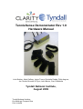
TennisSense Demonstrator Rev 1.0
Hardware Manual
John Buckley, Mark Gaffney, Javier Torres, Christelle Rodde, Philip Angove,
Jan Vcelak, Brendan O’Flynn, John Barton, Cian O’Mathuna
Tyndall National Institute,
August 2009
Tyndall National Institute
Lee Maltings, Prospect Row
Cork, Ireland
TennisSense Demonstrator Hardware User Manual
Acknowledgements
We would like to acknowledge our collaborative partners for the TennisSense
demonstrator at the CLARITY Centres in DCU and UCD and in particular, we
would like to acknowledge Ciarán Ó Conaire, Graham Healy, Kieran Moran
and Noel O’Connor.
In addition, we would like to acknowledge the support of Science Foundation
Ireland (SFI) in providing the funding for developing the hardware for this
demonstrator via the National Access Program (NAP) and Philip Angove at
the Tyndall National Institute. Tyndall is part of SFI's CLARITY Centre for
Sensor Web Technologies which is supported by Science Foundation Ireland
under grant 07/CE/I1147.
2
TennisSense Demonstrator Hardware User Manual
Table of Contents
1 Introduction.....................................................................................................4
2 WIMU Hardware.............................................................................................5
2.1 IMU Layer.................................................................................................5
2.2 Nordic Radio/ATmega128 Layer..............................................................6
2.3 NAP150 Board.........................................................................................7
2.4 Battery......................................................................................................7
2.5 Packaging.................................................................................................8
3 WIMU Specification.........................................................................................9
3.1 Physical Specifications overview.............................................................9
3.1.1 WIMU.................................................................................................9
3.1.2 Charger..............................................................................................9
3.1.3 Charger Connector..........................................................................10
3.2 Cable and connector..............................................................................11
3.3 Housing..................................................................................................12
3.3.1 WIMU...............................................................................................12
3.3.2 Radio Receiver................................................................................13
4 Labview GUI.................................................................................................14
4.1 WIMU binary output format....................................................................14
4.2 Reading IMU samples from Receiver....................................................14
4.3 Labview GUI Description........................................................................16
5 Important notices..........................................................................................18
5.1 Environmental Operating Conditions.....................................................18
6 References & Datasheets.............................................................................19
7 Quick Start Guide..........................................................................................20
3
TennisSense Demonstrator Hardware User Manual
1 Introduction
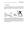
The TennisSense system consists of up to 6 wearable Wireless Inertial
Measurement Units (WIMUs) worn by a tennis player, a wireless receiver (Rx)
and a connected PC as illustrated in figure 1 below. This system allows for the
measurement and recording of the instrumented player’s kinematic motion
data.
Figure 1: TennisSense WIMU system overview
In operation, when a player is serving for instance, the body-worn WIMUs
monitor the movement of the player’s arm (upper, lower and wrist) as well as
the chest and torso. The sensor data are then transmitted wirelessly in realtime to the receiver (Base unit), which is linked to a PC via a USB cable. The
receiver features a serial over USB chip which allows the device to appear as
a virtual COM port, allowing the data to be easily accessed for display on the
included Labview program.
4
TennisSense Demonstrator Hardware User Manual
2 WIMU Hardware
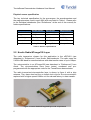
The assembled hardware of the WIMU is composed of a NAP150 Board
(power supply, battery management and integral dual-axis 70g/37g
accelerometer), an IMU layer (9x motion sensors), a 1Mbps Nordic Radio with
ATmega128 layer (wireless communication and processing) and a prismatic
lithium polymer battery (1230mAh).
IMU
Radio &
microcontroller
NAP150
Figure 2: Assembled WIMU (without battery)
2.1 IMU Layer
The Inertial Measurement Unit (IMU) layer contains multiple accelerometers,
gyroscope and magnetometer sensors arranged so that their axes of
sensitivity form orthogonal triplets. This allows for the monitoring of 6 degrees
of freedom motion data for each WIMU.
The IMU is shown in Figure 3 and features 3x single-axis gyroscopes, 2x
dual-axis accelerometers, 2x dual-axis magnetometers, a 12-bit ADC as well
as signal conditioning circuitry.
Figure 3: Details of sensors and axes of sensitivity for the IMU layer
5
TennisSense Demonstrator Hardware User Manual
Physical sensor specification
The key technical specification for the gyroscopes, the accelerometers and
the magnetometers used in each IMU layer are listed in Table 1. Please refer
to the individual datasheets (See “References” at the end of the manual) for
further specifications.
Number of axis
Range
Accelerometer
2 (x,y)
± 10g
Gyroscope
1 (z)
Up to ± 1200˚/s
Magnetometer
2 (x,y)
± 6gauss
Sensitivity
55mV/g
6mV/˚/sec
1mV/V/gauss
Part number
ADXL210
ADXRS300
HMC1052L
Manufacturer
Analog Devices
Analog Devices
Honeywell
Table 1: Sensors specifications
2.2 Nordic Radio/ATmega128 Layer
The radio transceiver chosen for this application is the nRF2401 (see
datasheet in “References”) from Nordic Semiconductor. The radio uses the
2.4GHz ISM band for communications with data transfer rates of up to 1Mbps.
The microcontroller is an ATmega128 (see datasheet in “References”) from
Atmel. The microcontrollers have been tested, numbered and preprogrammed with the appropriate code for the TennisSense demonstrator.
The radio transceiver/microcontroller layer is shown in figure 4 with a chip
antenna. They have also had the on board clock chip for the microcontroller
replaced with a higher speed 16MHz unit for reduced latency in data transfer.
Figure 4: Nordic Radio/ATmega128 layer with chip antenna
6
TennisSense Demonstrator Hardware User Manual
2.3 NAP150 Board
The NAP150 board delivers a regulated 5V supply from the attached 3.7V
lithium battery. It also features a supplemental 70g/37g dual-axis
accelerometer, ADXL278 from Analog Devices (see datasheet in
“References”).
Figure 5: NAP150 Board
Part number
Accelerometer
2 (x,y)
± 70g (x)
± 37g (y)
27mV/g (x)
55mV/g (y)
ADXL278
Manufacturer
Analog Devices
Number of axes
Range
Sensitivity
Table 2: NAP150 Accelerometer Specifications
2.4 Battery
The battery used is a 1230mAh LIP653450UC rechargeable Lithium Ion
Prismatic cell from Varta (see datasheet in “References”). This should allow
for several hours of operation before requiring recharging. The battery is
glued in place to prevent it from impacting with the electronics and improve
reliability.
7
TennisSense Demonstrator Hardware User Manual
Figure 6: LIP653450UC Rechargeable Lithium Ion Prismatic Battery (recent versions
have higher capacity than that illustrated)
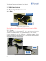
2.5 Packaging
The packaging is based around durable black ABS plastic enclosures. These
have a main body with posts for receiving 4 screws and a flat base plate with
four screw holes and “wings” to allow for securing the enclosures to other
objects. The units should be kept screwed shut to keep out moisture and dirt
which may cause premature failure. A small package of silica gel is also
included in each WIMU to reduce the chance of moisture damaging the
electronics. Aero-board is used to protect internal parts from damage due to
physical shocks such as tennis ball impacts.
Warning: Please do not disassemble without consulting with us first as
parts are attached to both the main body and the flat base plate which
are delicately connected.
Figure 7: Internal layout of parts for Tennis Sense WIMUs
8
TennisSense Demonstrator Hardware User Manual
3 WIMU Specification
3.1 Physical Specifications overview
3.1.1 WIMU
Power switch
Power
indicator
Charger
port
Figure 8: WIMU in large enclosure
Warning: Please only use the supplied chargers to charge the WIMUs.
3.1.2 Charger
The charger has a 2 colour status LED, this is red when a unit is being
charged and changes to green once the attached WIMU is fully charged.
It is not necessary to turn the WIMUs on or off before charging. During
charging the status LED and all electronics in the WIMU will be disconnected
from power so they will not be functional.
Gnd
+4.2V
DC
Figure 9: Charger with close up of connector
9
TennisSense Demonstrator Hardware User Manual
3.1.3 Charger Connector
The charger connector used is a standard 2.5mm diameter 2 pole (mono) jack
plug. The middle (tip) is positive, the outside (case) is at DC ground potential.
The charger output voltage (no-load) is 4.2V DC.
Warning: Ensure the polarity on all chargers used is correct before
plugging into a WIMU. Use a voltmeter to verify charger voltage is 4.2V
DC with polarity as shown.
Table 3 shows the electrical and physical specifications for the WIMU and
receiver units.
Interface
Operating
Voltage
Operating
current
Temperature
Operating Range
Outline
Dimensions
Weight
WIMU transmitter
Wireless (Nordic)
4.2 V (from charger)
3.7 V (from battery)
5 V (from NAP150)
170mA DC
Receiver
USB (1Mbps serial
over USB)
5V
120mA DC
0 to 55 °C
0 to 55 °C
125 x 50 x 25 mm (WIMU Large)
75 x 50 x 25 mm (WIMU Small)
107g (WIMU Large)
91g (WIMU Small)
190 x 110 x 60 mm
672g
Table 3: Electrical and physical specification
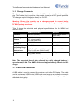
Note: The expected time of play allowed by a fully charged battery is
approximately 5-6h. The WIMU units need approximately 3h each to fully
charge.
3.2 Cable and connector
A USB cable is used to connect the receiver unit to the PC/laptop. The cable
used is a standard USB to mini USB cable and employs a screw on connector
to provide a robust connection and prevent it from being damaged or
detached during play.
10
TennisSense Demonstrator Hardware User Manual
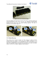
Figure 10: Receiver unit connected to laptop
Figure 11: Supplied USB cable
3.3 Housing
3.3.1 WIMU
Two types of WIMU enclosures have been provided for evaluation: a large
and small type. There are 5x WIMUs packaged in the large enclosure and 1x
WIMU packaged in the small enclosure as can be seen in figure 12.
Note: The small WIMU is a spare device that was used to evaluate a
smaller, lighter implementation that would make it more comfortable on
the wrist. However, the expected radio transmission range for the
smaller unit is less than for the large WIMU device.
11
TennisSense Demonstrator Hardware User Manual
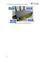
Figure 12: Set of 6x TennisSense WIMUs
The large WIMUs have dimensions of 125 x 50 x 25 mm, with the smaller type
having dimensions of 75 x 50 x 25 mm, any additional measurements
required can be taken from the scaled drawing supplied. The axes of
sensitivity are illustrated in figure 13.
W
W
U
U
V
V
Figure 13: Packaged WIMUs in large and small boxes showing axes of sensitivity
3.3.2 Radio Receiver
The receiver unit is shown in figure 14. The receiver is used to receive
wireless data from each of the 6 body-worn WIMU transmitters. It is
connected to the (laptop/PC) via a USB cable as shown. The receiver collects
data from the WIMU units and passes the received sensor data to the base
station via RS-232 for display, logging and data analysis.
12
TennisSense Demonstrator Hardware User Manual
USB
connector
Power
switch
Receiving
antennas
Power
indicator
Figure 14: TennisSense Radio Receiver unit
13
TennisSense Demonstrator Hardware User Manual
4 Labview GUI
The supplied GUI software is written in Labview (National Instruments Version
8.2). Note that any computer program (e.g. C, C++ Visual-C, Visual Basic etc)
that can access the data from the virtual COM port used by the receiver may
be used to read the captured sensor data from the receiver.
Note that an executable GUI (i.e. Labview GUI) is also included such that it
will run on any computer that does not have Labview installed. To run the
executable, it is required to install the Labview8.2.1 and Visa430 runtimes
which are both included on the CD.
Also note that to achieve the high data throughput required for this
application, a serial baud rate of 1Mbps is required. The exact serial settings
are listed in table 4.
4.1 WIMU binary output format
Receiver Serial (over USB) Connection Settings
Settings
Bits/second (bps)
Data bits
Parity
Stop bits
Flow control
Value
1M (1,000,000)
8
None
1
None
Table 4: Serial settings
4.2 Reading IMU samples from Receiver
A very simple serial data format is employed for each sensor measurement
and consists of:
•
•
•
•
Start of measurement identifier ( in this case the string “imu”)
WIMU number (1-6)
11 sensor readings
Two termination characters
The exact measured data structure is listed in table 5. To read the measured
ADC binary sensor data values from the COM port, simply wait for the start of
measurement identifier (“imu”), then capture the WIMU number, and 11
sensor readings and then wait for the next start of measurement identifier.
14
TennisSense Demonstrator Hardware User Manual
Byte
Description
Channel
ADC full
scale Voltage
1
Character "i"
NA
NA
2
Character "m"
NA
NA
3
Character "u"
NA
NA
4
WIMU number (1-6)
NA
NA
5
Accel U (Hi Byte)
0000XXXX
5V
6
Accel U (Lo Byte)
XXXXXXXX
5V
7
Accel V (Hi Byte)
0000XXXX
5V
8
Accel V (Lo Byte)
XXXXXXXX
5V
9
Accel W (Hi Byte)
0000XXXX
5V
10
Accel W (Lo Byte)
XXXXXXXX
5V
11
Gyro W (Hi Byte)
0000XXXX
5V
12
Gyro W (Lo Byte)
XXXXXXXX
5V
13
Gyro U (Hi Byte)
0000XXXX
5V
14
Gyro U (Lo Byte)
XXXXXXXX
5V
15
Gyro V (Hi Byte)
0000XXXX
5V
16
Gyro V (Lo Byte)
XXXXXXXX
5V
17
Mag W (Hi Byte)
0000XXXX
5V
18
Mag W (Lo Byte)
XXXXXXXX
5V
19
Mag U (Hi Byte)
0000XXXX
5V
20
Mag U (Lo Byte)
XXXXXXXX
5V
21
Mag V (Hi Byte)
0000XXXX
5V
22
Mag V (Lo Byte)
XXXXXXXX
5V
23
70g Minus U (Hi Byte)
0000 00XX
3.3V
*
24
70g Minus U (Lo Byte)
XXXX XXXX
3.3V
*
25
37g Plus V(Hi Byte)
0000 00XX
3.3V
*
26
37g Plus V (Lo Byte)
XXXX XXXX
3.3V
*
27
"New line" char
0x0A
28
"Carriage Return" char
0x0D
Comment
*Note: The 70g/37g sensor readings are voltage divided. Please using
scale factor of 1.555 to calculate true voltage
15
TennisSense Demonstrator Hardware User Manual
The serial data format delivered from the receiver is implemented using the
following embedded code:
void Serial_Data()
{
printf("imu"); //This text indicates the start of a string of
IMU data
putchar(data[0]); //Identify the data source (WIMU 1-6)
for (i=0;i<9;i++)// 18 IMU layer bytes
{
putchar(data[2*i+1]&0x0F);//High byte of AD7490 ADC conversion
putchar (data[2*i+1+1]);//Low byte of AD7490 ADC conversion
}
for (i=9;i<11;i++)// 4 bytes of 70g/37g accelerometer
{
putchar(data[2*i+1]&0x03);//High byte of MCU ADC conversion
putchar (data[2*i+1+1]);//Low byte of MCU ADC
}
putchar(0x0A);
putchar(0x0D);
}
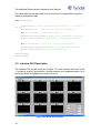
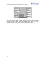
4.3 Labview GUI Description
The Labview GUI screen is shown in figure 15. It can be seen that each of the
11 sensor’s outputs (gyroscopes, accelerometers and magnetometers) for a
particular WIMU are graphed on screen at once.
Figure 15: Labview User Interface
16
TennisSense Demonstrator Hardware User Manual
Figure 16 GUI controls
Use “VISA resource (read)” to select the correct COM port for the receiver.
Choose the WIMU device using the dropdown menu above this. Serial
settings and bytes to read control should be left at default values.
17
TennisSense Demonstrator Hardware User Manual
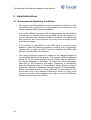
5 Important notices
5.1 Environmental Operating Conditions
18
•
The receiver should be placed as close to the centre of the tennis court
as possible with a direct line of sight between the antennae on the
receiver and the WIMUs for best reception.
•
If any of the WIMUs are powered off during operation the other WIMUs
will continue to transmit data and the base station will continue to
receive data from the remaining WIMUs as normal. The WIMU that
was turned off can be turned back on at any time and data will be
received once again.
•
If the receiver is powered off or the USB cable is removed during
operation (when the Labview program is running), even momentarily,
Labview will no longer be able to continue receiving the WIMU data
and the GUI will need to be restarted.
•
The correct COM port needs to be chosen in the Labview program to
receive WIMU data from the receiver. The specific COM port assigned
by the PC for the virtual serial port on the receiver can be checked in
the “Device Manager” in Windows. To access the “Device Manager”
right click on “My Computer” and select “Properties” or alternatively
press the “Windows button” & “Pause-Break” keys to bring up “System
Properties“, select the “Hardware” tab and press the “Device Manager”
button. Scroll down the list to “Ports (COM &LPT)” and expand it. You
should see a list of the assigned COM ports. When you plug in the
receiver a new entry should appear here, take a note of the COM port
number and use this in the Labview
TennisSense Demonstrator Hardware User Manual
6 References & Datasheets
Gyroscope: ADXRS300 from Analog Devices:
http://www.analog.com/static/imported-files/data_sheets/ADXRS300.pdf
Accelerometer: ADXL210 from Analog Devices:
http://www.analog.com/static/importedfiles/data_sheets_obsolete/OBSOLETE%20WATERMARK/ADXL210.pdf
Magnetometer: HMC1052L from Honeywell:
http://www.magneticsensors.com/datasheets/HMC105X.pdf
Radio Transceiver: Nordic nRF2401 Radio from Nordic Semiconductor:
http://www.nordicsemi.com/files/Product/data_sheet/nRF2401rev1_1.pdf
Microcontroller: ATmega128 from Atmel:
http://www.atmel.com/dyn/resources/prod_documents/2467s.pdf
Supplemental Accelerometer: ADXL278 from Analog Devices:
http://www.analog.com/static/imported-files/data_sheets/ADXL278.pdf
Battery: LIP653450UC Rechargeable Lithium Ion Prismatic from Varta:
http://www.vartamicrobattery.com/en/mb_data/documents/data_sheets/DS56491.PDF
19
TennisSense Demonstrator Hardware User Manual
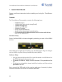
7 Quick Start Guide
Please read these instructions before installing and using the TennisSense
system.
Contents:
The TennisSense Demonstrator contains the following items:
-
5 WIMUs (Large)
1 WIMU with Velcro-elastic strap (Small)
1 Radio Receiver Unit
1 Screw-on USB cable
3 Battery Chargers
A copy of the User Manual
A copy of the internal parts layout drawing
CD containing drivers, documentation for all devices and Labview
code for the attached PC
Hardware Setup
Check if all the WIMU units are charged by switching on each of the WIMU
devices.
If the LED doesn’t light up, the battery may be discharged. Plug the charger
into the WIMU only after having checked the polarity before.
Software Setup
•
•
•
Use the files provided on the CD to install the serial over USB driver for
the FTDI chip used in the receiver unit.
If Labview is installed, simply use the Labview VI file provided on the
CD
If Labview is not installed, please install the Labview and Visa runtime
provided on the CD
Next, connect the USB cable to the receiver and screw it securely in place,
connect the receiver unit to the PC with the USB cable.
20
TennisSense Demonstrator Hardware User Manual
Turn on the power switch on the receiver. The green LED should illuminate
and the PC should detect the USB receiver as a USB serial device.
First Use
•
•
•
•
Connect receiver unit to the PC and note the specific COM port that the
receiver is assigned to
Run the Labview program provided and set the COM port used by the
Labview program to that used by the receiver
Put the WIMU units into the wearable pouches/straps and place on the
body. Switch the WIMU devices on, ensuring that the power indicator
LED is lit (if not the affected unit should be charged using the provided
chargers)
In the Labview program, select the WIMU of interest from the drop
down list at the top and ensure it is receiving data. Repeat for other
WIMUs.
Support
If you have any questions and require support, you can contact us via email
on mark.gaffney (x4023) john.buckley (x4401)
21