1
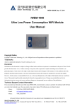
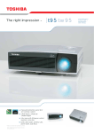
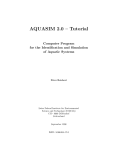
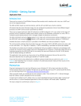
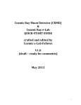
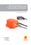
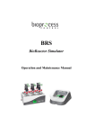
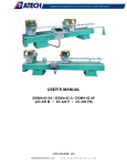
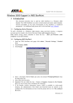
BT-1022UMv10, Sep. 17, 2010 BT-1022 Class 2 CSR BC04-EXT Bluetooth Flash Module User Manual Copyright Notice Copyright © 2009 Atech Technology Co., Ltd. All Rights Reserved. Reproduction without permission is prohibited. Trademarks Atech is a registered trademark of Atech Technology Co., Ltd. Disclaimer Information in this document is subject to change without notice and does not represent a commitment on the part of Atech. Atech provides this document “as is,” without warranty of any kind, either expressed or implied, including, but not limited to, its particular purpose. Atech reserves the right to make improvements and/or changes to this manual, or to the products and/or the programs described in this manual, at any time. Information provided in this manual is intended to be accurate and reliable. However, Atech assumes no responsibility for its use, or for any infringements on the rights of third parties that may result from its use. This product might include unintentional technical or typographical errors. Changes are periodically made to the information herein to correct such errors, and these changes are incorporated into new editions of the publication. Technical Support Contact Information If you encounter any technical issues while using BT-1022, do not hesitate to contact us @Atech. Our technical staff will help you resolve the technical issues. You can contact us by email or phone. The following is our technical contact: ‧Hours: 9:30AM to 5:30PM (GMT+08:00) ‧Email: [email protected] ‧Phone: +886.2.2377.0282 Atech Technology Co., Ltd. 7F., AAEON Building, No.43, Sec. 4, Keelung Rd., Taipei City 10607, Taiwan (R.O.C.) Tel:886-2-23770282 Fax:886-2-23770283 BT-1022UMv10, Sep. 17, 2010 Table of Contents 1. Overview .............................................................................................................................................. 3 2. Hardware ............................................................................................................................................. 4 2.1. Hardware Integration......................................................................................................................... 4 2.2. Pin description..................................................................................................................................... 5 2.3. Dimensions........................................................................................................................................... 7 2.4. Reflow Profile ...................................................................................................................................... 8 2.5. Packing and Label Information......................................................................................................... 8 3. Configuration and Operation ............................................................................................................ 9 3.1. Usage - AT Command Interface ........................................................................................................ 9 3.1.1. Configuration to connect to a PC ...................................................................................................... 9 3.1.2. Operation Modes............................................................................................................................... 10 3.1.3. Command Reference ........................................................................................................................ 10 3.1.4. AT Command Format ...................................................................................................................... 10 3.1.5. AT Command Response Format ..................................................................................................... 10 3.1.6. Set Commands................................................................................................................................... 12 3.1.7. Get Commands.................................................................................................................................. 13 3.1.8. Action Commands............................................................................................................................. 14 3.1.9. Default Setting................................................................................................................................... 14 3.1.9.1. Bluetooth Setting....................................................................................................................... 14 3.1.9.2. UART Setting ............................................................................................................................ 14 3.2. Usage – SPP (Serial Port Profile)..................................................................................................... 15 3.2.1. Pin Definition and Software Configuration.................................................................................... 15 3.2.2. Default Setting................................................................................................................................... 16 3.2.2.1. Bluetooth Setting....................................................................................................................... 16 3.2.2.2. UART Setting ............................................................................................................................ 16 Atech Technology Co., Ltd. 7F., AAEON Building, No.43, Sec. 4, Keelung Rd., Taipei City 10607, Taiwan (R.O.C.) Tel:886-2-23770282 Fax:886-2-23770283 BT-1022UMv10, Sep. 17, 2010 1. Overview Atech BT-1022 module is a field-proven software programmable CSR BC04 external Bluetooth v2.1+EDR module. With independent CPU and flash memory, the Bluetooth protocol stack is put on the module. The module makes adding Bluetooth connectivity easy because the host system does not need to handle the Bluetooth protocol stack. Since all Bluetooth protocol stacks are managed by the module, Bluetooth connectivity can be easily added to devices with 8- or 16-bit processors, eliminating the need to port existing applications to a more complicated platform and resulting in fastest time to market and reduced development costs. For users to configure and control the module from a PC or host processor, there are two options of standard firmware available. Firmware Option Typical Usage AT command interface Micro-controller type system to create Bluetooth wireless connectivity through UART interface. SPP (Serial Port Profile) Create a wireless remote serial port over Bluetooth connectivity. Through the reference and usage of AT command interface or SPP firmware developers and system integrators will easily evaluate the modules and Bluetooth technology. The purpose is to make the integration of the Bluetooth technology as seamless and easy as possible for Atech customers. This document will explain how to connect the BT-1022 module and establish Bluetooth communication with a Bluetooth enabled PC for reference. This document also describes the hardware interfaces to integrate the modules into the target system easily. The module is also available with several different firmware options for data and audio communications other than the standard firmware. Atech also provides custom firmware services with extra NRE charge. This can eliminate customer’s Bluetooth software effort and speed up the time-to-market. However, this is beyond the scope of this document. Please contact Atech sales representative for more information. Typical Applications Asset tracking Measurement / Remote Equipment Monitoring Scanners Atech Technology Co., Ltd. 7F., AAEON Building, No.43, Sec. 4, Keelung Rd., Taipei City 10607, Taiwan (R.O.C.) Tel:886-2-23770282 Fax:886-2-23770283 BT-1022UMv10, Sep. 17, 2010 Sensors & Controls Hand held terminals Industrial devices Point-of-Sale systems Personal Digital Assistants (PDAs) Automotive Diagnostics Unit 2. Hardware BT-1022 is a surface-mount module designed to be integrated to a system board as a wireless subsystem or standalone system. The hardware interface is grouped into the following functional blocks: Power supplies: VCC line should be connected to 3.3VDC. GPIOs: The PIO lines can be configured as general purpose 3.3V level digital inputs or outputs. UART: UART_TX, UART_RX, UART_CTS and UART_RTS are UART communication interface signals. UART_CTS and UART_RTS are not necessary to be connected if hardware flow control is not used. USB: USB interface is used for HCI mode only. PCM: PCM interface is used for audio codec. Special software programming support is required. SPI: SPI interface can be set to master or slave. This is software programmable. Special software programming support is required. RF: The RF_OUT should be connected to the antenna. Block diagram 2.1. Hardware Integration The module requires only 5 connections to power up and create a Bluetooth wireless connection. In the Atech Technology Co., Ltd. 7F., AAEON Building, No.43, Sec. 4, Keelung Rd., Taipei City 10607, Taiwan (R.O.C.) Tel:886-2-23770282 Fax:886-2-23770283 BT-1022UMv10, Sep. 17, 2010 simplest configuration, the hardware only needs the following connections: VCC, RF_OUT, UART-TX, UART-RX, and GND. VCC and GND pins connect to a regulated 3.3VDC power supply. The RF_OUT connects to a 2.4GHz antenna. The user connects UART-TX, UART-RX and ground pins to the host controller or a PC. The host controller or a PC can control the module and set up Bluetooth connection with the commands and settings defined in this document. The user can also use other functional blocks like GPIO, USB, SPI and PCM interfaces. Special software support is required to use these interfaces. 2.2. Pin description The following picture shows pinouts of BT-1022 from the top and bottom of the module. Pin Name Type Note 1 GND 2 NC 3 GND 4 TEST_A Internal Testing Use 5 TEST_B Internal Testing Use 6 RESET In 1. It should be pulled low for normal Atech Technology Co., Ltd. 7F., AAEON Building, No.43, Sec. 4, Keelung Rd., Taipei City 10607, Taiwan (R.O.C.) Tel:886-2-23770282 Fax:886-2-23770283 BT-1022UMv10, Sep. 17, 2010 operation (Active High) 2. A Reset will be performed after PIN6 being active for 1.5~4.0 ms 7 SPI_MISO In Internal Testing Use 8 SPI_CSB In Internal Testing Use 9 SPI_CLK In/Out Internal Testing Use 10 SPI_MOSI Out Internal Testing Use 11 UART_CTS In 12 UART_TX Out 13 UART_RTS Out 14 UART_RX In 15 VCC_1.8V Out 16 VCC_3.3V In 17 GND 18 PCM_OUT 19 PCM_SYNC 20 PCM_IN 21 Connect to host processor UART RX pin Connect to host processor UART TX pin Main power supply Out Codec Interface In/Out Codec Interface In Codec Interface PCM_CLK In/Out Codec Interface 22 USB+ In/Out 23 USB- In/Out 24 PIO7 In/Out General Purpose I/O 25 PIO6 In/Out General Purpose I/O 26 PIO5 In/Out General Purpose I/O 27 PIO4 In/Out General Purpose I/O 28 PIO3 In/Out General Purpose I/O 29 PIO2 In/Out General Purpose I/O 30 PIO1 In/Out Internal Used 31 PIO0 Out Internal Used 32 AGND Analog GND 33 RF_OUT Connect to antenna 34 AGND Analog GND 35 PIO8 In/Out General Purpose I/O 36 PIO9 In/Out General Purpose I/O 37 PIO10 In/Out General Purpose I/O 38 PIO11 In/Out General Purpose I/O Atech Technology Co., Ltd. 7F., AAEON Building, No.43, Sec. 4, Keelung Rd., Taipei City 10607, Taiwan (R.O.C.) Tel:886-2-23770282 Fax:886-2-23770283 BT-1022UMv10, Sep. 17, 2010 2.3. Dimensions Use the dimensions shown in the picture below to do the PCB layout for the host system or carrier board that will use BT-1022. Atech Technology Co., Ltd. 7F., AAEON Building, No.43, Sec. 4, Keelung Rd., Taipei City 10607, Taiwan (R.O.C.) Tel:886-2-23770282 Fax:886-2-23770283 BT-1022UMv10, Sep. 17, 2010 2.4. Reflow Profile 2.5. Packing and Label Information 00190E : Fixed Code for Atech XXXXXX : 6-digit MAC numbers Date Code : 2AYWXX for AT Command 2DYWXX for SPP (W: Manufacturing sequent Week) (Y: Manufacturing Year 201Y) Atech Technology Co., Ltd. 7F., AAEON Building, No.43, Sec. 4, Keelung Rd., Taipei City 10607, Taiwan (R.O.C.) Tel:886-2-23770282 Fax:886-2-23770283 BT-1022UMv10, Sep. 17, 2010 3. Configuration and Operation This section describes the basic configuration and operation for both usages – (1) AT Command Interface (2) SPP (Serial Port Profile) 3.1. Usage - AT Command Interface 3.1.1. Configuration to connect to a PC This section describes an example setup to connect a BT-1022 module to a PC for testing purpose. 1. Equipment list: Item Note PC Windows XP O/S with a COM port Power source Regulated 3.3VDC power source RS232 transceiver BT-1022 has only TTL level UART. A RS232 transceiver is required to interface the BT-1022 UART and PC RS232 port. 2.4GHz antenna A 2.4G antenna needs to be connected to the BT1022 module. The antenna can be a 2.9mm copper wire. RS232 cable Connects PC RS232 port to the RS232 transceiver. 2. Set up the BT-1022 hardware connection according to the following table: Connection BT-1022 pin Host system connection PWR 16 Regulated 3.3VDC power supply UART_TX 12 This pin goes to RS232 transceiver TTL TX input UART_RX 14 This pin goes to RS232 transceiver TTL RX Output GND 1 Ground RF_OUT 33 This pin should connect to a 2.4GHz antenna 3. Launch Hyper Terminal or Teraterm program, choose an available COM port and apply the port settings as: Item Setting Baudrate 9600 Data bits 8 Parity Stop Bits Flow control None 1 No flow control You can issue AT commands to the BT-1022. When you issue AT commands, you should see the response defined in later sections coming back from the BT-1022. Atech Technology Co., Ltd. 7F., AAEON Building, No.43, Sec. 4, Keelung Rd., Taipei City 10607, Taiwan (R.O.C.) Tel:886-2-23770282 Fax:886-2-23770283 BT-1022UMv10, Sep. 17, 2010 3.1.2. Operation Modes The BT-1022 standard firmware has 2 operation modes: Command mode and Data mode. The command mode is for the user to configure the BT-1022 module. In command mode, BT-1022 takes defined AT command set as described in later sections. The data mode is for data exchange with other connected Bluetooth devices. When BT-1022 is powered up, the default operation mode is command mode. To enter data mode, follow instructions in “Connect Command” section (as in chapter 3.1.8 Action Commands) to connect to another Bluetooth device. The user can use any preferred terminal program application like Teraterm, or Hyperterm to connect to the BT-1022 through COM port. Teraterm is recommended because of its popularity and user friendliness. You can go to the official Teraterm site to download the latest Teraterm application: http://en.sourceforge.jp/projects/ttssh2/releases/. 3.1.3. Command Reference The command interface of BT-1022 standard firmware is a modem-like AT command set. The following sections describe syntax and commands used in command interface for the user to configure and control BT-1022. 3.1.4. AT Command Format The AT command format is: AT<cmd><cr> or AT<cmd>=<value><cr> *** <cmd> represents specified command; <cr> represents \r Format Example Example AT+<cmd><cr> AT + GLN \r Host send Get local name command AT+<cmd>=<value><cr> AT + PIN = 12345678 \r Host send Set pin code command 3.1.5. AT Command Response Format The AT command response format is: <cr><lf><Response Code><cr><lf> *** <cr> represents \r; <lf> represents \n There are two categories of Response Code: Atech Technology Co., Ltd. 7F., AAEON Building, No.43, Sec. 4, Keelung Rd., Taipei City 10607, Taiwan (R.O.C.) Tel:886-2-23770282 Fax:886-2-23770283 BT-1022UMv10, Sep. 17, 2010 Category 1 Response Code Example Meaning \r \n 1 \r \n OK \r \n 2 \r \n ERROR \r \n 3 \r \n UNKNOWN \r \n 4 \r \n FAILED Condition & Notes ie, AT+INQ = 000000,15,10 \r (1 <= maxResponses <= 10) ie, AT+ABC \r (command ABC is not available) ie, command/response successfully finished; result to be no match Category 2 Response Code Example Meaning Condition & Notes state: 1 : sppDevReady \r \n +STA:state \r \n STATE: 2 : sppDevInquiring to indicate current status 3 : sppDevConnecting 4 : sppDevConnected scanMode: 0 : hci_scan_enable_off \r \n +SM:scanMode \r \n SCANMODE: 1 : hci_scan_enable_inq to indicate current scan mode 2 : hci_scan_enable_page 3 : hci_scan_enable_inq_and_page \r \n +INQ:address, classOfDevice \r \n INQUIRY result \r \n +INQC \r \n INQUIRYCOMPLETE \r \n +COD: classOfDevice \r \n to indicate class of device (local \r \n +LA:address \r \n LocalAdress \r \n +LN:name \r \n \r \n +SCM:securityMode \r \n address: 12 hexadecimal classOfDevice: 6 hexadecimal classOfDevice: 6 hexadecimal device) address: 12 hexadecimal Local Name: Return code of get local name command Sscuritymode: to indicate current security mode User friendly name of the local device securityMode: 0 : security_off, encyption_off 1 : security_on, encyption_off Atech Technology Co., Ltd. 7F., AAEON Building, No.43, Sec. 4, Keelung Rd., Taipei City 10607, Taiwan (R.O.C.) Tel:886-2-23770282 Fax:886-2-23770283 BT-1022UMv10, Sep. 17, 2010 2 : security_on, encyption_on \r \n +RN:address,name \r \n address: 12 hexadecimal Remote Name: Return code of get name: user friendly name of remote name command the remote device address: 12 hexadecimal \r \n +SSPP:address,result \r \n SEARCHSPP : Return code of search Result: SPP profile command 0 : SPP profile not found 1 : SPP profile found \r \n +CD:address \r \n \r \n --- \r \n \r \n +++ \r \n \r \n +OM:mode \r \n CONNECTED : Indication of SPP address: 12 hexadecimal connection Connected : The last result code before entering data mode Disconnected : The first result code after returning to command mode OPERATIONMODE : Return code of get operation mode command 3.1.6. Set Commands The Set commands are for the user to set the BT-1022 configuration. SET Commands Command Set Conditions & Notes scanMode: Set inquiry scan and page scan mode command 0 : hci_scan_enable_off AT + SSM = scanMode \r 1 : hci_scan_enable_inq 2 : hci_scan_enable_page 3 : hci_scan_enable_inq_and_page pinCode: Set pin code command AT + PIN = pinCode \r Set local name command AT + SLN = localName \r default: 0000 4< pincode length <16 1 <= local name length <= 16 Atech Technology Co., Ltd. 7F., AAEON Building, No.43, Sec. 4, Keelung Rd., Taipei City 10607, Taiwan (R.O.C.) Tel:886-2-23770282 Fax:886-2-23770283 BT-1022UMv10, Sep. 17, 2010 baudRate: UART Baud rate =baudRate/0.004096 Some common values are: 9k6 baud - 39 Set Baud rate command 19k2 baud - 79 AT + SBR = baudRate \r 38k4 baud - 157 57k6 baud - 236 115k2 baud - 472 230k4 baud - 944 460k8 baud - 1887 921k6 baud - 3775 1382k4 baud - 5662 Set class of device command AT + SCOD = classOfDevice \r classOfDevice: 6 hexadecimal class of device securityMode: Set security mode command AT + SSCM = securityMode \r 0 : security_off, encyption_off 1 : security_on, encyption_off 2 : security_on, encyption_on Delete all authorized devices command AT + DA \r 3.1.7. Get Commands GET Commands Command Set Get inquiry scan and page scan mode command AT + GSM \r Get local name command AT + GLN \r Get class of device command AT + GCOD \r Get local address command AT + GLA \r Get security mode command AT + GSCM \r Get remote name command AT + GRN = address \r Get state command AT + STA \r Conditions & Notes address: 12 hexadecimal Bluetooth Device Address Atech Technology Co., Ltd. 7F., AAEON Building, No.43, Sec. 4, Keelung Rd., Taipei City 10607, Taiwan (R.O.C.) Tel:886-2-23770282 Fax:886-2-23770283 BT-1022UMv10, Sep. 17, 2010 Get operation mode command AT + GOM \r 3.1.8. Action Commands The actions commands are for the users to control the BT-1022 to do certain actions. The defined actions are: Inquiry, Connect, Reset and Search SPP profile. ACTION Commands Command Set Conditions & Notes classOfDevice: 6 hexadecimal class of device filter set 000000 -- notified of all devices within range regardless of their class of device. Inquiry command AT + INQ = classOfDevice, maxResponses, timeout \r audio/ video to be 000400 ; headset to be 200404 maxResponses: 1 <= maxResponses <= 10 timeout: 1(1.28 seconds) <= timeout <= 48(61.44 seconds) Connect command AT + D = address \r Reset command AT + RST \r Search SPP profile command AT + SSPP = address \r address: 12 hexadecimal Bluetooth Device Address address: 12 hexadecimal Bluetooth Device Address 3.1.9. Default Setting The following sections describe the default settings when BT-1022 module is out of Atech factory. 3.1.9.1. Bluetooth Setting Mode: Master Profile: SPP Local Name: BT SPP PIN CODE: “1234” Discoverable mode (Pairing Mode) will continue without time-out following VCC 3.3V input. 3.1.9.2. UART Setting Baudrate: 9600 Atech Technology Co., Ltd. 7F., AAEON Building, No.43, Sec. 4, Keelung Rd., Taipei City 10607, Taiwan (R.O.C.) Tel:886-2-23770282 Fax:886-2-23770283 BT-1022UMv10, Sep. 17, 2010 Flow control: No flow control 3.2. Usage – SPP (Serial Port Profile) 3.2.1. Pin Definition and Software Configuration Local Name BT SPP + LAP (read by USB dongle) PIN code Baudrate Configurable (1200 ~ 115200 bps) 1234 Pin Config Function PIO 0 (Out) PIO 1 (Out) PIO 2 (In) PIO 3 (In) PIO 4 (In) PIO 5 (In) PIO 6 PIO 7 PIO 8 PIO 9 PIO 10 PIO 11 AIO A AIO B (Out) (In) (In/Out) (In/Out) (In/Out) (In/Out) (NA) (NA) Spec Internal Used Internal Used Baud Rate Switch 1 / UART Configuration Switch 1 Baud Rate Switch 2 / UART Configuration Switch 2 Baud Rate Switch 3 / UART Configuration Switch 3 Hardware Flow Control Switch / DTE-DCE Switch LED Reset Button DTR DSR DCD RI Described below Described below Described below Described below Described below Described below Output in DTE / Input in DCE Input in DTE / Output in DCE Input in DTE / Output in DCE Input in DTE / Output in DCE #If Reset Button (PIO7) was pressed (high) while power on reset, app would be in configuration mode. If Reset Button (PIO7) was opened (low) while power on reset, app would be in operation mode. #In configuration mode, PIO2 ~ PIO5 serves as configuration switches. PIO2: low => one stop bit, high => two stop bits. PIO3: low => no parity bits, high => one parity bit. PIO4: low => odd parity, high => even parity. PIO5: low => DTE, high => DCE. When the configuration is saved in PS keys, PIO6 (LED) will be always on. #In operation mode, PIO2 ~ PIO4 serves as Baud Rate switches. PIO4 / PIO3 / PIO2 : Baud Rate 000 : 115200 001 : 57600 Atech Technology Co., Ltd. 7F., AAEON Building, No.43, Sec. 4, Keelung Rd., Taipei City 10607, Taiwan (R.O.C.) Tel:886-2-23770282 Fax:886-2-23770283 BT-1022UMv10, Sep. 17, 2010 010 : 38400 011 : 19200 100 : 9600 101 : 4800 110 : 2400 111 : 1200 #In operation mode, PIO5 switches hardware flow control on (high) / off (low). #In operation mode, LED (PIO6) blinks once per second in discoverable mode and blinks twice every two seconds if connected. #In operation mode, Reset Button (PIO7) can be used (pressed) to disconnect from peer device and return to be discoverable. 3.2.2. Default Setting The following sections describe the default settings of BT-1022 module for BT-1022 module with Atech SPP firmware. All unused PIO pins 3.2.2.1. Bluetooth Setting Mode: Master Profile: SPP Local Name: BT SPP + LAP PIN CODE: “1234” Discoverable mode (Pairing Mode) will continue without time-out following VCC 3.3V input. 3.2.2.2. UART Setting Baud Rate: 115200bps Data Bits: 8 Parity: No parity Stop Bits: 1 Atech Technology Co., Ltd. 7F., AAEON Building, No.43, Sec. 4, Keelung Rd., Taipei City 10607, Taiwan (R.O.C.) Tel:886-2-23770282 Fax:886-2-23770283