1
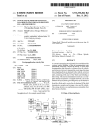
CosmicRayMuonDetector(CRMD)
&
CosmicRaye-Lab
QUICK-STARTGUIDE
craftedandeditedby
Cosmice-LabFellows
V1.0
(draft–readyforcomments)
May2013
1
2
QuarkNet Cosmic Ray Muon Detector (CRMD) Assembly Instructions
for Series 6000 DAQ
Version: 2.13
Date: 17 February 2012
Please send comments to: [email protected]
Read Me First
Document Purpose
How to build a cosmic ray muon detector (CRMD) from components and enable raw data to flow into a
"capture" file on the users data computer.
Not Covered: Configuring CRMD, data rate, plateauing individual counters, details of serial
communication application (“hyperterm” or “ZTerm”). These details are covered in the “QuarkNet
Cosmic Ray Muon Detector User's Manual”; see http://www.i2u2.org/elab/cosmic/library/resources.jsp
Assembly Required
User must assemble some components: PMT, scintillator, wrapping materials, support tube
(Previously assembled components: GPS, DAQ, PDU)
counter
Warnings
• Do not handle the scintillator material with bare hands.
• Read Material Safety Data Sheet (MSDS) for optical couplant.
• Seat all electrical plugs completely: Improperly seated plugs can lead to power shorts.
• Avoid excess pressure on the PMT window. Fragile!
• PMT power up: Make sure that voltage levels are set to minimum for power up (control stems
on the PDU potentiometers, rotated counterclockwise).
• Do not power up until all components are plugged into their proper connections.
• GPS Module (gray box) must remain indoors; it is not weather proof.
Check Parts
Verify. If parts are missing, contact your QuarkNet mentor or Cosmic Ray e-Lab HelpDesk:
(https://www.i2u2.org/elab/cosmic/teacher/forum/HelpDeskRequest.php)
Instruction Sections
1. Parts List
2. Quick Start
3. Counter Assembly Instructions
4. Detailed PLUG-IN Sequence
5. POWER-UP Sequence
6. Commissioning Sequence
7. Troubleshooting
8. FAQs
9. Addendum
1a) Parts List – Subcomponents
Counters
Scintillators
Heavy Gauge Aluminum Foil
Lightproof Black Wrapping Material
Support Tubes
Photomultiplier Tubes (PMTs)
Optical Couplant
(4) To be assembled from the following pieces:
(4) 10”x12”x1/2” scintillator plastic blocks with polished
edges and light guide “cookie” glued to one corner.
Handle with cotton gloves.
(1) 38”x64” (approx) piece for covering scintillator.
(1) 27”x40” (approx) piece for covering scintillator.
(4) 24” lengths of PVC pipe slotted to accept wrapped
scintillator and to align photomultiplier tube (PMT) with
optical cookie.
(4) SensTech Model P30CW5 photodetector packages,
including cables for signal, power and control.
Handle with care!
(1) Small film-type canister containing optical grease used
to interface the PMT to the light guide “cookie.”
3
Signal Extension Cables for PMTs
Power Extension Cables for PMTs
Power Distribution Unit (PDU)
PDU Power Cable
Cloth Gloves
Specification Sheets
Safety Data Sheet
(4) 50 ft. cables with male BNC connectors on each end
(4) 50 ft. stereo audio cables with one male and one female
connector, to extend power and control circuits from PMTs
(1) Box with 5VDC power input and 4 outputs including
potentiometer controls for each control circuit
(1) 6 ft. mono audio cable, male connectors on both ends,
to get power for the PDU from the connection provided on
the DAQ circuit board
(2) Pair clean soft cotton gloves used for handling
scintillator materials to avoid dirt, scratches and fingerprints
(4) Spec sheets for PMT, scintillator plastic, optical
couplant, GPS antenna
(1) Material Safety Data Sheet (MSDS) for optical couplant
1b) Parts List – Large Components
GPS Receiver Assembly (GPS)
Data Acquisition Circuit Board (DAQ)
USB Interface Cable
Power Supply
(1) The GPS receiver and interface adapter (GPS module)
are in a small gray plastic box to which you will attach three
items:
a) - the 100 ft. CAT-5 standard network cable which
connects the GPS to the DAQ
b) - the temperature sensor cable with the red weatherproof
coating on the sensing end
c) - the GPS antenna with 9 ft. MCX cable; antenna has
magnetic base
(1) This circuit board contains the logic, timing, multipliers,
and discriminators for processing the input signals from the
counters and creating the output data stream. It has
interfaces to the counters, the GPS and your PC. Many of
the devices on this circuit board have been preset. Do not
change any settings unless specifically asked for in the
instructions. The circuit board has been loaded with the
current revision level of QuarkNet firmware.
(1) 9 ft. USB2.0 A to B interface cable for connecting the
DAQ to your PC's USB port.
(1) Power supply with 5VDC 1A output, female connector,
to provide power to the DAQ.
(Note: You must provide a PC or Mac with a terminal emulator program such as “hyperterm” or "ZTerm"
to display data and send keyboard commands to the DAQ.) (Connections with a Linux OS are possible.
Contact: Cosmic Ray e-Lab HelpDesk.)
2) Quick Start
Steps leading to a working CRMD:
Assemble four counters—section 3.
Plug-in components—section 4.
Power up – section 5.
Commission CRMD – section 6.
Take data: Capture data to a file. (See CRMD Users Manual.)
Measure geometry and upload to cosmic e-Lab. (See CRMD Users Manual.)
3) Counter Assembly (Read entire section before starting)
General Tips
• When working with electrical tape, pull tape off roll, then let it “relax” by hanging it vertically and
letting it rest for 3-5 minutes.
• Handle scintillator with the provided cotton gloves.
• The PMTs are expensive electronic devices. The windows are easily damaged by excessive
pressure. DO NOT force the PMT against the scintillator cookie.
Assembly Steps
4
•
•
•
Wrap the scintillator.
Attach the photomultiplier tube.
Assemble the PVC support.
Parts Provided
Plastic scintillator with cookie
Aluminum foil
Lightproof black wrapping material
User Provided Materials
3/4" wide black vinyl electrical tape
3" (or 2”) wide black vinyl electrical tape
Tools Needed
Scissors
Razor blades
Multimeter - VOM
Photomultiplier Tube (PMT)
PVC support
Optical grease
1/2" Teflon plumber’s tape
Scotch tape
Straight edge
Protractor
Step 1: Wrap the Scintillator.
The scintillator must be wrapped to block transmission of ambient light. Aluminum foil and black wrapping
material are provided. The wrapping and taping are much like wrapping a present. Lay out the material,
lay the scintillator down, fold and tape.
•
•
•
•
•
•
Cut aluminum foil: four pieces sized 18” X 26” (45.7 cm x 66.0 cm).
Lay the foil on a workspace with “shiny” side up. Smooth foil.
Lay the scintillator at one end of the foil. Use cotton gloves!
Fold the foil over one of the long edges.
Fold foil around the other plate edges and tape.
Trim foil to cover just behind the counter cookie using a razor blade.
5
Completely cover the scintillator. While minor
wrinkles are acceptable, avoid holes or tears.
Add additional “repair” pieces to patch any
noticeable tears or holes.
•
•
•
•
•
•
•
Use Teflon plumber’s tape to wrap the edges
of the cookie to block light; do not cover the
face. Avoid scratching the face of the cookie.
This is the transmission window for the light
pulses.
Cut black wrapping material: four pieces sized 9 1/2” X 23 1/2” (24.1 cm x 59.7 cm).
Lay the black wrapping material down on a workspace with the reflective side up, black side
down.
Lay scintillator at one end of the material.
Fold black wrapping material around the short edge opposite the cookie.
Tape edge with electrical tape to hold the material in place.
Flip scintillator, pull material tight and tape other edge.
Completely cover remaining exposed foil using 1” and 3” electrical tape.
• Reinforce each corner with extra tape using
“gift-wrap” folds. Be creative but avoid bulk.
• Trim the material behind the cookie and
secure with electrical tape.
• Apply a piece of 3” electrical tape to protect
the black material from damage due to
sharp edges of the PVC support tube. Start
at the cookie and run the tape across the
face at an 18° angle measured from the
long side. Do this on both sides of the
scintillator.
Step 2: Attach the photomultiplier tube.
6
DO NOT force the PMT against the cookie.
• Remove the PMT cap; save for PVC pipe
plug
• Apply a small amount (about the size of a
pea) of optical couplant to the PMT
window.
• Hold the PMT in contact with the cookie
face.
• Gently press the two faces together.
Gently!
• Wrap the joint—use 3” electrical tape.
Step 3: Assemble the PVC support tube.
• Carefully slide the assembly into the PVC support tube; be sure to not crimp the wires. Stop if
there is excessive resistance.
• Guide the assembly until the PMT is 1-2 inches from the end of the slot; the PVC will extend
beyond the assembly.
7
• Measure the angle between the PVC support tube and the long side of the assembly. Adjust the
PVC support until this angle is 18°. This will maintain alignment between the cookie face and
PMT window.
• Wrap the outside of the PVC tube with 3” tape near the PMT-cookie interface.
• Tape the PVC tube to the face of the scintillator assembly with 3” electrical tape.
• Slide the PMT cap into the end that extends beyond the scintillator assembly and circle tube with
tape; this provides pressure point to clamp the assembly inside the PVC slot.
4) Detailed PLUG-IN Sequence
Plan locations and layout for your GPS, counters, DAQ and PDU, and computer.
Preplanning:
• Place the GPS antenna at a window with at least a partial southern exposure, if possible, where it
has a clear view of the vertical sky. The antenna is sensitive enough to acquire satellites from
inside the window. The antenna may be placed outside, along with the temperature sensor, but not
the gray box containing the GPS module. The gray GPS module box MUST remain inside. The
GPS module may be located up to 100 feet from the DAQ using the CAT-5 cable provided. The
GPS antenna has a magnetic base. Alternate CAT-5 cable may be used especially to reach an
outside window in another room; user provided.
• DAQ lives near the data computer.
• PDU enables control of voltage levels and power supply to PMTs. Must be within 50 ft. of
counters. Extensions are possible; user-supplied.
• Counter placement driven by experiment type: array or stacked (See CRMD Users Manual.)
DO NOT POWER UP SYSTEM UNTIL ALL COMPONENTS ARE IN PLACE to avoid overvoltage to
the PMT. Make sure all cable connections are completely seated.
1. Power Supply, female connector
DAQ male jack (power supply may differ from photo)
Note: Do not plug into wall outlet at this step.
8
2. DAQ female jack
PDU (single, side outlet): 6 ft. PDU power cable, male mono connectors
3. PMTs/counters (4)
PDU (four, side outlets): 50 ft. power extension cable, stereo
connectors
Note: check all power connections; must be fully seated.
4. PMTs/counters BNC connections (4)
DAQ BNC connections: 50 ft. BNC signal ext cables
5a. GPS antenna
GPS Receiver Assembly: black MCX cable
5b. temp sensor
GPS Receiver Assembly: gray phone cable, red sensor end
5c. GPS Receiver Assembly
DAQ: CAT-5 green network cable
Note: CAT-5 cable plugs into DAQ "GPS IN", not "GPS FANOUT".
6. DAQ
computer USB port: USB 2.0 A to B cable
9
5) POWER-UP Sequence (after plugging in all components)
1. Set potentiometers on the PDU to minimum (fully rotate counterclockwise).
2. Plug 5V DC power supply into 110V wall outlet.
3. Check DAQ: two yellow LEDs next to USB for power
3V, 5V
4. Verify power to GPS module: red/green LED on module box
Red blinking: power up condition, initializing
Red/green combination: searching and # of sats
Green only: long & # of short
# indicates "healthy" sats
5. Check control voltage on each PDU channel: black socket
ground; yellow socket
positive
6) Commissioning Sequence
1. Install USB approprite driver from "SiLabs" vendor onto data computer: See Addendum below.
Note: URL has changed.
2. Open USB connection from computer to DAQ; use terminal emulator: “hyperterm” or “Zterm.”
(See CRMD Users Manual - Appendix C: Terminal Emulator Setup.) (default baud: 115200;
flow control: Xon/Xoff)
3. Verify GPS signal on DAQ; white LED (marked 1PPS) should be blinking next to GPS jack (GPS
IN). (may take 1 hour to lock signal)
4. Check number GPS satellites; run 'DG' command.
5. Plateau and test counters. (for plateauing instructions see CRMD Users Manual – Chapter 6 or
Cosmic Ray e-Lab: http://www.i2u2.org/elab/cosmic/library/resources.jsp
PowerPoint and
Spreadsheet
6. Configure DAQ for coincidence, gate width, and delay; run "V1" and "V2" commands. (See CRMD
Users Manual – Chapter 6.) (defaults: gate = 100ns; delay = 40ns. Set to defaults: DAQ
command 'SA 2'.)
7. Take data: begin “Capture Text” with “hyperterm” or “Zterm."
8. Enter list of commands to capture configuration state of DAQ:
CD
COUNTER DISABLE (stop data flow)
H1
HELP 1
H2
HELP 2
DG
GPS
DS
SCALAR COUNTS
DC
CONTROL REGISTERS
DT
TIME CONTROL
BA
BAROMETER
TH
TEMPERATURE
TI
TIME
TL
THRESHOLD VOLTAGES
SN
DAQ SERIAL NUMBER (DAQ ID NUMBER)
V1
VIEW REGISTERS
V2
VIEW VOLTAGES
ST 3 5
PRINT STATUS LINES EVERY 5 MINS
SA 1
SAVE CONFIGURATION
CE
COUNTER ENABLE (start data flow)
9. Upload data to Cosmic e-Lab:
https://www.i2u2.org/elab/cosmic/data/upload.jsp
UPLOAD
10. Measure and input CRMD geometry to Cosmic e-Lab:
https://www.i2u2.org/elab/cosmic/geometry/
GEOMETRY
7) Troubleshooting
• If the DAQ does not respond to 'hyperterm' and 'ZTerm' commands, check the USB cable
connection, unplug the USB cable, reboot, replug cable, and open fresh 'hyperterm'.
•
If the Terminal Emulator is not responding, push the DAQ "Board Reset" button.
8) FAQs
• How do I reset DAQ?
Pushing the “BOARD RESET” button next to the “GPS FANOUT” will do a TOTAL reset.
Pushing the button “COUNTER RESET” next to the "count" display will only reset the display.
•
I have Vista or Win7 OS and 'hyperterm' is missing. What to do?
10
a) MicroSoft has given permission to move 'hyperterm' from an older Windows OS. On WinXP
or Win2000 find:
hypertrm.exe (in Program Files\Windows NT)
hypertrm.dll (in Windows\System32).
Copy them to a common folder on Vista or 7. Double click 'hypertrm.exe' to launch.
b) Try open source application: PuTTY
http://www.chiark.greenend.org.uk/~sgtatham/putty/download.html
User configuration required.
•
Topics found in QuarkNet CRMD Users Manual:
PC connection
DAQ commands
Capture data: hyperterm or ZTerm
Placement of counters and GPS
Plateauing
Coincidence
Discrimination
Pressure/Temp measure
CPLD frequency
Addendum
QNET 2.5 (6000 Series DAQ) USB DRIVER INSTALLATION
Fermilab, July 22, 2008
The following are instructions for installing QNET USB drivers on a personal computer. Most of this document is
for Windows PC users. Note: Install the drivers before making the first USB connection to the DAQ.
To get the most recent version of the drivers go to (http://www.silabs.com). Search for ‘VCP Drivers’ or ‘CP210X’.
Below is an example listing of the driver packages for Mac, Win, and Linux.
Download the driver package you need. Go here:
https://www.silabs.com/products/mcu/Pages/USBtoUARTBridgeVCPDrivers.aspx
VCP Driver Kit for your OS
Windows OS CP210x_VCP_Win2K_XP_S2K3.zip
Mac OS Mac_OSX_VCP_Driver.zip
Linux OS cp210x-3.0.0.tar.gz
Note: some older DAQs have an outdated URL printed on the back of the card. Use the above.
Installing the driver on a Windows PC.
• Install CP210x driver.
• Now connect the USB port on the PC to the Qnet DAQ board.
• New hardware found wizard will open. The wizard should find the drivers and complete the install.
• HyperTerminal can now be used to connect to the DAQ. Connect using the assigned port. This is usually
the highest port number that is selectable on the Properties menu under File option for HyperTerminal.
1. Connect using : usually COM3 (for additional help, see will not connect to DAQ)
2. click on configure button and make the following Port Settings
3. Bits per second: 115200 (BAUD)
4. Data bits
:8
5. Parity
: None
6. Stop bits
:1
7. Flow control : None
11
The following is for Windows users if HyperTerminal will not connect to DAQ.
After installing driver do the following to find the COM port assigned to CP210x USB.
• Note: The Cp210x drivers have been installed.
• Connect Qnet to the PC using a USB cable.
• Right click on 'My Computer" (WinXP example)
• click on Properties
•
click Hardware
•
click Device Manager
•
click Ports (COM & LPT)
• CP210x USB to UART Bridge Controller COM (n). COM (n) is the port number for HyperTerminal.
12
Cosmic Ray Detector Parts
1.
2.
3.
4.
5.
6.
7.
8.
9.
10.
11.
12.
13.
14.
15.
16.
Counter (Collectors) - Scintillator, photomultiplier tube, PVC pipe (4)
BNC signal extension cables (4)
Data acquisition (DAQ) board (Note: Hold on edges and place only on nonconductive
surfaces like the antistatic bag it arrives in.)
Ethernet cable for GPS unit (CAT 5)
GPS module
GPS antenna
Temperature sensor
5 VDC power supply
PDU power cable
Power distribution unit (PDU)
Power extension cable for PMTs (4)
USB cable
Personal computer
Digital Volt-Ohm meter and surge power strip (not pictured)
Optional - Heavy cloth to block light and black electrical tape
Numbered wire labels are available from electronics and hardware stores.
Figure 1
Version 1.0, November 2012
13
Wiring Instructions
Note: All number references correspond to the numbers in Figure 1.
1.
Attach the GPS antenna (6) and temperature sensor (7) wires into one end of the small GPS module
(5).
2.
Position the GPS antenna (6) outside for best signal. (It might work through a window, but best
results are external placement.) The thermometer sensor is often placed with the GPS, but this may
depend on the design of the specific experiment.
3.
Plug the CAT 5 [it looks like computer network cable (4)] into other end of GPS module (5).
4.
Run the CAT 5 cable (4) to the DAQ’s (3) “GPS-IN” port (adjacent to the four data channel ports).
5.
Plug in surge protector (not shown). While OFF, plug the 5 VDC power supply (8) into the surge
protector. NOTE: Leave the surge protector OFF until all assembly is completed!
6.
Plug other end of the 5 VDC power supply (8) into the DAQ (3). This is the opposite corner of GPSIN receptacle.
7.
The power distribution unit (10) and the DAQ (3) are joined together by the PDU power cable (9).
The port on the DAQ is next to 5 VDC power supply cord. Label each channel and connector on the
PDU: 0, 1, 2, and 3, respectively. This can be done with marker, tape, or labels. Knobs can be
purchased from many electronics vendors, such as DigiKey.
8.
Stack the four scintillators (1) so the rectangular sections are above each other with corners and
edges aligned, making sure PVC pipes alternate to form a “V” shape.
9.
Label (on the PVC part of each scintillator), using tape or marker, 0, 1, 2, and 3, respectively,
starting from the top with 0.
10. Label the BNC signal extension cables 0, 1, 2, and 3 at each end using labeling tape. (2) [Numbered
wire labels are available from electronics and hardware stores.]
11. Label the power extension cables (11) for the photomultiplier tubes (PMTs) 0, 1, 2, and 3 at each
end.
12. Connect BNC signal extension cables 0, 1, 2, and 3 (2) at one end to black cords that are exiting the
collectors, making sure to connect 0 to 0 and 1 to 1, etc. Connect the other ends to the DAQ’s (3)
corresponding numbered CH ports 0–3.
13. Connect power extension cables 0, 1, 2, and 3 (11) at one end to multicolored cords that are exiting
the collectors, making sure to connect 0 to 0 and 1 to 1, etc. Connect the other ends to the side of the
power distribution unit (10) in 0–3 order.
14. Plug the USB cable (12) into the DAQ (3) and plug the other end into your personal computer (13).
15. It is now safe to turn on the surge protector. Lights on the DAQ should light up. (Blue lights indicate
counts for each channel and red numeric display gives the number of coincidences.)
14
From“6000”CRMDUsersManual
Appendix C: Terminal Emulator Setup
Hyperterminal
Hyperterminal,aterminalemulation
program,oftencomeswithaWindowsbasedPCorcanbedownloadedfromthe
Internet.HyperterminalallowsthePC’s
monitortodisplaythedatathatissent
fromtheDAQboardtothePC’sserialport
orUSBport.Note:Hyperterminalno
longercomesasastandardapplication
withWindowsVistaorWindows7.
ContacttheCosmicRaye-LabHelpDesk
forsolution:
https://www.i2u2.org/elab/cosmic/teac
her/forum/HelpDeskRequest.php
Oncethisprogramisopened,awindow
appearsthatasksforanameforthe
connectionthatyouaremaking.Entera
convenientnamesothatinthefutureyou
willnothavetogothroughtheinitial
setuproutineeachtimeyouwantto
establishaconnection.
Onceyouselect“OK,”thewindowshown
inFigure38appears.Youneedtoselect
theCOMportthattheDAQboardis
connectedtoonthebackofyour
computer.
ChoosetheCOMportthattheDAQ
boardispluggedintoonthebackof
yourcomputer(SerialportisCOM1
andUSBisCOM3forthiscomputer.)
COM3,theUSBport,isselectedhere.
Figure38.ThiswindowillustrateswheretheCOMportselectionismade,
whichtellsthecomputertowhichporttheDAQboardisconnected.
Youneedtochangetwosettingsfrom
theirdefaultvaluesonthenextscreen.
ThesemodificationsareshowninFigure
39.
Oncethesesettingshavebeenmade,
selectthe“CaptureText”→“StartCapture
commandfromthe“Transfer”menu.A
windowappearsinwhichyoutypea
nameforthetextfiletowhichthe
15
Quick start guide for using PuTTY with windows 7
1. This set of instructions assumes that the teacher/user has constructed the CRMDs and that they
are functioning properly.
2. Install putty on the computer. PuTTY is free and can be found at this site:
http://www.chiark.greenend.org.uk/~sgtatham/putty/download.html
3. Download PuTTY and extract the zip file. (It is small enough to place on a USB drive).
4. The “putty.exe” file can be placed in the program folder on a pc. It is recommended to create a
short cut and place that icon on the desk top.
5. Connect the CRMD DAQ to the computer using the USB cable.
6. Start putty by double clicking on the PuTTY shortcut icon.
7. Follow the settings indicated on the screen shots below. The steps are also summarized.
8. For ‘Basic options for your PuTTY session”, select “Session” from the left hand column and
choose the following:
a. Serial line: COM3
b. Speed: 115200
c. Connection type: serial
d. Create a new “saved session” with a name such as “Quarknet 1” and save that session.
This only needs to be done the first time you use PuTTY and can be saved for future
sessions.
e. Choose “Load” to load the new session. The session name should appear in the “Saved
Sessions” line.
16
Quarknet Java Interface Startup Guide
This guide is for the use of the Java Program created by Dr. Mattew Jones at Purdue University.
I selected the file ”CosmicRayDetector_Windows_x86_64” since I was using Windows 7.
After unpacking this compressed file, you will see several files that make up this program. The
executable file is: CosmicRayDetector
When you open this file you will see the
Control Panel screen. In the upper left corner in
the Serial port box the default is “COM3”. You
may have to change this to a different COM
port depending on your computer. To do this,
make sure you hit “ENTER” while the cursor is
in the box. When you find the correct port, the
data will automatically fill the screen.
You may see your data running so to stop the
data find the Disable button near the bottom of
the panel.
You need to go the Geometry tab and enter your
geometry. Then come back to the Control
Panel.
You may want to make sure you know where
the data is being saved so go to “Log file” and
put the file where you know how to get to it. I
create a Data file on my desktop, so I would
find the address to my data file and include that
in front of the file name the program defaults
for this file. Hit “ENTER” when the cursor is
in the box. This should create a file in your
Data file.
To start your file you need to enter data about your detector so find and hit the buttons:
GPS, Page 2, Page 2, Barometer, Status, Trigger, Setup, Voltages, GPS Lock, Scalers, Control Registers,
Timing registers, Threshold.
In the trigger box, you can set your coincidence level.
In the status output, select reset scalers and put your time interval to 5 min.
Now enable your Data output and you should be collecting data.
17
DAQ Commands List
Command
Description
BA
Barometer - Read and adjust barometer.
CD
Counters Disabled - Stops data flow to terminal program, but scalars (counters) will
still increment. This is used when seeing/saving data stream is not needed.
CE
Counters Enabled - Writes data stream to terminal program for viewing/saving
DC
Display control registers C0–C3
DG
Display GPS info, date, time, position, and status
DS
Display Scalars
S0 = Channel 0 counter in HEX; S1 = Channel 1 counter in HEX.
S2 = Channel 2 counter in HEX; S3 = Channel 3 counter in HEX.
S4 = Coincidence counter in HEX; S5 = Time counter in HEX.
DT
Display TMC registers 0–3 (1 = PipeLineDelayRd; 2 = PipeLineDelayWr).
H1, H2
Help commands. This brings up a listing of all DAQ commands. HB = Barometer, HS
= Status, HT = Trigger.
RB
Reset the TMC (time memory cell) and counters.
RE
Reset complete board to power up defaults.
SA 1
SN
ST
ST # m
Save - Saves any configuration settings
Display serial number.
ST alone sends the current status line and resets the minute timer.
ST 0 status line disabled
ST 1 m sends a status line every m minutes (m = 1–30 with a default of 5).
ST 2 m same as ST 1 m but adds the scalar data (S0–S4)
ST 3 m same as ST 2 m but resets the scalars after each line is shown
TH
Thermometer - Gives reading of temperature sensor connected to GPS module
TL
Threshold level
TL 04 300
Sets the PMT threshold to 300 mV for all channels (TL 01 300 would only set channel
1.)
18
Barometer Calibration
1. Obtain the sea level barometer reading from a reliable nearby weather reporting station, and
convert it into millibars. This needs to be done in nearly real time. It is important that both
barometers are at similar elevations. Sometimes a call to the station is warranted to determine
this information.
2. From the command line in HyperTerminal, enter BA. If the reading shown matches the sea
level barometer reading found at the nearby weather station, you are calibrated. Note the
four-digit number associated with the barometer reading (it is between 0 and 4095 mV) and
record it in your log. The calibration is completed.
3. If the weather station reading does NOT match the DAQ reading, you need to adjust the
voltage. The current voltage is noted from the response to the BA command.
•
•
•
Change the value by 30 mV by using the BA bbbb command, where bbbb is the fourdigit value of the DAQ voltage to the barometer. For example, if your initial DAQ
value from the BA command is 1490 mV, try 1520 mV (or 1460 mV). The command
for a higher voltage would be BA 1520.
Use the BA command again to see which way the barometer reading shifted.
Continue adjusting the voltage until the DAQ barometer reading matches the local
weather station reading. You may find the local value lies between two-millivolt
settings. Select the one that is closest to a match.
Note: The DAQ voltage must be in the range of 0 to 4095 mV.
4. Save the value using the SA 1 command.
5. Record the value in your log.
19
Website Navigation
http://www.i2u2.org/elab/cosmic/home/index.jsp
Getting Started After Login
1. Teacher Home
2. Site Index
3. General Registration
4. Update detector ID for group and register new student research.
Recommended Pages on Website
1. Go to Student Home.
2. Library
A. Glossary
B. Resources (tutorials and user guides)
C. FAQ (troubleshooting)
3. Upload
A. Data (Upload data files saved by terminal program.)
B. Geometry (Saves the orientation of the detectors)
4.
Data
View data or run various studies from uploaded data.
5. Posters
View previous work of students.
Version 1.0, November 2012
20
Performance Study
1.
Measure the length, width, and thickness of one collector. (No need to remove tape) Also,
unstack the collectors and measure their position from the GPS antenna. These
measurements will be used to set the Geometry when uploading the data to the website.
2.
Make measurements from the GPS to each detector. Go to
http://www.i2u2.org/elab/cosmic/home/index.jsp. Select
update the geometry.
Upload
and
Geometry
to
3.
Click on the
icon and enter the geometry data. Be sure to select stacked. (You can get
the GPS data by typing DG in the terminal program.)
4.
Once the geometry is established, enter RB to reset the counters on the DAQ.
5.
Start data collection by starting the capture of text in the File menu of the terminal
emulator. (In ZTerm, go to File Start Capture; in HyperTerminal, go to Transfer
Capture Text.) Create a naming convention that is descriptive and works for your site. A
suggestion for a descriptive filename:
CR_DAQ6nnn_dd_mmm_201y.txt
[nnn is DAQ number, dd is day, mmm is alpha month, y is year.]
6.
Enter commands WC 00 1F, SA 1 to set double coincidence with all four collectors
contributing data.
7.
Enter the command sequence that works for your experiment. One string of commands
might be: H1, H2, BA, TH, DC, DG, DS, DT, V1, V2, ST 2 5, TL, SA 1. This will attach
information of barometric pressure, temperature, GPS data, and DAQ settings to the data
file.
8.
To start the data collection, enter CE.
9.
Every time there is a two-fold coincidence, the counter on the DAQ will increase by one.
10.
To stop the data collection (1–2 hours later, or preferably 1 day), enter CD. If you have an
ending script, enter it here. (In ZTerm, go to File Stop Capture; in HyperTerminal, go to
Transfer Capture Text Stop.)
11.
Go to http://www.i2u2.org/elab/cosmic/project.jsp.
12.
Select Teacher Home or Student Home depending on person uploading. Log in and select
Student Home.
13.
Select
•
Upload
(purple button) and then
Data
(purple again).
Select the DAQ number used if more than one is listed.
21
Blessing
1.
Sign on: http://www.i2u2.org/elab/cosmic/home/index.jsp
2.
In Student Home, select the
3.
Choose
4.
Select city, group, school, etc. from the drop-down menu. Place information in box
corresponding with the drop-down menu selection.
View Data
Data
tab.
or any other analysis tab.
•
•
Select Search Data button. Click on the small triangle to open the list of files.
Click on the small triangle to select the month and year file.
•
Next to each file are icons:
Legend
Unstacked data
Stacked data
Blessed data
Click to view blessing charts.
Unblessed data
Click to view blessing charts.
Owners of data files can bless.
Add/View comments.
•
The stars indicate a link to find the “data blessing” plots. Click on the adjoining star to
view plots.
5. Select Data blessing documentation to read about interpreting blessing plots.
6. Select Show metadata to see the settings and metadata.
7. Select Show Geometry to review the location and configuration of the detector.
The data blessing plots should be used in conjunction with PERFORMANCE analysis to judge
data quality before you select a file for FLUX, SHOWER, or LIFETIME analysis. The Singles
Rates (top plot) can be used to verify counter plateauing results.
Version 1.0, March 2013
22
Flux Study
1.
Measure the length, width, and thickness of one collector. (No need to remove tape) Also,
unstack the collectors and measure their position from the GPS antenna. These
measurements will be used to set the Geometry when uploading the data to the website.
2.
Make measurements from the GPS to each detector. Go to
http://www.i2u2.org/elab/cosmic/home/index.jsp. Select
update the geometry.
Upload
and
Geometry
to
3.
Click on the
icon and enter the geometry data. Be sure to select stacked. (You can get
the GPS data by typing DG in the terminal program.)
4.
Once the geometry is established, enter RB to reset the counters on the DAQ.
5.
Start data collection by starting the capture of text in the File menu of the terminal
emulator. (In ZTerm, go to File Start Capture; in HyperTerminal, go to Transfer
Capture Text.) Create a naming convention that is descriptive and works for your site. A
suggestion for a descriptive filename:
CR_DAQ6nnn_dd_mmm_201y.txt
[nnn is DAQ number, dd is day, mmm is alpha month, y is year.]
6.
Enter command WC 00 1F, SA 1 to set double coincidence with all four collectors
contributing data.
7.
Enter the command sequence that works for your experiment. One string of commands
might be: H1, H2, BA, TH, DC, DG, DS, DT, V1, V2, ST 2 5, TL, SA 1. This will attach
information of barometric pressure, temperature, GPS data, and DAQ settings to the data
file.
8.
To start the data collection, enter CE. Gather data for 2–3 hours, but it is best to use about
24 hours of data.
9.
Every time there is a two-fold coincidence, the counter on the DAQ will increase by one.
10.
To stop the data collection (1–2 hours later or a day), enter CD. If you have an ending
script, enter it here. (In ZTerm, go to File Stop Capture; in HyperTerminal, go to
Transfer Capture Text Stop.)
11.
Go to http://www.i2u2.org/elab/cosmic/project.jsp.
12.
Select Teacher Home or Student Home depending on person uploading. Log in and select
Student Home.
13.
Select
Upload
( purple button) and then
Data
(purple again).
23
Shower Study
1.
Measure the length, width, and thickness of one collector. (No need to remove tape) Also,
stack the collectors and measure their position from the GPS antenna. These measurements
will be used to set the Geometry when uploading the data to the website.
2.
Collectors should be separated (unstacked) and placed at least 2 meters apart from each
other.
3.
Make measurements from the GPS to each detector. Go to
http://www.i2u2.org/elab/cosmic/home/index.jsp. Select
update the geometry.
Upload
and
Geometry
to
4.
Click on the
icon and enter the geometry data. Be sure to select unstacked. (You can
get the GPS data by typing DG in the terminal program.)
5.
Once the geometry is established, enter RB to reset the counters on the DAQ.
6.
Start data collection by starting the capture of text in the File menu of the terminal
emulator. (In ZTerm, go to File Start Capture; in HyperTerminal, go to Transfer
Capture Text.) Create a naming convention that is descriptive and works for your site. A
suggestion for a descriptive filename:
CR_DAQ6nnn_dd_mmm_201y.txt
[nnn is DAQ number, dd is day, mmm is alpha month, y is year.]
7.
Enter commands WC 00 2F, SA 1 to set three-fold coincidence with all four collectors
contributing data.
8.
Enter the command sequence that works for your experiment. One string of commands
might be: H1, H2, BA, TH, DC, DG, DS, DT, V1, V2, ST 2 5, TL, SA 1. This will attach
information of barometric pressure, temperature, GPS data, and DAQ settings to the data
file.
9.
To start the data collection, enter CE.
10.
Every time there is a three-fold coincidence, the counter on the DAQ will increase by one.
Each one will give you a different orientation when you plot the results. If you gather data
for 2–3 hours, you should have plenty of results to look at (at least 20).
11.
To stop the data collection, type CD. If you have an ending script, enter it here. (In ZTerm,
go to File Stop Capture; in HyperTerminal, go to Transfer Capture Text Stop.)
12.
Go to http://www.i2u2.org/elab/cosmic/project.jsp.
24
Muon Lifetime Study
1.
Measure the length, width, and thickness of one collector. (No need to remove tape) Also,
stack the collectors and measure their position from the GPS antenna. These measurements
will be used to set the Geometry when uploading the data to the website.
2.
Collectors may be separated above each other. However, for this activity, the total height is
less than 1 meter.
3.
Make measurements from the GPS to each detector. Go to
http://www.i2u2.org/elab/cosmic/home/index.jsp. Select
update the geometry.
Upload
and
Geometry
to
4.
Click on the
icon and enter the geometry data. Be sure to select stacked. (You can get the
GPS data by typing DG in the terminal program.)
5.
Enter command WC 00 0F to set no coincidence with all four collectors contributing data.
This is extremely important as coincidence is not what you desire at this time.
6.
Set the delay “d” to 2 clock ticks. This will be 20 ns on the DAQ version 2.5.
7.
Enter the commands WT 01 00, WT 02 02. [Sets the time register with read pointer
(register 01) = 00 and the write pointer (register 02) to d, in hexadecimal. The TMC delay d
will be the difference of these values (so, in fact, you could set 01 to some value nn, and 02 to
nn + d)].
8.
Set the gate width “w” to 9600 ns (or close).
9.
Enter the commands WC 02 C0, WC 03 03.
[Registers 2 and 3 hold the gate width setting in integer clock ticks (units of 10 ns). The
desired gate width w is given as abcd and is typed as: WC 02 cd, WC 03 ab. So, to get w =
960 clock ticks (96010 = 03C0H = 0000 0011 1100 0000 2), you would type the commands at
the beginning of this step.]
10.
Enter command V1 to check the values. Look for Coincidence: 1-fold PipeDly,PreTrig:
20 ns and Gate Width: 9600 ns.
11.
Enter RB to reset the counters on the DAQ.
12.
Enter the command sequence that works for your experiment. One string of commands might
be: BA, TH, DC, DG, V1, V2, ST 2 5, TL, and SA 1. This will attach information of
barometric pressure, temperature, GPS data, and DAQ settings to the data file.
13.
To start the data collection, enter CE.
14.
To stop the data collection, enter CD. You could possibly use 2–3 hours of data, but it is best
to use about two days of data. (In ZTerm, go to File Stop Capture; in HyperTerminal, go to
Transfer Capture Text Stop.)
25