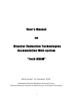
1
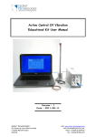
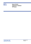
LSPS35XS Piezo Motorized Stage User Manual Version : 1.1.0 CAUTION: READ BEFORE OPENING For safety purposes these instructions must be read before use of this product. Piezoelectric products are not warranted against mechanical damage resulting from improper use, wherein excessive forces or voltages that are outside specified ranges are applied. High voltage is present in this product. Only qualified personnel should work on or around this equipment and only after becoming thoroughly familiar with all warnings, safety notices, and procedures contained herein. The successful and safe operation of this equipment is dependent on proper handling, installation and operation. A "qualified person" is one who is familiar with the installation, construction and operation of the equipment and the hazards involved. In addition, he/she has the following qualifications: is trained and authorized to energize, de-energize, clean, and ground equipment in accordance with established practices, is trained in the proper care and use of protective equipment in accordance with established safety practices. CEDRAT TECHNOLOGIES 59, Chemin du Vieux Chêne - Inovallée F-38246 MEYLAN Cedex FRANCE 2 URL: http://www.cedrat-technologies.com Email: [email protected] Phone: +33 (0)4 56 58 04 00 Fax: +33 (0)4 56 58 04 01 Table of Contents 1. General ............................................................................................................ 5 2. Stepping Piezo Actuator Principle................................................................... 6 3. The LSPS35XS and its controlling board SPC45............................................... 9 3.1. LSPS35XS description ............................................................................... 9 3.1.1. Overall ............................................................................................... 9 3.1.2. Mechanical interfaces ..................................................................... 10 3.1.3. Electrical interfaces ......................................................................... 10 3.1.4. Incremental magnetic sensor ......................................................... 11 3.2. SPC45 description................................................................................... 11 3.3. LSPS35XS performances ......................................................................... 14 4. Environment compatibilities ......................................................................... 15 5. Graphical User Interface ............................................................................... 16 5.1. 5.1.1. Required equipments ..................................................................... 16 5.1.2. First time installation ...................................................................... 16 5.2. Overall description ................................................................................. 18 5.2.1. Communication ............................................................................... 19 5.2.2. Load configuration .......................................................................... 21 5.2.3. Mode choice ................................................................................... 23 5.2.4. System Feedback ............................................................................ 25 5.2.5. Signal definition .............................................................................. 25 5.2.6. Missing sensor................................................................................. 26 5.3. 6. Software Installation .............................................................................. 16 Operating the system without GUI ........................................................ 26 Operation of the SPC45 ................................................................................ 27 6.1.1. Procedure:....................................................................................... 27 CEDRAT TECHNOLOGIES 59, Chemin du Vieux Chêne - Inovallée F-38246 MEYLAN Cedex FRANCE 3 URL: http://www.cedrat-technologies.com Email: [email protected] Phone: +33 (0)4 56 58 04 00 Fax: +33 (0)4 56 58 04 01 7. Expert mode .................................................................................................. 30 7.1. System command signal definition ........................................................ 30 7.2. Define Bounds ........................................................................................ 32 7.3. Closed-loop max error............................................................................ 32 7.4. Other incremental sensor integration ................................................... 33 7.5. “Load” of “Save” Configuration ............................................................. 34 8. Trouble Shooting Form ................................................................................. 35 9. Warranty Conditions and exceptions ........................................................... 41 10. Inspection upon receipt ............................................................................. 42 11. Notes .......................................................................................................... 43 CEDRAT TECHNOLOGIES 59, Chemin du Vieux Chêne - Inovallée F-38246 MEYLAN Cedex FRANCE 4 URL: http://www.cedrat-technologies.com Email: [email protected] Phone: +33 (0)4 56 58 04 00 Fax: +33 (0)4 56 58 04 01 1. GENERAL Piezoelectric Actuators from CEDRAT TECHNOLOGIES SA consists in a wide range of actuators, divided in four categories: Multilayer actuators, that are not mechanically prestressed, Parallel prestressed actuators, that are mechanically prestressed multilayer actuators and offer mechanical interfaces, Amplified piezo actuators, which use an elastic amplifier to both prestress the multilayer actuator and amplify the displacement. Piezoelectric Motor, using Cedrat Technologies actuators to perform millimetric stroke. Piezoelectric Actuators must be handled carefully. Lifetime of Piezoelectric Multilayer actuators is not limited by wear. They can perform millions of cycles without loss of performance provided they are operated under suitable conditions. The lifetime of a Piezoelectric Multilayer Actuators is a function of many combined parameters; the most influencing being the applied voltage, the temperature and the humidity. For maximum lifetime, operating voltage should be minimized, especially when they are used in static conditions. CEDRAT TECHNOLOGIES 59, Chemin du Vieux Chêne - Inovallée F-38246 MEYLAN Cedex FRANCE 5 URL: http://www.cedrat-technologies.com Email: [email protected] Phone: +33 (0)4 56 58 04 00 Fax: +33 (0)4 56 58 04 01 2. STEPPING PIEZO ACTUATOR PRINCIPLE Stepping Piezoelectric Actuators are classified as Inertial Stepping Motors (ISM). These motors have the particularity to be based on a single actuator, making the electronic command and control easier. Stepping Piezoelectric Actuators (SPA) are formed of only four parts (Figure 1): the well-established Amplified Piezoelectric Actuator (APA®), a front mass, a clamp and a rod. Rod Clamp APA ® Mass Figure 1 SPA30uXS components SPA operates by accumulation of small steps, using inertial mode, impact forces and stick-slip effects: Typically, a slow APA® actuation generates a slow motion of the mass while the rod sits in the clamp. A fast APA® actuation induces a fast motion of the rod slipping in the clamp. This allows getting steps, which gives a long stroke, called the stepping mode (M1). Between each step the actuator stays naturally locked in position. Figure 2 shows the stepping mode principle for fixed clamp and fixed mass configurations. The load can be fixed on different positions leading to two different motor capabilities thanks to different modes. In a first configuration offering nano positioning, the load can replace the mass or can be fixed to the mass. So when the long stroke (M1) is performed, the motor can be also operated in a deformation mode (M2) for a fine adjustment. In this case, the stroke is proportional to the applied voltage, which leads to a nanometre resolution and a high bandwidth (limited by motor blocked force). In a second configuration, the load is fixed on the moving rod. In this case, the advantage is a high stiffness, but fine mode is no more available. CEDRAT TECHNOLOGIES 59, Chemin du Vieux Chêne - Inovallée F-38246 MEYLAN Cedex FRANCE 6 URL: http://www.cedrat-technologies.com Email: [email protected] Phone: +33 (0)4 56 58 04 00 Fax: +33 (0)4 56 58 04 01 The proposed kit uses as standard configuration the fixed mass configuration. However, developers have the possibility to experiment the other configuration using the “Extracted configuration” Figure 2 Working principles for 2 different configurations The long stroke stepping mode (M1) is produced by step accumulation with an appropriate 0-150V voltage pattern. The short stroke deformation mode (M2) is produced by deformation of the APA®, which is simply proportional to the voltage excitation between –20 to +150V. Only one amplifier channel per SPA is required. Figure 3 SPA stepping mode (M1) and deformation mode (M2) Compared to a piezo stack of the same size, an APA presents a typically 20 to 100 times larger compliance and a four to ten times larger stroke. The larger compliance of the APA leads to a 5 to 10 lower resonance frequency (at constant CEDRAT TECHNOLOGIES 59, Chemin du Vieux Chêne - Inovallée F-38246 MEYLAN Cedex FRANCE 7 URL: http://www.cedrat-technologies.com Email: [email protected] Phone: +33 (0)4 56 58 04 00 Fax: +33 (0)4 56 58 04 01 mass) and so a 5 to 10 times smaller current demand than the same piezo capacitance in a stack. The large deformation stroke of the APA is also an advantage. It provides a useful deformation stroke mode (M2). It also contributes in getting good speed in long stroke mode (M1): larger steps per cycle compensate a lower step frequency. CEDRAT TECHNOLOGIES 59, Chemin du Vieux Chêne - Inovallée F-38246 MEYLAN Cedex FRANCE 8 URL: http://www.cedrat-technologies.com Email: [email protected] Phone: +33 (0)4 56 58 04 00 Fax: +33 (0)4 56 58 04 01 3. THE LSPS35XS AND ITS CONTROLLING BOARD SPC45 The LSPS35XS is a one axis linear stage. It includes a motor LSPA35XS, a linear guiding and a 1.95µm resolution position sensor. The controller is the SPC45 board. The SPC45 controls in closed loop the LSPS35XS and is configurable with a Graphical User Interface (GUI) through a USB plug. The input command can be done with the GUI or with an analogical signal (0..5V) Sensor Feedback Power Input GUI LABVIEW® Figure 4 Synoptic of the control of the LSPS35XS 3.1. LSPS35XS DESCRIPTION 3.1.1. Overall The LSPS35XS works on the principle of the LSPA motor. The amplified piezo actuator used is the APA35XS. The APA35XS is a standard and proven actuator from Cedrat Technologies. CEDRAT TECHNOLOGIES 59, Chemin du Vieux Chêne - Inovallée F-38246 MEYLAN Cedex FRANCE 9 URL: http://www.cedrat-technologies.com Email: [email protected] Phone: +33 (0)4 56 58 04 00 Fax: +33 (0)4 56 58 04 01 Figure 5 APA35XS A stage LSPS35XS has one axis of motion. A linear rail limits the parasitic displacements in other directions and protects the system from external torques and forces. A linear position sensor is also integrated. It has a resolution of 1.95µm and a range of 10mm. 3.1.2. Mechanical interfaces The mechanical interfaces of the LSPS35XS are given below. Figure 6 Mechanical interfaces of the LSPS35XS 3.1.3. Electrical interfaces The LSPS35XS is provided with an 8 pins connector. The function of each pin is given in figure 8 CEDRAT TECHNOLOGIES 59, Chemin du Vieux Chêne - Inovallée F-38246 MEYLAN Cedex FRANCE 10 URL: http://www.cedrat-technologies.com Email: [email protected] Phone: +33 (0)4 56 58 04 00 Fax: +33 (0)4 56 58 04 01 GND Use GUI to reset or V+ Actuator evaluate signal GND frequency changes 5V needed. Channel A Channel B Analogue order Z index (not used) GND input Figure 7 Electrical interfaces of the LSPS35XS 3.1.4. Incremental magnetic sensor The integrated incremental magnetic sensor gives the possibility to reach a 1.95µm resolution in motion. The sensor is powered with a 5V voltage. Two output TTL channels (Channel A and B) are available in order to be decoded to produce a count up pulse or a count down pulse. The decoding operation is done by the proposed driver SPC45 (see §7.4). 3.2. SPC45 DESCRIPTION The Stepping Piezo Controller SPC45 is the driver board of the SPS35XS. It includes control functions, digital and analogue interfaces, and serial communication ports. The SPC45 is powered with the provided standard AC/DC adapter (24Vdc). Description of the SPC45 interfaces is given in Figure 9. WARNING! Be careful when plugging a cable to the SPC45 board. Connection of the input cable to the output connector (or reciprocally) could lead to severe CEDRAT TECHNOLOGIES 59, Chemin du Vieux Chêne - Inovallée F-38246 MEYLAN Cedex FRANCE 11 URL: http://www.cedrat-technologies.com Email: [email protected] Phone: +33 (0)4 56 58 04 00 Fax: +33 (0)4 56 58 04 01 damaging of the electronics. Always verify your connections before switching on the electronics. Output (to SPS35XS) USB Power switch Analogue Input Power input AC/DC converter Figure 8 SPC45 description Input and output of the board are physically given in Figure 9 and Figure 10 and detailed on Table 1. CEDRAT TECHNOLOGIES 59, Chemin du Vieux Chêne - Inovallée F-38246 MEYLAN Cedex FRANCE 12 URL: http://www.cedrat-technologies.com Email: [email protected] Phone: +33 (0)4 56 58 04 00 Fax: +33 (0)4 56 58 04 01 GND V+ Actuator GND 5V Analogue order input Channel A GND Channel B Sensor position feedback Not used GND Negative direction GND 5V Positive Direction GND Figure 10 Output connector details Figure 9 Input connector details Number IN08 IN07 IN06 IN05 IN04 IN03 IN02 IN01 OUT01 OUT02 OUT03 OUT04 OUT05 OUT06 OUT07 OUT08 Description Analogue order input GND Sensor position feedback GND Negative 5V Positive GND Range [0 : 5 ] V [0 : 5 ] V TTL (0 or 5V) TTL (0 or 5V) - Nature In Out In Out In - GND Actuator V+ Actuator GND Actuator 5V Channel A Channel B Z index GND sensor [0 : 110 ] V TTL (0 or 5V) TTL (0 or 5V) TTL (0 or 5V) - Out Out In In Not used - Table 1 SPC45 port description Please notice that connector reference are the following one: ERNI 8b RA 1,27 Cables used are cables 1,27 mm ERNI Minibridge, 8 points. CEDRAT TECHNOLOGIES 59, Chemin du Vieux Chêne - Inovallée F-38246 MEYLAN Cedex FRANCE 13 URL: http://www.cedrat-technologies.com Email: [email protected] Phone: +33 (0)4 56 58 04 00 Fax: +33 (0)4 56 58 04 01 3.3. LSPS35XS PERFORMANCES The performances presented in the following table are results of tests performed with no load, in lab conditions. Additional payload may have consequences on performances. CEDRAT TECHNOLOGIES 59, Chemin du Vieux Chêne - Inovallée F-38246 MEYLAN Cedex FRANCE 14 URL: http://www.cedrat-technologies.com Email: [email protected] Phone: +33 (0)4 56 58 04 00 Fax: +33 (0)4 56 58 04 01 4. ENVIRONMENT COMPATIBILITIES Stepping Piezo Actuator has a few heritages from various environment compatibilities. Vacuum compatibility can be achieved via some precautions, with or without sensor. CEDRAT TECHNOLOGIES 59, Chemin du Vieux Chêne - Inovallée F-38246 MEYLAN Cedex FRANCE 15 URL: http://www.cedrat-technologies.com Email: [email protected] Phone: +33 (0)4 56 58 04 00 Fax: +33 (0)4 56 58 04 01 5. GRAPHICAL USER INTERFACE The Graphical User Interface (GUI) is built to give the user the opportunity to control the system, in open or closed-loop, but also to give feedback about system state. 5.1. SOFTWARE INSTALLATION This paragraph describes the different instructions to connect the SPC45 driver and to install the software. Do not connect the USB driver on the PC before installing the software. The installation is simple: Updated software SPC45 may be downloaded from Cedrat Technologies website. Please check: http://www.cedrat-technologies.com/en/mechatronic-products/softdownload.html It includes the installation of the drivers to dialogue with the SPC45 and the installer for the application software. It contains the autonomous application too. 5.1.1. Required equipments You must install the Software on the following Personal Computer configuration: Change “,” in “.” in the regional configuration of your PC if it is not the case. (Settings/ Controls Panel / Regional and language Options / Customize / Decimal symbol). Software is optimized for 1600x900 screen resolution. 5.1.2. First time installation The operator has to run the “setup.exe”, following the given instructions. CEDRAT TECHNOLOGIES 59, Chemin du Vieux Chêne - Inovallée F-38246 MEYLAN Cedex FRANCE 16 URL: http://www.cedrat-technologies.com Email: [email protected] Phone: +33 (0)4 56 58 04 00 Fax: +33 (0)4 56 58 04 01 Figure 11 Destination directory Figure 12 License Agreement Figure 13 Starting Installation CEDRAT TECHNOLOGIES 59, Chemin du Vieux Chêne - Inovallée F-38246 MEYLAN Cedex FRANCE 17 URL: http://www.cedrat-technologies.com Email: [email protected] Phone: +33 (0)4 56 58 04 00 Fax: +33 (0)4 56 58 04 01 Figure 14 Installation finish After this installation is finished, another driver is installed automatically. The system shall be restarted. Connect your PC with the SPC45 by USB cable and power on the driver. Now the operator can run the software “SPC45.exe” 5.2. OVERALL DESCRIPTION The control software interface is made of a few boxes. The first one concerns the choice of the working mode of the system. Some modes need additional parameters definition, which are detailed further. The second box corresponds to the parameters feedback from the system, and especially position. The communication channel is automatically detected when the software starts. CEDRAT TECHNOLOGIES 59, Chemin du Vieux Chêne - Inovallée F-38246 MEYLAN Cedex FRANCE 18 URL: http://www.cedrat-technologies.com Email: [email protected] Phone: +33 (0)4 56 58 04 00 Fax: +33 (0)4 56 58 04 01 Figure 15 Graphical User Interface SPC45 5.2.1. Communication Before running the GUI, please plug the SPC45 driver, power it and connect the driver to the computer using provided USB cable. The port COM is automatically detected by the software. If the communication is well established, the Running indicator turns green. If the driver is not available, not plugged, or not powered, the communication fails and status indicates “offline”. An additional warning message appears (Figure 16). CEDRAT TECHNOLOGIES 59, Chemin du Vieux Chêne - Inovallée F-38246 MEYLAN Cedex FRANCE 19 URL: http://www.cedrat-technologies.com Email: [email protected] Phone: +33 (0)4 56 58 04 00 Fax: +33 (0)4 56 58 04 01 Figure 16 Waiting message Figure 17 Communication error If this problem occurs, you have to restart the software ensuring to connect the USB cable correctly and to power ON the SPC45 before launching the SPC45.exe. CEDRAT TECHNOLOGIES 59, Chemin du Vieux Chêne - Inovallée F-38246 MEYLAN Cedex FRANCE 20 URL: http://www.cedrat-technologies.com Email: [email protected] Phone: +33 (0)4 56 58 04 00 Fax: +33 (0)4 56 58 04 01 5.2.2. Load configuration The Graphical User Interface SPC45.exe can be used for several products from Cedrat Technologies. Consequently, it is needed to load the default configuration for of your system item. For that, go into the “Expert” mode: Click “OK” on the warning message Click on “Load”: CEDRAT TECHNOLOGIES 59, Chemin du Vieux Chêne - Inovallée F-38246 MEYLAN Cedex FRANCE 21 URL: http://www.cedrat-technologies.com Email: [email protected] Phone: +33 (0)4 56 58 04 00 Fax: +33 (0)4 56 58 04 01 Select and Open the file “xxxxConfigDefault” corresponding to your product: The GUI is now configured for your product. Leave the expert mode by clicking back on “Basic”: CEDRAT TECHNOLOGIES 59, Chemin du Vieux Chêne - Inovallée F-38246 MEYLAN Cedex FRANCE 22 URL: http://www.cedrat-technologies.com Email: [email protected] Phone: +33 (0)4 56 58 04 00 Fax: +33 (0)4 56 58 04 01 The GUI is ready to be used with your product. 5.2.3. Mode choice The user interface allows the user to choose the working mode. Each of them is detailed further. Figure 18 Mode choice 5.2.3.1.Mode 1: Open-loop: Analogue input Especially designed for demo purpose, this mode allows using two TTL (0-5V) inputs, in order to control the direction of the system motion. Please refer to Figure 16 to see input positions (Positive and Negative direction). 5.2.3.2.Mode 2: Open-loop: Number of steps order This mode gives the possibility to send to the system an order as a specific number of steps in the chosen direction. The software updates and monitors automatically the position feedback. CEDRAT TECHNOLOGIES 59, Chemin du Vieux Chêne - Inovallée F-38246 MEYLAN Cedex FRANCE 23 URL: http://www.cedrat-technologies.com Email: [email protected] Phone: +33 (0)4 56 58 04 00 Fax: +33 (0)4 56 58 04 01 Figure 19 Direction and number of step definition Enter Number of desired Steps, select direction and Run the motion. After the motion, the position feedback is automatically updated (see §5.2.4). 5.2.3.3. Mode 3: Closed-loop: Analogue position The “Closed-loop Analogue position” mode is available when a sensor is detected by the driver SPC45. This detection is done when the driver is turned on. If sensor is not detected, the Red LED on SPC45 driver lights. The input range is [0 ; 5] V. The system automatically reaches the desired position. Figure 20 Digital closed-loop order 5.2.3.4.Mode 4: Closed-loop: Digital position The “Closed-loop Digital order” mode is only available when a sensor is detected by the driver SPC45. This detection is done when the driver is turned on. If sensor is not detected, the Red LED on SPC45 driver lights. The desired position (µm) is selected using the input bar cursor or the Digital control. Then run the system motion using RUN button. The Position feedback (µm) is automatically updated after the motion. CEDRAT TECHNOLOGIES 59, Chemin du Vieux Chêne - Inovallée F-38246 MEYLAN Cedex FRANCE 24 URL: http://www.cedrat-technologies.com Email: [email protected] Phone: +33 (0)4 56 58 04 00 Fax: +33 (0)4 56 58 04 01 Figure 21 Closed-loop interface If Mode 4 is the only mode unavailable, please refer to § 5.1.1 to change regional configuration. 5.2.4. System Feedback The user interface gives a feedback. This includes the position and driver temperature. During “Open-loop: Analogue input” mode and “Closed-loop: Analogue order” mode, system status update is done 5 times per second. This would also update values from Maintenance sheet (see §8). 5.2.5. Signal definition The signal definition box (#3) is composed of two buttons. The first one, called “Signal scan”, allows the driver to look for a convenient input signal. This is done automatically, and takes a few seconds. If closed-loop mode is used, the system takes place to the previous position order as soon as the “Signal scan” is finished. CEDRAT TECHNOLOGIES 59, Chemin du Vieux Chêne - Inovallée F-38246 MEYLAN Cedex FRANCE 25 URL: http://www.cedrat-technologies.com Email: [email protected] Phone: +33 (0)4 56 58 04 00 Fax: +33 (0)4 56 58 04 01 Note that this function may not give useful feedback, especially if loading is not correct and/or mechanical stops are strongly involved. Load the default configuration if the system seems to be inefficient after the Signal Scan. (§5.2.2) Figure 22 Signal definition box 5.2.6. Missing sensor If you are not using the provided sensor, or if there is connection problem, the SPC45 driver is not able to return position feedback from sensor. The GUI indicates a “sensor missing” message, next to the Position feedback indicator. Figure 23 Sensor status 5.3. OPERATING THE SYSTEM WITHOUT GUI Mode 1 and 3 (Analogue modes) are fully usable without GUI. For other modes: the SPC45 driver is commanded using serial digital inputs. Listing of the serial commands needed to communicate with the SPC45 driver may be furnished. Please contact us to get further information. CEDRAT TECHNOLOGIES 59, Chemin du Vieux Chêne - Inovallée F-38246 MEYLAN Cedex FRANCE 26 URL: http://www.cedrat-technologies.com Email: [email protected] Phone: +33 (0)4 56 58 04 00 Fax: +33 (0)4 56 58 04 01 6. OPERATION OF THE SPC45 USB Computer SCP45 Power Motor Figure 24 Standard configuration 6.1.1. Procedure: (01) Check the content of the delivery If any component is missing, please contact Cedrat Technologies. (02) Plug the SPC45 driver to the motor platform using the provided standard cable. (03) Plug the SPC45 driver to a computer using the provided USB cable. CEDRAT TECHNOLOGIES 59, Chemin du Vieux Chêne - Inovallée F-38246 MEYLAN Cedex FRANCE 27 URL: http://www.cedrat-technologies.com Email: [email protected] Phone: +33 (0)4 56 58 04 00 Fax: +33 (0)4 56 58 04 01 (04) Plug the power adapter to the driver SPC45. Turn on the Power switch. (05) Launch SPC45.exe. Please refer to § 5.1 to get information about software installation. (06) Wait for the communication between the computer and the driver is settled. (07) Choose the desired control mode (Open-loop - Number of steps order OR Closed-loop – Digital order). Note that the two other modes are unusable without analogue input, so they are not convenient in “plug-and-play” configuration. CEDRAT TECHNOLOGIES 59, Chemin du Vieux Chêne - Inovallée F-38246 MEYLAN Cedex FRANCE 28 URL: http://www.cedrat-technologies.com Email: [email protected] Phone: +33 (0)4 56 58 04 00 Fax: +33 (0)4 56 58 04 01 (08) Please refer to § 5.2.3.2 and § 5.2.3.4 to obtain information about these modes way-of-working. Figure 25 Software interface CEDRAT TECHNOLOGIES 59, Chemin du Vieux Chêne - Inovallée F-38246 MEYLAN Cedex FRANCE 29 URL: http://www.cedrat-technologies.com Email: [email protected] Phone: +33 (0)4 56 58 04 00 Fax: +33 (0)4 56 58 04 01 7. EXPERT MODE This part details information about possibilities offered to expert, who wants to dedicate the system configuration to their own application. By the way, expert may adapt the system to fit their own mechanism specification. Do not try to change any of the following parameters if you are not sure to use the system in the correct way. All of the possibilities described here are accessible by activating the “Expert Mode” tab on the GUI. When clicking on it, the following message informs you to refer to this part of the User’s Manual. 7.1. SYSTEM COMMAND SIGNAL DEFINITION The LSPA and LSPS systems are using a specific waveform to generate the motion. This waveform has been settled to allow users to load the system with small loadings. For other loadings, “Signal Scan” function (see §5.2.5) allows driver SPC45 to look for an adapted input signal. However, expert may manually improve the signal definition to improve system performances. The user interface gives the expert the possibility to change the parameters of the system input signal. The main rule of the frequency change is explained by Figure 27. With load, the optimal frequency decreases. According to user’s payload, the signal frequency may have to be changed. CEDRAT TECHNOLOGIES 59, Chemin du Vieux Chêne - Inovallée F-38246 MEYLAN Cedex FRANCE 30 URL: http://www.cedrat-technologies.com Email: [email protected] Phone: +33 (0)4 56 58 04 00 Fax: +33 (0)4 56 58 04 01 Stage speed Increasing stage loading Signal frequency Figure 26 Example of signal frequency influence on speed for several loadings The Graphical User Interface allows to impact on the signal frequency. It consists in indicating directly the desired signal frequency to the controller. Two others parameters accessible are Duty cycle for each direction. Figure 28 shows the impact of signal duty-cycle variation on system speed. It can be seen that optimal values are reached for approximately 35% and 70%. These values Stage speed are set as default values. 10 20 30 40 50 60 70 80 90 Signal Duty-cycle Figure 27 Duty-cycle influence principle on system speed The user interface is presented in Figure 29 CEDRAT TECHNOLOGIES 59, Chemin du Vieux Chêne - Inovallée F-38246 MEYLAN Cedex FRANCE 31 URL: http://www.cedrat-technologies.com Email: [email protected] Phone: +33 (0)4 56 58 04 00 Fax: +33 (0)4 56 58 04 01 Figure 28 Signal Expert definition 7.2. DEFINE BOUNDS It is possible to define numeric bounds for the system. This option can be used in order to limit the motion of the system in a given window. The bounds will only be taken into account in “Mode 4 – Cloased loop – Digital Order” 7.3. CLOSED-LOOP MAX ERROR WARNING! Changing the value of the maximum positioning error might lead to unstable control. The closed-loop mode is done by an on/off control. While the error, defined as the difference between the position order and the position feedback is bigger than the max error, motion is performed. Figure 30(a) explains this principle. CEDRAT TECHNOLOGIES 59, Chemin du Vieux Chêne - Inovallée F-38246 MEYLAN Cedex FRANCE 32 URL: http://www.cedrat-technologies.com Email: [email protected] Phone: +33 (0)4 56 58 04 00 Fax: +33 (0)4 56 58 04 01 (a) Max error (b) Order Unstable position Motor position Figure 29 Closed-loop principle and instability risk The main drawback of this control solution is the instability created by the discrete behaviour of the controller. Indeed, once the maximum error is below standard step size, the system may have major difficulties to reach the desired position. Figure 29 (b) presents an example of this situation. The maximum error may be changed using the following cursor (see figure 31), available at the front panel of the Expert tab. Figure 30 Max error setting 7.4. OTHER INCREMENTAL SENSOR INTEGRATION WARNING! When the sensor is changed, if the closed-loop control is unstable or direction of motion reversed, this might result from the inversion of the channels. Swap the channels connections and try again. The driver SPC45 allows interacting with any incremental sensor, using two 5VTTL-Logic signals. Provided sensor gets a 1.95 µm resolution. This gain, defined as the standard value is visible on the GUI (see fig 32). It has no reason to be changed as long as the provided sensor is used. CEDRAT TECHNOLOGIES 59, Chemin du Vieux Chêne - Inovallée F-38246 MEYLAN Cedex FRANCE 33 URL: http://www.cedrat-technologies.com Email: [email protected] Phone: +33 (0)4 56 58 04 00 Fax: +33 (0)4 56 58 04 01 Figure 31 Sensor resolution setting However, user’s test bench may already have its own incremental sensor. In this case, sensor resolution can be changed in order to fit considered sensor resolution. 7.5. “LOAD” OF “SAVE” CONFIGURATION It is possible to load or save a given configuration thanks to the buttons “Load” and “Save”. CEDRAT TECHNOLOGIES 59, Chemin du Vieux Chêne - Inovallée F-38246 MEYLAN Cedex FRANCE 34 URL: http://www.cedrat-technologies.com Email: [email protected] Phone: +33 (0)4 56 58 04 00 Fax: +33 (0)4 56 58 04 01 8. TROUBLE SHOOTING FORM Error diagnostic may be helped using the following graphs. Please identify your problem and refer to associated protocol. Problem The system doesn’t move when motion is requested Protocol 0 The system moves but not correctly 1 Communication with the SPC45 driver is not working 2 My problem is not fixed 3 For advanced debugging, Maintenance Tab includes information about SPC45. This Tab is locked by a password. Please contact Cedrat Technologies if you meet problems and want to unlock this Tab. CEDRAT TECHNOLOGIES 59, Chemin du Vieux Chêne - Inovallée F-38246 MEYLAN Cedex FRANCE 35 URL: http://www.cedrat-technologies.com Email: [email protected] Phone: +33 (0)4 56 58 04 00 Fax: +33 (0)4 56 58 04 01 0 Stage doesn’t move when Make Power available motion is requested Go to 0 No Green LED is No Switch is turned lighting No Yes plugged Yes Driver is powered Red LED is SPC45 driver is OFF No Yes Power is available Yes Switch ON Plug the SPC45 driver Go to 0 Go to 0 Contact Cedrat Technologies Yes lighting No Stage plateform No Connect the platform Go to 0 is connected Yes Motor produces No Use GUI to reset setting Go to 3 if not fixed noise Yes Loading and/or frequency No have been changed Use GUI to reset setting Go to 3 if not fixed ostic Yes Use GUI to reset or evaluate signal frequency changes needed. CEDRAT TECHNOLOGIES 59, Chemin du Vieux Chêne - Inovallée F-38246 MEYLAN Cedex FRANCE 36 URL: http://www.cedrat-technologies.com Email: [email protected] Phone: +33 (0)4 56 58 04 00 Fax: +33 (0)4 56 58 04 01 1 The stage moves but not correctly I know the used No mode Connect GUI and settled correct mode Go to 1 Yes I send a correct No Correct order using GUI No Use GUI to reset setting order Yes Loading and/or frequency have been changed Go to 3 if not fixed Yes GND Use GUI to reset or evaluate signal frequency changes needed. CEDRAT TECHNOLOGIES 59, Chemin du Vieux Chêne - Inovallée F-38246 MEYLAN Cedex FRANCE 37 URL: http://www.cedrat-technologies.com Email: [email protected] Phone: +33 (0)4 56 58 04 00 Fax: +33 (0)4 56 58 04 01 2 Communication with the SPC45 driver is not working Driver is powered No Plug and power the SPC45 driver. Check if Green Led is lighting Yes USB cable is connected No Connect USB cable on both sides Yes Another program is using the serial port No Restart Driver (Power off and on) Yes Close the other program and restart GUI CEDRAT TECHNOLOGIES 59, Chemin du Vieux Chêne - Inovallée F-38246 MEYLAN Cedex FRANCE 38 URL: http://www.cedrat-technologies.com Email: [email protected] Phone: +33 (0)4 56 58 04 00 Fax: +33 (0)4 56 58 04 01 3 My problem is not fixed Remove loading from mobile part Plus USB cable and Run GUI Go to Maintenance Tab and clic on “Sweep” Clic on « Sweep DC » Realize a print screen of the GUI Take a photograph of your setting Send everything to Cedrat. Specify serial number of stage and driver and precise problem description. (see next page) CEDRAT TECHNOLOGIES 59, Chemin du Vieux Chêne - Inovallée F-38246 MEYLAN Cedex FRANCE 39 URL: http://www.cedrat-technologies.com Email: [email protected] Phone: +33 (0)4 56 58 04 00 Fax: +33 (0)4 56 58 04 01 If you don’t find the solution to your problem using the proposed trouble shooting form, please contact your vendor with the following information: Product: Please give mention here the references and delivery date, History: Please summarize here every action which has been performed with the device since the delivery, Problem description: Please describe here the problems CEDRAT TECHNOLOGIES 59, Chemin du Vieux Chêne - Inovallée F-38246 MEYLAN Cedex FRANCE 40 URL: http://www.cedrat-technologies.com Email: [email protected] Phone: +33 (0)4 56 58 04 00 Fax: +33 (0)4 56 58 04 01 9. WARRANTY CONDITIONS AND EXCEPTIONS The equipment is warranted for a period of one year from date of shipment, including parts and labor, and only under standard technical conditions as outlined above and expressly mentioned in the technical data sheet. Repairs will be carried out at Cedrat Technologies or through your vendor. During the warranty period, Cedrat Technologies will, at its option, either repair or replace products which prove to be defective. Interventions or attempts to service or repair the Actuators by any unauthorized persons will invalidate this warranty. In addition, this warranty will not apply if the SPS35XS or SPC45 Driver are subjected to any of the following: improper handling, including, but not limited to, shocks and abrasions improper installation, including, but not limited to, excessive mechanical forces and moments, failure to use the standard electrical and mechanical interfaces excessive voltage, including, but not limited to, peak values outside the recommended operating range, DC values applied for excessive time periods inappropriate environmental conditions, including, but not limited to, high temperatures or high humidity CEDRAT TECHNOLOGIES 59, Chemin du Vieux Chêne - Inovallée F-38246 MEYLAN Cedex FRANCE 41 URL: http://www.cedrat-technologies.com Email: [email protected] Phone: +33 (0)4 56 58 04 00 Fax: +33 (0)4 56 58 04 01 10. INSPECTION UPON RECEIPT This product has been inspected and shown to operate correctly at the time of shipment. Immediately upon receipt of the product, it should be inspected carefully for any signs of damage that may have occurred during shipment. If any damage is found, a claim should be filed with the carrier. The package should also be inspected for completeness according to the enclosed packing list. If an order is incorrect or incomplete, contact your distributor. CEDRAT TECHNOLOGIES 59, Chemin du Vieux Chêne - Inovallée F-38246 MEYLAN Cedex FRANCE 42 URL: http://www.cedrat-technologies.com Email: [email protected] Phone: +33 (0)4 56 58 04 00 Fax: +33 (0)4 56 58 04 01 11. NOTES CEDRAT TECHNOLOGIES 59, Chemin du Vieux Chêne - Inovallée F-38246 MEYLAN Cedex FRANCE 43 URL: http://www.cedrat-technologies.com Email: [email protected] Phone: +33 (0)4 56 58 04 00 Fax: +33 (0)4 56 58 04 01