1
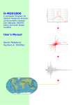
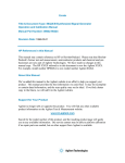
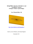
[Type text] 2013 UCSD [USER MANUAL FOR SHAKE91_INPUT] A program designed to interact with Shake91. Shake91_Input formats an input file for Shake91 (Idras & Sun 1993), and is able to applicable figures using the outputted data. John Li Table of Contents 1. Introduction ............................................................................................................................. 5 2. 1.1 Overview .......................................................................................................................... 5 1.2 Getting Started.................................................................................................................. 5 Menu ........................................................................................................................................ 6 2.1 2.1.1 New (Ctrl + N) .......................................................................................................... 6 2.1.2 Open (Ctrl + O) ......................................................................................................... 6 2.1.3 Save (Ctrl + S) .......................................................................................................... 6 2.2 Material Properties ........................................................................................................... 7 2.2.1 Define New Material (Ctrl + D)................................................................................ 8 2.2.2 Modify Existing Material (Ctrl + M) ...................................................................... 11 2.2.3 Use Shear Strength to Define Material (Ctrl + U) .................................................. 14 2.2.4 View Existing Material (Ctrl + E) .......................................................................... 17 2.3 Shake91 .......................................................................................................................... 18 2.3.1 Save Model & Run Analysis (Ctrl + R) .................................................................. 18 2.3.2 Run .......................................................................................................................... 18 2.4 3. File.................................................................................................................................... 6 View ............................................................................................................................... 19 2.4.1 View Figures (Ctrl + F) .......................................................................................... 19 2.4.2 Close All Figures (Ctrl + C) ................................................................................... 19 Creating Shake91 Input File .................................................................................................. 20 3.1 Filename ......................................................................................................................... 20 3.2 Dynamic Soil Properties................................................................................................. 21 3.3 Soil Profile...................................................................................................................... 22 3.3.1 Number of Layers ................................................................................................... 22 3.3.2 #............................................................................................................................... 22 3.3.3 Material ................................................................................................................... 22 3.3.4 Thickness (ft) .......................................................................................................... 22 3.3.5 Shear Modulus (ksf) ................................................................................................ 22 3.3.6 Initial Damping (decimal) ....................................................................................... 22 3.3.7 Unit Weight (ksf) .................................................................................................... 23 2 3.3.8 Vs (ft/sec) ................................................................................................................ 23 3.3.9 Save Acc ................................................................................................................. 23 3.3.10 Outcrop ................................................................................................................... 23 3.4 Input Motion ................................................................................................................... 24 3.4.1 Input Motion ........................................................................................................... 24 3.4.2 Acc Format.............................................................................................................. 24 3.4.3 NV ........................................................................................................................... 24 3.4.4 MA .......................................................................................................................... 24 3.4.5 Max Freq ................................................................................................................. 24 3.4.6 Multi........................................................................................................................ 24 3.4.7 Max Acc .................................................................................................................. 25 3.4.8 dt ............................................................................................................................. 25 3.4.9 # of Header Lines .................................................................................................... 25 3.4.10 Acc Per Line ........................................................................................................... 25 3.4.11 Layer Above Motion ............................................................................................... 25 3.4.12 Outcrop ................................................................................................................... 25 3.5 Amplification Spectrum ................................................................................................. 27 3.5.1 Layer 1 .................................................................................................................... 27 3.5.2 Layer 2 .................................................................................................................... 27 3.5.3 Frequency Step........................................................................................................ 27 3.6 Fourier Spectrum (currently not working) ..................................................................... 29 3.6.1 Layers ...................................................................................................................... 29 3.6.2 Iterations ................................................................................................................. 29 3.6.3 Number of Values to Output ................................................................................... 29 3.7 Response Spectra............................................................................................................ 30 3.7.1 Layers ...................................................................................................................... 30 3.7.2 Damping .................................................................................................................. 30 3.7.3 Gravity .................................................................................................................... 30 3.8 Ratio of Equivalent Uniform Strain to Maximum Strain ............................................... 31 3.8.1 Output Strain ........................................................................................................... 31 3.8.2 Number of Iterations ............................................................................................... 31 3 3.8.3 3.9 Strain Ratio ............................................................................................................. 31 Sublayer for which Shear Stress or Strain are Computed & Saved ............................... 32 3.9.1 Stress ....................................................................................................................... 32 3.9.2 Stress NV ................................................................................................................ 32 3.9.3 Strain ....................................................................................................................... 32 3.9.4 Strain NV ................................................................................................................ 32 4 1. Introduction 1.1 Overview Shake91_Input is a graphical user interface designed to interact with another program called Shake91 (Idras & Sun 1993). Some of the capabilities of Shake91_Input include: Generating and format an input file for Shake91 (Idras & Sun 1993) Storing and modifying material properties for use by Shake91 (Idras & Sun 1993) Plotting the results of the output from Shake91 (Idras & Sun 1993) 1.2 Getting Started Shake91_Input is a Matlab code complied into an executable file. To make use of this program, you need to first install MCR onto your computer. The installer can be found on http://www.soilquake.net/shake91_input/. After having installed MCR you should be able to run Shake91_Input.exe. For an example of how the values should be entered into the Shake91_Input Interface please reference the Default input values and/or the provided examples in this document. 5 2. Menu The Menu Bar contains a majority of the functionality of Shake91_Input. From the menu bar the options File, Material Properties, Shake91, View, and Help can be found, which will be discussed in further detail in the following sections. Figure 1Menu Bar 2.1 File To save and/or open input files for the Shake91_Input, you can use the options that can be found under File as shown in Figure 2. Besides clicking on File and then selecting either New, Open, or Save, you can also make use of the hotkeys as shown below. Figure 2 Submenu for "File" Note: This input file is different than what is used by Shake91 (Idras & Sun 1993) uses and cannot be used directly. (To create a file that Shake91 (Idras & Sun 1993) can use, you can use Save Model & Run Analysis which is located under Shake91 (which can be found in the menu bar), or push Ctrl + R. The Save Model & Run Analysis function will create an input file for Shake91 (Idras & Sun 1993) using the values entered in the Shake91_Input Interface, and then subsequently using the created input file in Shake91. 2.1.1 New (Ctrl + N) This option will load the default Shake91_Input values. 2.1.2 Open (Ctrl + O) This option will open a previously saved file. 2.1.3 Save (Ctrl + S) This option will save the currently entered values in the Shake91_Input Interface. Note: This saved file cannot be used directly with Shake91 (Idras & Sun 1993). 6 2.2 Material Properties To generate, modify, or view materials that can be used to create the input file for Shake91 (Idras & Sun 1993) look under Material Properties. Note 1: The created Material files are stored in the folder called Material. The provided material Clay, Rock, Sand, PI_-_0, PI_-_15, PI_-_30, PI_-_50, PI_-_100, and PI_-_200 cannot be saved over using Shake91_Input. When modifying these materials you will be prompted to change the name, before saving. Note 2: If you do not wish to make use of Shake91_Input to generate these files, you can open any of the files in the Material folder to see how they are formatted. The material generally follows this format: the first row is the header; the second row is the amount of numbers entered for the following column of numbers. The numbers that follow correspond with what is shown in the header. Figure 3 Submenu for “Material Properties” 7 2.2.1 Define New Material (Ctrl + D) To define a new material you can make use of the Define New Material function that is found under Material Properties. When you select this option a window similar to the one shown below should appear. Figure 4 Example inputs for “Define New Material” 2.2.1.1 Enter File Name For this entry input the desired file name. (You will be asked to change the name of the file, if you use the same name as one of the provided materials, such as clay, sand, rock, PI – 0, etc.) Example: Clay2 2.2.1.2 Enter Strain Values (%) for G/Gmax For this entry you would need to enter strain values (%) that will correspond to the Modulus Reduction that are entered in the field below. These values should be entered in order, and as a vector of values as shown below. (The amount of numbers entered for Strain Values should be the same as the amount entered for Modulus Reduction. Additionally, only a maximum of 20 values can be entered.) Example: 0.0001 0.0003 0.001 0.003 0.01 0.03 0.1 0.3 1 3 10 8 2.2.1.3 Modulus Reduction (G/Gmax) For this entry you would need to enter Modulus Reduction values (divided by Gmax) that will correspond to the previously entered strain values. These values should be entered in order, and as a vector of values as shown below. (The amount of numbers entered for Modulus Reduction should be the same as the amount entered for Strain Values. Additionally, only a maximum of 20 values can be entered.) Example: 1 1 1 0.981 0.941 0.847 0.656 0.438 0.238 0.144 0.11 2.2.1.4 Enter Strain Values (%) for damping For this entry you would need to enter strain values (%) that will correspond to the damping that will be entered in the field below. These values should be entered in order, and as a vector of values as shown below. (The amount of numbers entered for Strain Values should be the same as the amount entered for damping. Similar to the two sets of values above, a maximum of 20 values can be entered. The amount of values for damping does not need to be the same as Modulus Reduction.) Example: 0.0001 0.0003 0.001 0.003 0.01 0.03 0.1 0.3 1 3.16 10 2.2.1.5 Damping (%) For this entry you would need to enter damping values (%)) that will correspond to the previously entered strain values. These values should be entered in order, and as a vector of values as shown below. (The amount of numbers entered for damping should be the same as the amount entered for strain. Similar to the two sets of values above a maximum of 20 values can be entered. The amount of values for damping does not need to be the same as Modulus Reduction.) Example: 0.24 0.42 0.8 1.4 2.8 5.1 9.8 15.5 21 25 28 9 After you finish entering values and clicking ok, a window will pop up that will plot the entered values. Besides the three figures, you will be asked if you want to save the material you just defined, or if you want to keep modifying the material. Clicking yes will save the material using the file name entered previously. If you already have a file with the given name you will be asked if you want to save over it. You cannot save over the materials that came with the program. Figure 5 Example Using “Define New Material” 10 2.2.2 Modify Existing Material (Ctrl + M) To modify an existing material you can make use of the Modify Existing Material function that is found under Material Properties. When you select this option you will be prompt to select one of the available materials, which can be one that was provided with the program, or one you have previously defined. After selecting a material a window similar to figure below will popup. To modify the material you can simply change the numbers to what you want, or even add more if there are fewer than 20 values for any given entry. Note: Make sure the amount of values entered for Modulus Reduction and Damping is the same as the corresponding Strain Values if you are going to enter or delete values. Figure 6 Example inputs for “Modifying Existing Material” 2.2.2.1 Enter File Name For this entry input the desired file name. (You will be asked to change the name of the file if you use the same name as one of the provided materials, such as clay, sand, rock, PI – 0, etc.) Example: Clay2 11 2.2.2.2 Enter Strain Values (%) for G/Gmax For this entry you would need to enter strain values (%) that will correspond to the Modulus Reduction that will be entered in the field below. These values should be entered in order, and as a vector of values as shown below. (The amount of numbers entered for Strain Values should be the same as the amount entered for Modulus Reduction. Additionally, only a maximum of 20 values can be entered.) Example: 0.0001 0.0003 0.001 0.003 0.01 0.03 0.1 0.3 1 3 10 2.2.2.3 Modulus Reduction (G/Gmax) For this entry you would need to enter Modulus Reduction values (divided by Gmax) that will correspond to the previously entered strain values. These values should be entered in order, and as a vector of values as shown below. (The amount of numbers entered for Modulus Reduction should be the same as the amount entered for Strain Values. Additionally, only a maximum of 20 values can be entered.) Example: 1 1 1 0.99 0.95 0.86 0.6 0.4 0.22 0.13 0.09 2.2.2.4 Enter Strain Values (%) for damping For this entry you would need to enter strain values (%) that will correspond to the damping that will be entered in the field below. These values should be entered in order, and as a vector of values as shown below. (The amount of numbers entered for Strain Values should be the same as the amount entered for damping. Similar to the two sets of values above a maximum of 20 values can be entered. The amount of values for damping does not need to be the same as Modulus Reduction.) Example: 0.0001 0.0003 0.001 0.003 0.01 0.03 0.1 0.3 1 3.16 10 2.2.2.5 Damping (%) For this entry you would need to enter damping values (%)) that will correspond to the previously entered strain values. These values should be entered in order, and as a vector of values as shown below. (The amount of numbers entered for damping should be the same as the amount entered for strain. Similar to the two sets of values above a maximum of 20 values can be entered. The amount of values for damping does not need to be the same as Modulus Reduction.) Example: 0.25 0.5 1 2 3 5 8 16 22 25 30 12 After you finish entering values and clicking ok, a window will pop up that will plot the entered values. The plot shows both the original, as well as the modified curve. Besides the three figures, you will be asked if you want to save the material you just defined, or if you want to keep modifying the material as shown in the figure below. Clicking yes will save the material using the file name entered previously. If you already have a file with the given name you will be asked if you want to save over it. You cannot save over the materials that came with the program. Figure 7 Example using “Modify Existing Material” 13 2.2.3 Use Shear Strength to Define Material (Ctrl + U) Besides using Modify Existing Material function, you can also use Use Shear Strength to Define Material as well. (This option can be found under Material Properties.) When you select this option you will be prompt to select one of the available materials which can be one that was provided with the program, or one you have previously defined. After selecting a material a window similar to the figure below will popup. To modify the material you can simply change the numbers to what you want, or even add more if there are fewer than 20 values for any given entry. (Make sure the amount of values entered for Shear Stress and Damping is the same as the corresponding Strain Values, if you are going to enter or delete values.) For Shear Strength only a single value should be entered. The last value will be set to equal the shear strength, and adjust the last few values to reach the entered shear strength. Figure 8 Example inputs for “Use Shear Strength to Define Material” 2.2.3.1 Enter File Name For this entry input the desired file name. (You will be asked to change the name of the file if you use the same name as one of the provided materials, such as clay, sand, rock, PI – 0, etc.) Example: Clay2 14 2.2.3.2 Enter Strain Values (%) for Shear For this entry you would need to enter strain values (%) that will correspond to the Modulus Reduction that will be entered in the field below. These values should be entered in order, and as a vector of values as shown below. (The amount of numbers entered for Strain Values should be the same as entered for Modulus Reduction. Additionally, only a maximum of 20 values can be entered.) Example: 0.0001 0.0003 0.001 0.003 0.01 0.03 0.1 0.3 1 3 10 2.2.3.3 Enter Shear Stress Values (/Gmax, the last value will be set to equal the Shear Strength set below) For this entry you would need to enter Shear Stress values (divided by Gmax) that will correspond to the previously entered strain values. These values should be entered in order, and as a vector of values as shown below. (The amount of numbers entered for Shear Stress should be the same as entered for Strain Values. Additionally, only a maximum of 20 values can be entered.) Example: 1e-006 3e-006 1e-005 0.001314 0.00238 0.00432 0.011 2.943e-005 9.41e-005 0.0002541 0.000656 2.2.3.4 Enter Shear Strength (one value and divided by Gmax, this value controls the last few values for Shear Stress) For this entry you need to enter a single value, which will adjust the last few values entered for Shear Stress. Note: The last value for Shear Stress will be set equal to the Shear Strength, and if necessary the last few numbers will be adjusted. Example: 0.014 2.2.3.5 Enter Strain Values (%) for damping For this entry you would need to enter strain values (%) that will correspond to the damping that will be entered in the field below. These values should be entered in order, and as a vector of values as shown below. (The amount of numbers entered for Strain Values should be the same as entered for damping. Similar to the two sets of values above a maximum of 20 values can be entered. The amount of values for damping does not need to be the same as for Modulus Reduction.) Example: 0.0001 0.0003 0.001 0.003 0.01 0.03 0.1 0.3 1 3.16 10 15 2.2.3.6 Damping (%) For this entry you would need to enter damping values (%)) that will correspond to the previously entered strain values. These values should be entered in order, and as a vector of values as shown below. (The amount of numbers entered for damping should be the same as entered for strain. Similar to the two sets of values above a maximum of 20 values can be entered. The amount of values for damping does not need to be the same as for Modulus Reduction.) Example: 0.24 0.42 0.8 1.4 2.8 5.1 9.8 15.5 21 25 28 After you finish entering values and clicking ok, a window will pop up that will plot the entered values. The plot shows both the original, as well as the modified curve. Besides the three figures, you will be asked if you want to save the material you just defined, or if you want to keep modifying the material as shown in the figure below. Clicking yes will save the material using the file name entered previously. If you already have a file with the given name you will be asked if you want to save over it. You cannot save over the materials that came with the program. Figure 9 Example using “Use Shear Strength to Define Material” 16 2.2.4 View Existing Material (Ctrl + E) To view an existing material you can use the View Existing Material function, which will open open four figures. Three of the figures plot Strain vs. Modulus, Strain vs. Damping and Strain vs. Stress. The last figure lists the values for Strain, Modulus Reduction, Shear Stress, and Damping as shown in the figure below. Figure 10 Example using "View Existing Material" 17 2.3 Shake91 To Interact with Shake91 (Idras & Sun 1993), you can use the options found under Shake91 on the menu bar. Figure 11 Submenu for "Shake91" 2.3.1 Save Model & Run Analysis (Ctrl + R) Utilizing Save Model & Run Analysis will create an input file for Shake91 (Idras & Sun 1993) using the values you have entered in the interface, and then immediately use that input file to run Shake91. Note: This input file is different than the one that Shake91_Interface uses. 2.3.2 Run Runs Shake91 (Idras & Sun 1993) using the input file you have selected. (This option does not run using the inputted values, but rather the rather values from the selected file. After selecting an input file for Shake91 (Idras & Sun 1993) you will be prompted to enter names for the Output files. If there are no problems with running Shake91 using the inputted values, Shake91_Input will subsequently attempt to create figures using the output files generated by Shake91. 18 2.4 View To view the figures that were generated when you used the Save Model & Run Analysis or Run function, you can click View Figures located under View. Figure 12 Submenu for "View" 2.4.1 View Figures (Ctrl + F) To view figures you need to first generate output files from Shake91 (Idras & Sun 1993), which can be done with the Save Model & Run Analysis function located under Shake91 (or you can push Ctrl + R). After selecting this option you will be prompt to select a folder, which are all named after the input files used for Shake91 (Idras & Sun 1993). After selecting the folder it will list out all figures from which you can select which ones to view. 2.4.2 Close All Figures (Ctrl + C) Closes all open figures. 19 3. Creating Shake91 Input File 3.1 Filename To enter a file name, you can change the field on the left corner of the interface as shown below. When generating an input file you will be prompted to change the name if you have not already. Example: Default Figure 13 Highlighting location of “File Name” 20 3.2 Dynamic Soil Properties To select the materials to be used, you can click select and apply, which will open up a list of already defined materials. (You can use the provided material or create your own, using the options under Material Properties). Clicking this button will set the selected material to the number to the left of the button. To change the number you can simply click and change the number that is highlighted on the left of Figure 14. This list of material is referenced to in the second column of Soil Profile. In Soil Profile the second column are all numbers which correspond to the materials in Dynamic Soil Properties. Figure 14 Highlighting location of where to modify “Dynamic Soil Properties” 21 3.3 Soil Profile To define the soil profile you would need to provide: 3.3.1 Number of Layers This number controls how much soil layers can be defined. If you want more or less layers you can simply change this number. Example: 17 3.3.2 # This defines the soil layer number. (1 corresponds to the first layer.) Example: 1 3.3.3 Material This is a number that corresponds to the Dynamic Soil Properties. For Figure 10, entering 2 would correspond to sand. Example: 2 3.3.4 Thickness (ft) This defines how thick the soil layer is. Example: 5 3.3.5 Shear Modulus (ksf) This defines the shear modulus of the soil layer. (To define the soil layer, enter a value for either the shear modulus or Vs, and either zero or clear the other entry.) Example 1: 0 Example 2: 3882 3.3.6 Initial Damping (decimal) This defines the initial damping for the soil layer. Example: 0.05 22 3.3.7 Unit Weight (ksf) This defines the unit weight for the soil layer. Example: 0.125 3.3.8 Vs (ft/sec) This defines the shear wave velocity of the soil layer. (To define the soil layer, enter a value for either the shear modulus or Vs, and either zero or clear the other entry.) Example 1: 0 Example 2: 1000 3.3.9 Save Acc If this is checked, it will save the acceleration for this layer. (In the chart, 1 denotes that you want to save the acc.) 3.3.10 Outcrop If this is checked it will specify that the sublayer is outcropping. After you enter the values you can click Apply to apply the entered value to the soil layer. Additionally, you can make use of the View Properties function to see plots for Strain vs. Modulus, Strain vs. Damping and Strain vs. Stress for the entered material. Figure 15 Highlighting location of “Soil Profile” 23 3.4 Input Motion 3.4.1 Input Motion Enter the name of the file for the Input Motion to be used. You need to include the extension as well. (The Input Motion File should be placed into the folder called Input Motion.) Example: DIAM.ACC 3.4.2 Acc Format Enter format of Input Motion File. Need to enclose in ( ). Example: (8f10.6) 3.4.3 NV Enter number of values to be read for the selected Input Motion. Example: 1900 3.4.4 MA Enter the number of values to be used for Fourier Transform. Example: 4096 3.4.5 Max Freq Enter the maximum frequency to be used in the analysis. Example: 25 3.4.6 Multi Enter the multiplication factor for adjusting acceleration values. (Specify either Multi or Max Acc. Zero out one of the values.) Example 1: 0 Example 2: 1 24 3.4.7 Max Acc Enter the maximum acceleration to be used. (Specify either Multi or Max Acc. Zero out one of the values.) Example 1: 0 Example 2: 0.1 3.4.8 dt Enter the time interval between acceleration values (in seconds). Example: 0.02 3.4.9 # of Header Lines Enter the number of header lines in the Input Motion file. Example: 3 3.4.10 Acc Per Line Enter the number of acceleration values per line for the selected Input Motion. Example: 8 3.4.11 Layer Above Motion Enter the number of the sublayer for which the motion is applied to the top of. Example: 17 3.4.12 Outcrop Select if the motion is outcropping. (Unselected means the motion is within the soil profile.) 25 Figure 16 Highlighting location of “Input Motion” 26 3.5 Amplification Spectrum Note: To not output anything for Amplification Spectrum zero out the entries for Layer 1, Layer 2 and Frequency Step. In addition to zeroing out the entries, you can instead clear the entries. This sets all the entries related to Amplification Spectrum to zero. 3.5.1 Layer 1 Enter the layers you want to output amplification for. (Layer 2 is divided by Layer 1. The amount of values for Layer 1, Layer 2, and Frequency Step should all be the same.) Example: 16 17 3.5.2 Layer 2 Enter the layers you want to output amplification for. (Layer 2 is divided by Layer 1. The amount of values for Layer 1, Layer 2, and Frequency Step should all be the same.) Example: 1 1 3.5.3 Frequency Step Enter the frequency step for the output. (The amplification is calculated for 200 frequencies using this frequency step. (The amount of values for Layer 1, Layer 2, and Frequency Step should all be the same.) Example: 0.125 0.125 27 Figure 17 Highlighting location of “Amplification Spectrum” 28 3.6 Fourier Spectrum (currently not working) Note: To not output anything for Fourier Spectrum zero out the entries for Layers Iterations, and Number of Values to Output. Note: Currently not available. 3.6.1 Layers Enter the layers you want to output the Fourier Spectrum for. Example: 1 3.6.2 Iterations Enter the number of times to iterate. Example: 1 3.6.3 Number of Values to Output Enter the number of values to output. Example: 1900 Figure 18 Highlighting location of “Fourier Spectrum” 29 3.7 Response Spectra Note: To not output anything for Response Spectra zero out the entries for Layers and Damping. In addition to zeroing out the entries, you can instead clear the entries. This sets all the entries related to Response Spectra to zero. 3.7.1 Layers Enter the layers you want to output the Fourier Spectrum for. Example: 1 2 3.7.2 Damping Enter the values for damping. (Multiple values can be entered for each Layer. To separate the damping for each layer, use a semicolon (;). Additionally you need to make sure the same amount of values is entered for each layer. You can enter -1 to increase the length. 1 will be neglected when generating the input file.) Example: 0.05 -1; 0.02 0.04 3.7.3 Gravity Select the gravitational constant to use. Figure 19 Highlighting location “Response Spectra” 30 3.8 Ratio of Equivalent Uniform Strain to Maximum Strain 3.8.1 Output Strain Select to output strain compatible soil properties. (The output can be found in Output #1. Search for: 1****** OPTION 5 *** OBTAIN STRAIN COMPATIBLE SOIL PROPERTIES). 3.8.2 Number of Iterations Enter the amount of times to iterate. Example: 8 3.8.3 Strain Ratio Enter the number of ratio of equivalent uniform strain divided by maximum strain. Example: 0.5 Figure 20 Highlighting location of “Ratio of Equivalent Uniform Strain to Maximum Strain” 31 3.9 Sublayer for which Shear Stress or Strain are Computed & Saved Note: To not output anything for Stress or Strain zero out the respective entries. (If you do not want stress values, you can zero out Stress and Stress NV, if you do not want strain values, you can zero out Strain and Strain NV.) In addition to zeroing out the entries, you can instead clear the entries. If you clear out entries for Strain, all strain entries will be set to zero (Strain and Strain NV), while if you clear out stress, all stress entries will be set to zero (Stress and Stress NV). 3.9.1 Stress Enter the layers you want to output the stress for. (This amount of numbers entered does not have to be the same as strain.) Example: 4 8 16 3.9.2 Stress NV Enter the number of values to be outputted. (The vector should correspond to the Stress entered previously.) Example: 1800 1800 1800 3.9.3 Strain Enter the layers you want to output the strain for. (This amount of numbers entered does not have to be the same as Stress.) Example: 4 8 3.9.4 Strain NV Enter the number of values to be outputted. (The vector should correspond to the Strain entered previously.) Example: 1800 1800 32 Figure 21 Highlighting location of “Sublayer for which Shear Stress or Strain are Computed & Saved” 33 Reference 1. Idriss, I. M.; Sun, Joseph I. User's manual for SHAKE91: a computer program for conducting equivalent linear seismic response analyses of horizontally layered soil deposits, Center for Geotechnical Modeling, Dept. of Civil and Environmental Engineering, University of California at Davis, Davis, Calif., 1993, (480/S36/1992) 34