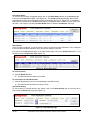
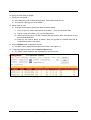
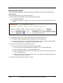
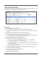
1
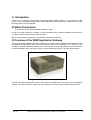
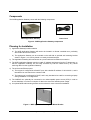
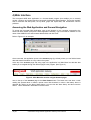
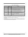
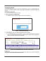
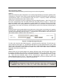
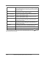
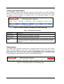
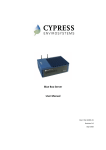
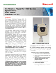
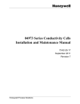
OneWireless Gauge Reader Application Gateway User's Manual 34-XY-25-33 Revision 2 July 2009 Notices and Trademarks Copyright 2009 by Honeywell International Inc. Revision 2 July 2009 While this information is presented in good faith and believed to be accurate, Honeywell disclaims the implied warranties of merchantability and fitness for a particular purpose and makes no express warranties except as may be stated in its written agreement with and for its customers. In no event is Honeywell liable to anyone for any indirect, special or consequential damages. The information and specifications in this document are subject to change without notice. Honeywell and OneWireless are registered trademarks of Honeywell International Inc. Other brand or product names are trademarks of their respective owners. Copyrights Copyright 2009 by Honeywell. All rights reserved. The information in this document is subject to change without notice. While reasonable precautions have been taken, Honeywell assumes no responsibility for any errors that may appear in this document. No part of this document may be copied or reproduced in any form or by any means without the prior written consent of Honeywell. Disclaimer HONEYWELL MAKES NO WARRANTY OF ANY KIND, EXPRESS OR IMPLIED, WITH REGARD TO THIS MATERIAL, INCLUDING, BUT NOT LIMITED TO, THE IMPLIED WARRANTIES OF MERCHANTABILITY AND FITNESS FOR A PARTICULAR PURPOSE. Honeywell reserves the right to make changes without further notice to the materials described herein. Honeywell does not assume any liability arising out of the application or use of any product described herein. Honeywell does not authorize its products for use in mission or safety critical systems or where a malfunction or failure may reasonably be expected to result in significant injury to the user, property damage or economic loss. The inclusion of Honeywell product in mission or safety critical system applications implies that the user assumes all risk of such use and in doing so indemnifies Honeywell and its supplier(s) against all charges. In no event is Honeywell liable to anyone for any indirect, special or consequential damages. Patents The products and technologies described in this document have patents pending. Honeywell Process Solutions 2500 West Union Hills Phoenix, AZ 85027 1-800 343-0228 ii OneWireless Gauge Reader Application Gateway User’s Manual July 09 Notices and Trademarks References About This Document This document describes Safety, Data collection, Web and OPC Interface for the OneWireless Gauge Reader Application Gateway (WGRAG). There is also a Trouble shooting section and Technical Specifications. Honeywell does not recommend using devices for critical control where there is a single point of failure or where single points of failure result in unsafe conditions. The OneWireless Gauge Reader is targeted at open loop control, supervisory control, and controls that do not have environmental or safety consequences. As with any process control solution, the end-user must weigh the risks and benefits to determine if the products used are the right match for the application based on security, safety, and performance. Additionally, it is up to the end-user to ensure that the control strategy sheds to a safe operating condition if any crucial segment of the control solution fails. Reference Information Document Name OneWireless Gauge Reader Application Gateway Manual Document ID Revision Number Publication Date 1 April 09 2 July 09 34-XY-25-33 References The following list identifies all documents that may be sources of reference for material discussed in this publication. Document Name Document Part Number OneWireless Gauge Reader Specification 34-XY-03-37 OneWireless Gauge Reader Installation Manual 34-XY-25-32 OneWireless Gauge Reader User Manual 34-XY-25-31 OneWireless Gauge Reader Model Selection Guide 34-XY-16-80 World Wide Web Honeywell Solution Support Online: http://www.honeywell.com/ps Elsewhere Call your nearest Honeywell office. Training Classes Honeywell Automation College: http://www.automationcollege.com July 09 OneWireless Gauge Reader Application Gateway User’s Manual iii Symbol Definitions The following table lists those symbols used in this document to denote certain conditions. Symbol Definition ATTENTION: Identifies information that requires special consideration. TIP: Identifies advice or hints for the user, often in terms of performing a task. CAUTION Indicates a situation which, if not avoided, may result in equipment or work (data) on the system being damaged or lost, or may result in the inability to properly operate the process. CAUTION: Indicates a potentially hazardous situation which, if not avoided, may result in minor or moderate injury. It may also be used to alert against unsafe practices. CAUTION symbol on the equipment refers the user to the product manual for additional information. The symbol appears next to required information in the manual. WARNING: Indicates a potentially hazardous situation, which, if not avoided, could result in serious injury or death. WARNING symbol on the equipment refers the user to the product manual for additional information. The symbol appears next to required information in the manual. WARNING, Risk of electrical shock: Potential shock hazard where HAZARDOUS LIVE voltages greater than 30 Vrms, 42.4 Vpeak, or 60 VDC may be accessible. ESD HAZARD: Danger of an electro-static discharge to which equipment may be sensitive. Observe precautions for handling electrostatic sensitive devices. Protective Earth (PE) terminal: Provided for connection of the protective earth (green or green/yellow) supply system conductor. Functional earth terminal: Used for non-safety purposes such as noise immunity improvement. NOTE: This connection shall be bonded to Protective Earth at the source of supply in accordance with national local electrical code requirements. Earth Ground: Functional earth connection. NOTE: This connection shall be bonded to Protective Earth at the source of supply in accordance with national and local electrical code requirements. Chassis Ground: Identifies a connection to the chassis or frame of the equipment shall be bonded to Protective Earth at the source of supply in accordance with national and local electrical code requirements. continued iv OneWireless Gauge Reader Application Gateway User’s Manual July 09 Symbol Description For radio equipment used in the European Union in accordance with the R&TTE Directive the CE Mark and the notified body (NB) identification number is used when the NB is involved in the conformity assessment procedure. The alert sign must be used when a restriction on use (output power limit by a country at certain frequencies) applies to the equipment and must follow the CE marking. July 09 OneWireless Gauge Reader Application Gateway User’s Manual v Table of Contents 1) INTRODUCTION .....................................................................................................I 2) SAFETY PRECAUTIONS .......................................................................................I 3) OVERVIEW OF THE WGR APPLICATION GATEWAY .........................................I Components............................................................................................................................................. 2 Planning for Installation ......................................................................................................................... 2 4) WEB INTERFACE.................................................................................................. 3 Accessing the Web Application and General Navigation ................................................................... 3 Checking Node Readings ....................................................................................................................... 4 Configuring Nodes .................................................................................................................................. 6 Checking the Node Status.................................................................................................................... 10 Using Alarms ......................................................................................................................................... 10 Working with Graphs ............................................................................................................................ 13 Using Historical Data Tables................................................................................................................ 16 5) DATA HISTORY................................................................................................... 18 6) OPC INTERFACE ................................................................................................ 19 7) TROUBLESHOOTING ......................................................................................... 20 8) TECHNICAL SPECIFICATIONS .......................................................................... 20 9) WARRANTY INFORMATION............................................................................... 20 10) SUPPORT SERVICES / CONTACT INFORMATION........................................... 22 vi OneWireless Gauge Reader Application Gateway User’s Manual July 09 1) Introduction Thank you for purchasing the Honeywell OneWireless Gauge Reader System. A core component of this system is our OneWireless Gauge Reader WGR Application Gateway (WGRAG). Please read this guide thoroughly before using the gateway. 2) Safety Precautions Do not expose the WGR Application Gateway to water. Do not try to repair yourself as it contains no user-serviceable parts. Contact a qualified service technician for repairs. See the Support section below for details. Make sure the gateway is installed in a temperature-controlled environment. 3) Overview of the WGR Application Gateway The Honeywell WGR Application Gateway (WGRAG), is a flexible industrial gateway that collects Honeywell OneWireless Gauge Reader data points and enables access to the readings from a variety of user interfaces. The WGR Application Gateway can be used as part of an overall existing systems infrastructure such as distributed control, supervisory control or asset management system or as a stand alone station. Figure 1 : WGR Application Gateway (WGRAG) Through the industry standard OPC Data Access protocol, the data can be connected to your existing plant systems. The data can also be viewed from any computer on the intranet using a standard web browser. July 09 OneWireless Gauge Reader Application Gateway User’s Manual 1 Components The WGR Application Gateway comes with the following components: WGR Application Gateway Power Cord Figure 2 : WGR Application Gateway components Planning for Installation 1) Application Gateway location selection a) The WGR Application Gateway will need to be located in a climate controlled room, preferably where other servers are housed. b) The Application Gateway can be mounted on the wall with an optional wall mounting bracket shown in Figure 3, or it can be placed on a sturdy horizontal surface. 2) The Application Gateway will need access to a power outlet and an Ethernet connection. 3) The WGR Application Gateway requires a static IP Address assignment from the IT department, so that the Application Gateway can be easily accessed by both the WGRs and by any clients retrieving data from the Application Gateway. 4) The unit has two Ethernet ports. a) The top port is configured as a Static IP port, with a default IP address of 192.168.254.1, and is intended to be connected to the customer LAN. b) The bottom port is configured for DHCP, and is only intended to be used for connecting a laptop during installation or for diagnostics. 5) The WGRAG can optionally be connected to an uninterruptable power source (UPS) in order to ensure that there is no loss or corruption of data in the event of a facilities power outage. 6) An optional WGR wall mounting bracket can be ordered for more convenient installation. Figure 3 : WGR Application Gateway Wall Mount Bracket 2 OneWireless Gauge Reader Application Gateway User’s Manual July 09 4) Web Interface The Honeywell WGR Web Application is a browser-based program that enables you to remotely monitor, configure, and review data from Honeywell OneWireless Gauge Readers. This section explains how to read and edit data points, set up alerts, graph and export data, and troubleshoot common problems. Accessing the Web Application and General Navigation To access the Honeywell Web Application, open a web browser on any computer connected to the same local area network (LAN) as the WGR Application Gateway. Type in the static IP address or host name of the WGRAG in the web browser address field, and click Enter. Refer to Figure 4 for an example. Figure 4 : Connect to the WGR Application Gateway Web Interface Once connected, the application opens to the READINGS page (by default), where you can find the latest data and status information on every node in the system. At the top of the READINGS page and every page in the application is a Main Menu bar with tabs that enable you to navigate through the different pages in the program. (See Figure 5.) Figure 5 : Main Menu bar used to navigate between pages Also on the top of the READINGS page is the Alarm Status button. The button turns red when a node reading has passed above or below a preset control limit threshold, or when a low battery alarm is detected. By clicking on the Alarm Status button, you can view the alarm history and also reset the alarms. This is described in detail later in the document. July 09 OneWireless Gauge Reader Application Gateway User’s Manual 3 Checking Node Readings The READINGS page enables you to check the summary of node readings. It also provides other detailed information, such as the time of the reading, as well as the upper and lower control limits and the status of a particular node. Figure 6 : Readings page shows summary of all nodes Get Node Readings To check the node readings, click on READINGS in the Main Menu bar. The Figure 6) with the following information: READINGS page appears (see ∗ Timestamp: Time when the last reading was taken. ∗ NodeID: Identification number that your Honeywell Field Representative originally assigns to a node for convenient reference. ∗ Description: A brief description of the node, for example, “Emergency Generator” or “Water Inlet Pressure.” ∗ Reading: Most recent reading taken from the node. Your Field Service Representative configures the update rate of each node when the system is installed. ∗ Units: Unit of measurement that applies to the reading. ∗ LCL: Lower control limit. ∗ UCL: Upper control limit. ∗ When a node reading falls below this value, the systems signals an alert. (See “Setting Up the Alarm.”) When a node reading rises above this value, the system signals an alert. (See “Setting Up the Alarm.”) Status: Indicates the general operating status of the node. Values are: OK, Inactive, Error, Lower Ctl Limit, Upper Ctl Limit, Low Battery Based on the status, individual rows are also highlighted to provide an extra visual cue. See Table 1 for a detailed description of each status and the highlighted color. 4 OneWireless Gauge Reader Application Gateway User’s Manual July 09 Table 1 : Status Column Details Status Highlight Color OK - Error Red Upper Ctr Limit (UCL) Orange If the reading exceeds the configured upper control limit. (Note: Each node has a separate control limit.) Lower Ctr. Limit (LCL) Orange If the reading drops below the configured lower control limit. (Note: Each node has a separate control limit.) Inactive Light Blue Low Battery Yellow Description The reading was received without error and is within limits. The WGR reported an error code. Consult with your installer to rectify any persistent error conditions. The node has stopped reporting data to the gateway for a period of time (4 * sample interval). The battery level has fallen below the low battery notification trip point. Tip: Similar to standard Web pages, the Honeywell Web Application pages are static (they don’t update automatically). To get updated values for any new readings, you must reload the page by pressing F5 on your keyboard or clicking the Refresh button on your web browser. Sort Readings You can temporarily sort a column of readings by ascending or descending value by simply clicking on any column heading that is underlined. The system does not save the sorting option selected, however, and reverts back to the default view when the page reloads. July 09 OneWireless Gauge Reader Application Gateway User’s Manual 5 Configuring Nodes You can add (commission), delete, and edit node configurations by going to the CONFIGURATION page. This page is password restricted, so that only the system administrator or authorized installer can access it. Access Node Configurations To access the WGR Node Configuration screen: 1) Click CONFIGURATION in the Main Menu. a) A dialog box (Figure 7) appears asking for a user name and password. Figure 7 : Administrator login page 2) In the dialog box, enter a user name and password, and click Log In. a) The CONFIGURATION page (Figure 8) appears. It has two clearly defined sections. A top section, where you can add and delete individual or multiple nodes. The bottom section displays all the nodes in the system that are visible to the gateway. Figure 8 : Main Configuration page to add, edit, or delete nodes Delete a Node To delete a node, enter the NodeID and click on the Delete button. Please note this action will delete the node and all of its associated historical data permanently. 6 OneWireless Gauge Reader Application Gateway User’s Manual July 09 Add (Commission) a Node There are three options for adding (commissioning) a new node to the gateway: Option 1) Nodes are configured by the Configuration Tool, and they begin attempting to contact the gateway when configuration is complete. These nodes are auto-detected and added to the Node list by the gateway as uncommissioned nodes. All uncommissioned nodes will have a temporary NodeID automatically assigned by the WGRAG with a value of 2000 or above. The user can commission the node by assigning a permanent NodeID between 1-1000. Click on the Edit link for the corresponding node in the table, which opens the dialog shown in Figure 11. Enter a new permanent NodeID value in the “Commission as new NodeID” box, and then click the Commission button. The Node is now officially added to the gateway and is fully commissioned. Please note, upon commissioning of the node, the temporary uncommissioned node and its temporary historical data is deleted. Option 2) Individual nodes can be manually added to the system prior to having them communicate to the gateway for the first time. Note that this requires manual entry of several additional pieces of data, which would otherwise be automatically entered in Option 1. The dialog box in the top section of the CONFIGURATION page enables adding or deleting nodes. (See Figure 9.) Figure 9 : Configuration page dialog box To add a node, enter the new NodeID (between 1-1000) and press the Add button. This will bring up a pop-up dialog box (See Figure 11). This dialog box will allow you to enter details about the node, so that when it does communicate to the gateway for the first time, it will automatically be fully commissioned without further intervention. Please refer to the details in the section “Edit a Node” below for additional information about each parameter field. Option 3) Multiple nodes can be manually added to the gateway efficiently using a text file method. Simply enter the properly formatted node information to the Nodeconfiguration.txt file on the gateway. This file is a tab-separated text file that lists all of the configuration parameters. An example file is shown in Figure 10. First click the Download button on the CONFIGURATION page in order to create the Nodeconfiguration.txt file on your PC. Then make your desired edits, and use the Upload button to load the new nodes and parameters from the edited configuration file. Figure 10 : Example Nodeconfiguration.txt (tab-separated) file July 09 OneWireless Gauge Reader Application Gateway User’s Manual 7 Figure 11 : Node Configuration pop-up dialog box Edit a Node To edit a node, go to the table in the lower half of the CONFIGURATION page. Click on the Edit link next to the node. This will launch a Node Configuration pop-up dialog box as shown in Figure 11. Table 2 describes the node configuration parameters. After editing the parameters, the Ok button must be clicked to save the newly edited fields. To cancel the edits, simply click on the Close button to close the dialog box without saving. Table 2 : Node Configuration Details 8 NodeID The NodeID of the Device, which is a short and convenient ID used to reference the node when creating graphs and tables. MAC Address Specifies the unique MAC Address of the node. This value must contain a valid MAC address for the system to function properly when the node is commissioned. Commission as new NodeID Used to assign a permanent NodeID to an uncommissioned node. The new NodeID needs to be set between 1-1000. Commission Button Click to commission a new Node. Name Basic text description of the node Unit Unit of measurement for the monitored gauge. Enter any short descriptive string, such as PSI, Deg C, kPa, etc. A binary type may also be specified for special situations (TRUE/FALSE, ON/OFF, or ACTIVE/INACTIVE). Node Math function Allows simple computations to be made on two physical node readings, by referencing their two NodeIDs. The resulting value is displayed as a virtual node, by creating a new NodeID for displaying the result of the math function. OneWireless Gauge Reader Application Gateway User’s Manual July 09 Decimal Precision Decimal Precision specifies the number of decimal places to display on the readings page for the node’s data. If no precision is specified, the number of decimal places will automatically be determined by the system for the node. Alarm Excursion # This is the number of consecutive times the node data limit must be exceeded before an Alarm condition is triggered. Alarm Threshold Min The lower control limit value. If the node reading drops below this number, an alarm condition is created. Alarm Threshold Max The upper control limit value. If the node reading rises above this number, an alarm condition is created. WGR Configuration Min This value is the minimum reading value on the gauge face. This value must be accurate for each gauge in order for the system to display the proper reading. WGR Configuration Max This value is the maximum reading value on the gauge face. This value must be accurate for each gauge in order for the system to display the proper reading. IP Address IP Address of the WGR device. This will automatically be updated by the WGRAG when it receives data packets from the node. OK Button Apply the changed settings to the node. Close Button Closes the dialog box To see the change log of the nodes that have been added/deleted/edited, click on the upper right portion of the web page. July 09 OneWireless Gauge Reader Application Gateway User’s Manual icon in the 9 Checking the Node Status The OneWireless Gauge Reader periodically transmits its health status to the WGR Application Gateway. The health status can be viewed by loading the STATUS page. This read-only screen (Figure 12) displays the status conditions of configured nodes on the Application Gateway. The status descriptions are shown in Table 3. Figure 12 : Health information is displayed in the Node Status page Table 3 : Node Status Descriptions Parameter Description Battery Status The battery level as a percentage of full-charge. Temperature The internal temperature (Celsius) of the WGR RSSI The Received Signal Strength Indicator (RSSI). This is an indicator of wireless signal strength based on messages received by the WGR from its associated Multinode. Using Alarms The Honeywell Web Application provides alerts for potential problems as they arise in the monitored nodes. The system triggers an alarm when a node reading exceeds an upper control limit or drops below a lower control limit. When an alarm is triggered, the Alarm Status button on the READINGS page turns red (Figure 13). Each alarm event is stored in the ALARM HISTORY log, and a summary of nodes that have triggered an alarm condition are shown on the ALARM STATUS page. Figure 13 : Alarm Status button on the Readings page 10 OneWireless Gauge Reader Application Gateway User’s Manual July 09 View Alarm Status To view the current status of triggered alarms, click on the Alarm Status button on the READINGS page to bring up the ALARM STATUS page. (See Figure 14.) The ALARM STATUS page displays which nodes had triggered an alarm, and what was the reason for the alarm (above UCL, below LCL, or low battery). Nodes can be cleared from the ALARM STATUS page by resetting the alarm condition for each node or for all nodes. This is done by clicking the Alarm Reset button, to load the ALARM RESET web page. Figure 14 : Alarm Status page Reset Alarms Once an alarm is triggered, it must be reset in order to receive new alarm indications. This is designed to avoid continuous alarm indications every time a new reading is received. From either the ALARM HISTORY page, or the alarm status page, click on the Alarm Reset button. This will take you to the ALARM RESET page (Figure 15). Figure 15 : Alarm Reset page To reset all alarms: 1) Click the Reset All button. a) This will reset the alert status for all nodes. To reset alarms for individual nodes: 1) Click the Reset button in the row corresponding to the desired node a) This will reset the alert status for only this node. View Alarm History To view a history of all past alarms in the system, click on the Alarm History item in the menu bar to bring up the ALARM HISTORY page (See Figure 16). Figure 16 : Alarm History page July 09 OneWireless Gauge Reader Application Gateway User’s Manual 11 To specify an alarm history to display: 1) Specify the time period. a) In the dialog box, enter a value for Start Date & Time and End Date & Time. b) The format is m/dd/yyyy hh:mm:ss AM/PM 2) Select nodes to view. a) There are several ways to specify the desired nodes to display. i) You may type in a comma separated list of NodeIDs (“1,2,3”) into the NodeID field ii) Type in a range of NodeIDs (“1-3”) into the NodeID field iii) Use the pull-down menu in the List Of Nodes field, and click the down-arrow button to copy them to the NodeID field iv) Check the box next to Select All Nodes, which will populate the NodeID field with all commissioned nodes in the system. 3) Click the Update button to display the results. a) The alarm history displays at the bottom of the screen. (See Figure 17) 4) To optionally export the data, click the Export to Excel button. a) The system creates a data file and downloads it in an Excel format. Figure 17 : The Alarm History page shows all past alarms for a specified period you 12 OneWireless Gauge Reader Application Gateway User’s Manual July 09 Working with Graphs The Honeywell Web Application provides basic graphing capability for the stored node readings data. Create a Graph To generate a graph from one or more node readings: 1) Click on Graph in the Main Menu bar to load the GRAPH web page. a) The GRAPH page appears. b) It includes two sections: a dialog box at the top (see Figure 18) and a graph portion at the bottom. Figure 18 : Graph Dialog Controls 1) In the graph dialog box, enter values for Start Date & Time and End Date & Time. a) The format includes both date and time as m/dd/yyyy hh:mm:ss AM or PM. b) You may also click on one of the numbered buttons next to “Days” in order to quickly specify a common time range from 1-30 days prior to the End Data & Time. 2) Specify the NodeIDs to graph in the NodeID text field. a) There are several ways to specify the desired nodes to display. i) You may type in a comma separated list of NodeIDs (“1,2,3”) into the NodeID field ii) Type in a range of NodeIDs (“1-3”) into the NodeID field iii) Use the pull-down menu in the List Of Nodes field, and click the down-arrow button to copy them to the NodeID field iv) Check the box next to Select All Nodes, which will populate the NodeID field with all commissioned nodes in the system. 3) Select from the additional options shown in Table 4. July 09 OneWireless Gauge Reader Application Gateway User’s Manual 13 Table 4 : Additional graphing options Auto Scale The graph will automatically scale the vertical axis based on the data values. By default, this option is selected. To turn off auto scale, uncheck the checkbox, and then the “Min” and “Max” fields will be enabled for manual entry. Min If Auto Scale is turned off, specify the min Y value on the graph. Max If Auto Scale is turned off, specify the max Y value on the graph. Y-Axis Zoom Allows the mouse cursor to zoom both X and Y axis, instead of only the X axis. By default zooming occurs only on the X axis Tooltip This enables the display of each actual reading value on the graph by hovering the mouse pointer over a point on the graph. By default this option is turned off to speed up graphing time, particularly for large data sets. Log When enabled, changes the Y-axis to a logarithmic scale instead of a default linear scale. Legend Allows the graphing legend to be disabled in order to make more room for the graph on the web page. Reset Zoom Resets the graph back to the default view (no zoom) 4) Click Show Graph to display the graph. a) An X-Y graph appears at the bottom of the page for the requested data range. (See Figure 19.) Tip: If you click Clear Graph, all data in the dialog box clears, except for the NodeID list. If you want to remove a single node from the graph, you must look up the NodeID and then go into the list and delete it manually. Figure 19 : A sample graph showing captured data 14 OneWireless Gauge Reader Application Gateway User’s Manual July 09 Graph Legend When graphing multiple nodes, the graph legend will have the nodes listed in order from the highest reading value to lowest readings value based on the last displayed value of each series. This allows easier identification of each data series when graphing many nodes. To improve graphing performance, very large sets of data will have some data compression. To ensure all desired points are graphed, adjust the Start Date and End Date to manually zoom into any area of interest for maximum detail. Identify a Point Tooltips can be used to conveniently determine the exact timestamp and data value for any point on the graph. 1) Enable Tooltips at the top of the page, which will cause the page to re-load with all of the additional required information. 2) Hover the mouse cursor over a point on the graph, and a small pop-up box will appear showing the corresponding NodeID, timestamp, and reading value. Zoom To zoom-in to a region of the graph, point the mouse cursor to the starting location on the graph, and then hold down the left button and drag to the right to define the zoom region, then release the button. You will be able to scroll the graph left and right to see the entire data set from the originally specified date range. By default, zooming occurs in the X axis only. To zoom in on both the X and Y axis, first enable the “YAxis Zoom” option. When dragging the mouse cursor to define the zoom region, start with the upper left corner, and drag to the lower right corner of the desired zoom area. July 09 OneWireless Gauge Reader Application Gateway User’s Manual 15 Using Historical Data Tables The Honeywell Web Application provides the ability to display historical data in table format. historical data may also be exported and downloaded in Excel format. The Figure 20 : Table page allows you to list the data and export to Excel Create a Table To generate a table from several node readings: 1) Click on Table History in the Main Menu bar to load the TABLE HISTORY web page. a) It is very similar to the bottom. GRAPH page, with a dialog box on the top and data displayed at the 2) In the dialog box, enter values for Start Date & Time and End Date & Time. a) The format includes both date and time as m/dd/yyyy hh:mm:ss AM or PM. b) You may also click on one of the numbered buttons next to “Days” in order to quickly specify a common time range from 1-30 days prior to the End Data & Time. 3) Specify the NodeIDs to display in the NodeID text field. a) There are several ways to specify the desired nodes to display. i) You may type in a comma separated list of NodeIDs (“1,2,3”) into the NodeID field ii) Type in a range of NodeIDs (“1-3”) into the NodeID field iii) Use the pull-down menu in the List Of Nodes field, and click the down-arrow button to copy them to the NodeID field iv) Check the box next to Select All Nodes, which will populate the NodeID field with all commissioned nodes in the system. 4) A table appears at the bottom on the screen displaying the following historical data parameters a) Timestamp: Timestamp of data reading b) Node ID: The unique ID number of the WGR node c) Description: The name of the node d) Reading: The value read by the WGR 16 OneWireless Gauge Reader Application Gateway User’s Manual July 09 e) Units: The units of the gauge (e.g. PSI) f) Above UCL: Indicates if an over-limit alarm occurred g) Below LCL: Indicates if a below-limit alarm occurred h) LCL: The lower control limit (LCL) value i) UCL: The upper control limit (UCL) value 5) To optionally export the data table, click the Export to Excel button. a) The system creates an Excel file and downloads it onto your computer. July 09 OneWireless Gauge Reader Application Gateway User’s Manual 17 5) Data History The OneWireless Gauge Reader Application Gateway stores data from gauge readers for a period of 12 months. After 12 months, data is cleaned from the application gateway's database on a first in, first out priority. Historical data is periodically stored in the WGRAG in the “c:\wgrlog” folder every week. Users can manually restore this archived historical data to a MSSQL database, if desired. Alternatively, data can be preserved by exporting to an Excel file from the Web application. When OPC Server is used and the gauge reader data is regularly accessed by other client systems such as Experion or Field Device Manager, data retention is determined by the policies set for these individual client applications. 18 OneWireless Gauge Reader Application Gateway User’s Manual July 09 6) OPC Interface To interface to existing plant infrastructure, the WGR Application Gateway contains an OPC Data Access server. Please consult with your Honeywell support representative for interfacing to the WGRAG using OPC. The name of the OPC server on the WGRAG is “ WGR.OPC.1” The following OPC tags are available: ∗ WGRNodeID: The configured WGR NodeID ∗ WGRReading: WGR device reading ∗ WGRUnit: WGR reading unit type (E.g. PSI, C, F) ∗ WGRBatteryStatus: WGR battery status reading (%) ∗ WGRTemperature: WGR internal temperature reading (C) ∗ WGRRSSI: Received Signal Strength Indicator ∗ WGRTimestamp: Timestamp when the data arrived ∗ WGRIPAddress: WGR IP address ∗ WGRMACAddress: WGR device MAC address ∗ WGRFriendlyName: WGR device friendly name July 09 OneWireless Gauge Reader Application Gateway User’s Manual 19 7) Troubleshooting The most common problems with the WGR Application Gateway are listed below: The web page displays an error message. This happens sometimes when the cached version of the web page on a local PC is not compatible with the latest version on the Application Gateway. Try pressing CTL+F5 several times, which should force the web browser on your local PC to refresh the web page from the Application Gateway. I’m not able to create a graph. When I click, “Show Graph,” nothing happens. Generally, this means no data was available. Check your start and end time to make sure that it includes data. The graph takes a long time to load This typically means that a large amount of data was specified. Try reducing the date range, or number of nodes, or disable Tooltips in order to reduce the amount of data to load and render. The readings on the gateway do not match the readings on the device. The readings are based on a percentage of full scale determined from the “MinValue” and “MaxValue” parameters entered in the CONFIGURATION page. If the “MinValue” and “MaxValue” are not configured correctly on both the WGR and WGR Application Gateway, then the “Reading” value may be incorrect. If you have additional problems, please contact us. information. See the Support section below for contact 8) Technical Specifications User Interface: Available Data Protocols: Approvals: Power Supply Operating Temperature: Storage Temperature: Humidity: Enclosure: Dimensions: Weight: Built in Web Server for easy browser access to data and trending OPC Data Access Server CE and RoHS Compliant 90-240 VAC 0°C to 45°C -20°C to +80°C 10-90%, non-condensing Ruggedized aluminum industrial chassis 12.0 in x 8.3 in x 4.1 in (300 mm x 210 mm x 104.5 mm) 14 lbs (6.3 kg) 9) Warranty Information Every product comes with a full one-year parts and labor warranty. 20 OneWireless Gauge Reader Application Gateway User’s Manual July 09 This page has been intentionally left blank July 09 OneWireless Gauge Reader Application Gateway User’s Manual 21 10) Support Services / Contact Information For application assistance, current specifications, pricing, or name of the nearest Authorized Distributor, contact one of the offices below. ASIA PACIFIC Control Products Asia Pacific Headquarters Phone: +(65) 6355-2828 Fax: +(65) 6445-3033 Asia Pacific Global Technical Support Field Instruments Phone: +65 6580 3156 Fax: +65 6445-3033 Process Instruments Phone: (603) 76950 4777 Fax: (603) 7958 8922 Australia Honeywell Limited Phone: +(61) 7-3846 1255 FAX: +(61) 7-3840 6481 Toll Free 1300-36-39-36 Toll Free Fax: 1300-36-04-70 China – PRC - Beijing Honeywell China Inc. Phone: +(86-10) 8458-3280 Fax: +(86-10) 8458-4650 China – PRC - Shanghai Honeywell China Inc. Phone: (86-21) 5257-4568 Fax: (86-21) 6237-2826 China – PRC - Chengdu Honeywell China Inc. Phone: +(86-28) 8678-6348 Fax: +(86-28) 8678-7061 China – PRC - Xi’an Honeywell China Ltd - Xi’an. Phone: +(86-29) 8833-7490 Fax: +(86-29) 8833-7489 China – PRC - ShenzhenHoneywell China Inc. Phone: +(86) 755-2518-1226 Fax: +(86) 755-2518-1221 Indonesia PT Honeywell Indonesia Phone: +(62) 21-535-8833 FAX: +(62) 21-5367 1008 India Automation India Ltd. Honeywell Ltd. Phone:+(91) 5603-9400 Fax: +(91) 5603-9600 Japan Honeywell Inc. Phone: +(81) 3 6730 7150 Fax: +(81) 3 6730 7228 Malaysia Honeywell Engineering Sdn Bhd Phone: +(60-3) 7950-4776 Fax: +(60-3) 7958-8922 New Zealand Honeywell Limited Phone: +(64-9) 623-5052 Fax: +(64-9) 623-5060 Toll Free (0800) 202-088 Philippines Honeywell Systems (Philippines) Inc. Phone: +(63-2) 633-283031/ 636 1661-62 Fax: +(63-2) 638-4013 Singapore Honeywell Pte Ltd. Phone: +(65) 6580 3278 Fax: +(65) 6445-3033 South Korea Honeywell Korea Co Ltd Phone: +(822) 799 6315 Fax: +(822) 792 9015 Thailand Honeywell Systems (Thailand) Ltd. Phone: +(662) 693-3099 FAX: +(662) 693-3089 Taiwan R.O.C. Honeywell Taiwan Ltd. Phone: +(886-2) 22451000 FAX: +(886-2) 2245-3241 SE Asia Countries see Honeywell Pte Ltd (Singapore) for: Pakistan, Cambodia, Guam, Laos, Myanmar, Vietnam, East Timor SE Asia Countries see Honeywell Automation India Ltd for: Bangladesh Nepal Sri Lanka EUROPE Austria Honeywell Austria GmbH Phone: +43 (316)400123 FAX: +43 (316)40017 Belgium Honeywell SA/NV Phone: +32 (0) 2 728 24 07 FAX: +32 (0) 2 728 22 45 Bulgaria Honeywell EOOD Phone: +(359) 2 40 20 900 FAX: +(359) 2 40 20 990 Honeywell Process Solutions Honeywell 2500 W. Union Hill Drive Phoenix, Arizona 85027 Czech Republic Honeywell spol. s.r.o. Phone: +420 242 442 232 FAX: +420 242 442 131 Slovak Republic Honeywell s.r.o. Phone: +421-2-58247 410 FAX: +421-2-58247 415 Denmark Honeywell A/S Phone: +(45) 39 55 55 55 FAX: +(45) 39 55 55 58 Spain Honeywell S.A. Phone: +34 (0)91313 61 00 FAX: +34 (0)91313 61 30 Finland Honeywell OY Phone: +358 (0)20752 2753 FAX: +358 (0) 20752 2751 Sweden Honeywell AB Phone: +(46) 8 775 55 00 FAX: +(46) 8 775 56 00 France Honeywell SA Phone: +33 (0)1 60198075 FAX: +33 (0)1 60198201 Germany Honeywell AG Phone: +49 (69)8064-299 FAX: +49 (69)806497336 Hungary Honeywell Kft. Phone: +36-1-451 4300 FAX: +36-1-451 4343 Italy Honeywell S.p.A. Phone:+390292146307 FAX: +39 0292146377 The Netherlands Honeywell B.V. Phone: +31 (0) 20 5656200 FAX: +31 (0) 20 5656210 Norway Honeywell A/S Phone: (45) 39 55 55 55 Poland Honeywell Sp. zo.o Phone: +48-22-6060900 FAX: +48-22-6060901 Portugal Honeywell Portugal Lda Phone: +351 21 424 5000 FAX: +351 21 424 50 99 Romania Honeywell Bucharest Phone: +40 (0) 21 2316437 FAX: +40 (0) 21 2316439 Russian Federation (RF), ZAO "Honeywell" Phone: +7 (095) 796 98 00 FAX: +7 (495) 797 99 64 Switzerland Honeywell AG Phone: +41 18552448 FAX: +(41) 1 855 24 45 Turkey Honeywell Turkey A.S. Phone: +90 216 578 71 00 FAX: +90 216 575 66 35 Ukraine Honeywell Tel: +380-44-201 44 74 Fax: +380-44-201-44-75 United Kingdom Honeywell Control Systems Ltd. Phone: +44 (0)1344 655251 FAX: +44 (0) 1344 655554 MIDDLE EAST Abu Dhabi U A E Middle East Headquarters Honeywell Middle East Ltd. Phone: +971 2 4041246 FAX: +971 2 4432536 Sultanate of Oman Honeywell & Co Oman LLC Phone: +968 24 701153/ Ext.33 FAX +968 24 787351 AFRICA Mediterranean & African Distributors Honeywell SpA Phone: +39 (02) 250 10 604 FAX: +39 (02) 250 10 659 South Africa (Republic of) and sub saharan Honeywell Southern Africa Honeywell S.A. Pty. Ltd. Phone: +27 11 6958000 FAX +27 118051504 NORTH AMERICA Canada Honeywell LTD Phone: 1-800-737-3360 FAX: 1-800-565-4130 USA Honeywell Process Solutions, Phone: 1-800-343-0228 FAX: 1-717-771-8251 Email:sc-cp-appssales@ honeywell.com LATIN AMERICA Argentina Honeywell S.A.I.C. Phone: +(54-11) 4383-3637 FAX: +(54-11) 4325-6470 Brazil Honeywell do Brasil & Cia Phone: +(55-11) 7266-1900 FAX: +(55-11) 7266-1905 Chile Honeywell Chile, S.A. Phone: +(56-2) 233-0688 FAX: +(56-2) 231-6679 Mexico Honeywell S.A. de C.V. Phone: +(52) 55 5259-1966 FAX: +(52) 55 5570-2985 Saudia Arabia Honeywell Turki Arabia Ltd Jubail Office Phone: +966-3-341-0140 Fax: +966-3-341-0216 Honeywell - ATCO Dammam Office Phone: 0096638304584 Fax: 0096638338059 Puerto Rico Honeywell Inc. Phone: +(809) 792-7075 FAX: +(809) 792-0053 Kuwait Honeywell Kuwait KSC Phone:+965 242 1327 to 30 Fax: +965 242 8315 And Phone: +965 326 2934/1821 Fax: +965 326 1714 Venezuela Honeywell CA Phone: +(58-2) 238-0211 FAX: +(58-2) 238-3391 34-XY-25-33 Rev.2 July 2009 ©2009 Honeywell International Inc. Trinidad Honeywell Inc. Phone: +(868) 624-3964 FAX: +(868) 624-3969