1
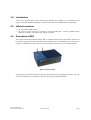
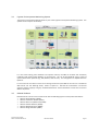
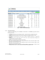
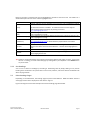
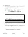
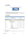
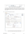
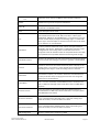
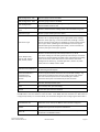
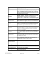
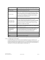
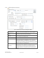
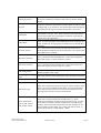
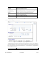
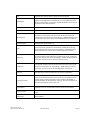
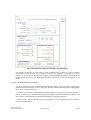
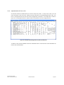
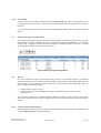
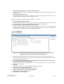
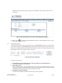
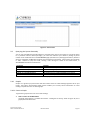
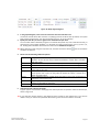
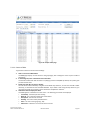
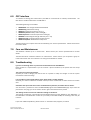
Blue Box Server
User Manual
Doc # 152-10201-01
Revision 2.0
Sept 2010
Copyrights
Copyright 2008 by Cypress Envirosystems. All rights reserved.
The information in this document is subject to change without notice. While reasonable precautions have been
taken, Cypress Envirosystems assumes no responsibility for any errors that may appear in this document. No part
of this document may be copied or reproduced in any form or by any means without the prior written consent of
Cypress Envirosystems.
Disclaimer
CYPRESS ENVIROSYSTEMS MAKES NO WARRANTY OF ANY KIND, EXPRESS OR IMPLIED, WITH REGARD TO THIS
MATERIAL, INCLUDING, BUT NOT LIMITED TO, THE IMPLIED WARRANTIES OF MERCHANTABILITY AND FITNESS FOR
A PARTICULAR PURPOSE. Cypress Envirosystems reserves the right to make changes without further notice to the
materials described herein. Cypress Envirosystems does not assume any liability arising out of the application or
use of any product or information described herein. Cypress Envirosystems does not authorize its products for use
in mission or safety critical systems or where a malfunction or failure may reasonably be expected to result in
significant injury to the user. The inclusion of Cypress Envirosystems’ product in mission or safety critical system
applications implies that the manufacturer assumes all risk of such use and in doing so indemnifies Cypress
Envirosystems against all charges. In no event is Cypress Envirosystems liable to anyone for any indirect, special or
consequential damages.
Table of Contents
1.0
2.0
3.0
4.0
5.0
6.0
7.0
8.0
9.0
10.0
11.0
Introduction ........................................................................................................................ 4
Safety Precautions .............................................................................................................. 4
Description of BBS............................................................................................................... 4
3.1 Cypress Envirosystems Monitoring System.............................................................. 5
3.2 Related Products....................................................................................................... 5
Setup Instructions ............................................................................................................... 6
4.1 Components.............................................................................................................. 6
Web Console ....................................................................................................................... 7
5.1 Starting the Program and General Navigation ......................................................... 7
5.2 Readings Page ........................................................................................................... 7
5.3 Other Readings Pages ............................................................................................... 9
5.4 Configuring Nodes................................................................................................... 11
5.5 Battery and Signal Strength Status ......................................................................... 27
5.6 Alarms ..................................................................................................................... 27
5.7 View Alarm History ................................................................................................. 29
5.8 Site Settings............................................................................................................. 31
5.9 Querying the System Remotely .............................................................................. 32
5.10 Graphs ..................................................................................................................... 32
5.11 Using Tables to Export Data.................................................................................... 34
5.12 Reports.................................................................................................................... 36
OPC Interface .................................................................................................................... 37
Care and Maintenance...................................................................................................... 37
Troubleshooting................................................................................................................ 37
Technical Specifications .................................................................................................... 38
Support.............................................................................................................................. 38
Warranty Information....................................................................................................... 38
Cypress Envirosystems
Doc # 152-10201-01 Rev 2.0
BBS User Manual
Page 3
1.0 Introduction
Thank you for purchasing the Cypress Envirosystems Blue Box Server (BBS), a core component of the
Cypress Envirosystems Monitoring System. Please read this manual thoroughly before using the BBS.
2.0 Safety Precautions
•
•
Do not expose the BBS to water.
Do not try to repair yourself as it contains no user-serviceable parts. Contact a qualified service
technician for repairs. See Section 10.0, Support, for details.
3.0 Description of BBS
The Cypress Envirosystems Blue Box Server, BBS, is a flexible industrial server that collects wireless data
from various Cypress Envirosystems field devices and enables access to the readings from a variety of user
interfaces. The BBS can be used as part of an overall existing infrastructure or as a stand alone station.
Figure 1. Blue Box Server
Through industry standard protocols, the data can be connected to your existing plant systems. The data
can also be viewed from any computer on the intranet using a standard web browser.
Cypress Envirosystems
Doc # 152-10201-01 Rev 2.0
BBS User Manual
Page 4
3.1
Cypress Envirosystems Monitoring System
The Cypress Envirosystems Blue Box Server is part of the Cypress Envirosystems Monitoring System. This
system can be setup one of two ways:
Figure 2. Cypress Envirosystems Monitoring System Setup Options
For users with existing plant databases and operator stations, the BBS can forward data seamlessly
integrating with existing plant SCADA or IT infrastructure. This can be accomplished using a variety of
open communication protocols (e.g. OPC, BACnet, web services). This configuration is depicted above as
Option A.
For users who do not need to connect to an existing infrastructure, the BBS can also serve as a standalone
Web Server and Text Message Server, shown as Option B. Standard PC workstations can become
operator stations simply by using any standard web browser. Alarm notifications can be sent via email or
SMS to cell phones.
3.2
Related Products
Blue Box Servers can be used to communicate with the following Cypress Envirosystems field devices:
• Wireless Gauge Readers (WGRs)
• Wireless Transducer Readers (WTRs)
• Wireless Steam Trap Monitors (WSTMs)
• Wireless Freezer Monitors (WFMs)
• Wireless Battery Monitors (WBMs)
• Wireless Range Extenders (WREs)
Cypress Envirosystems
Doc # 152-10201-01 Rev 2.0
BBS User Manual
Page 5
4.0 Setup Instructions
4.1
Components
The BBS comes with the following components:
BBS
Antennas
Power Cord
Connect the antennas to the back of the BBS as shown below. Then connect the power cord. To turn on
the BBS press the rocker switch highlighted below.
Power switch
Figure 3. BBS Power Switch Location
To change the receiver channel frequency, set the DIP switches accordingly.
Frequency
Dip Switches
-Channel Set A (2,74)
-Channel Set B (6,78)
-Channel Set C (24,50)
-Channel Set D (30,54)
Figure 4. BBS Channel Frequency Configuration
Cypress Envirosystems
Doc # 152-10201-01 Rev 2.0
BBS User Manual
Page 6
5.0 Web Console
The Cypress Envirosystems Web Console is a browser-based program that enables you to remotely
monitor, configure, and review data from wireless field devices. This section explains how to read and edit
data points, set up alerts and notifications, graph and export data, and troubleshoot common problems.
5.1
Starting the Program and General Navigation
To start the Cypress Envirosystems Web Console, open a Web browser and type in the IP address or name
of the Blue Box Server and click Enter.
Figure 5. Cypress Envirosystems Web Console Main Menu Bar
Once the web page loads, the application opens to the READINGS page (by default), where you can find
information on every data point, or node, in the system.
At the top of the READINGS page and every page in the application is a Main Menu bar with tabs that
enable you to navigate through the different pages in the program. The BBS may be set up to receive
data from multiple types of field devices. If so, there the various field devices will have their own pages.
See Figure 6 below.
Figure 6. Cypress Envirosystems Web Console Main Menu Bar
5.2
Readings Page
The READINGS page enables you to check the summary of node readings. It also provides other detailed
information, such as the time of the reading, as well as the upper and lower control limits and the status
of a particular node. Figure 7 below shows a sample WGR AND WTR READINGS page.
Cypress Envirosystems
Doc # 152-10201-01 Rev 2.0
BBS User Manual
Page 7
Figure 7. WGR and WTR READINGS page
5.2.1 Get Node Readings
To check your node readings, click on READINGS in the Main Menu. The READINGS page appears with the
following information:
•
•
•
•
•
•
•
•
Timestamp: Time when the last reading was taken. This time is based on the BBS system clock.
NodeID: Identification number that your service representative originally assigns to a node.
Description: A brief description of the node, for example, “Emergency Generator” or “Water Inlet
Pressure.”
Reading: Most recent reading taken from the node. Your service representative configures the
update rate when the system is installed.
Units: Unit of measurement that applies to the reading.
LCL: Lower control limit. When a node reading falls below this value, the systems signals an alert.
(See Section 5.6, Setting Up the Alarm)
UCL: Upper control limit. When a node reading rises above this value, the system signals an alert.
(See Section 5.6, Setting Up the Alarm)
Status: Indicates the status of the node, for example, whether it is okay, inactive, or below or above
acceptable limits. Values are: OK, Inactive, Error, Lower Ctl Limit, Upper Ctl Limit.
Cypress Envirosystems
Doc # 152-10201-01 Rev 2.0
BBS User Manual
Page 8
Based on the status, individual rows are also highlighted to provide an extra visual cue. See Table 1 for a
detailed description of each status and the highlighted color.
Error
Reported by WGR. Row is highlighted in red
If Node readings have not changed in past 2 days the row is highlighted in yellow.
Verify
By default this feature is disabled. To enable this feature contact Cypress
Envirosystems field service group by sending an email to
[email protected]
If the reading for the UCL limit exceeds the limit for the node set by the user, the
row is highlighted in orange
If the reading for the UCL drops below the limit for the node set by the user, the
row is highlighted in orange
This status will show if a batteries are low. Please contact
[email protected] to schedule battery replacements. Row will be
highlighted in Yellow.
This status is displayed if a Field Device has been configured on the BBS, but no
data has ever been sent from that field device. The Row will be highlighted in
gray.
This is the default status of the Node. The row is not highlighted
This status is displayed if a field device has stopped sending data to the BBS. Row
will be highlighted in blue.
Upper Ctr Limit
(UCL)
Lower Ctr Limit (LCL)
Low Battery
No Data
OK
Inactive
Table 1. Status Column Details
Tip: Similar to standard web pages, the Cypress Envirosystems Web Console pages are static. To get a new
value on a reading, you must reload the page by clicking F5 on your keyboard or the Reload button
on your browser.
5.2.2 Sort Readings
You can sort a column of readings by ascending or descending value by simply clicking on any column
heading that is underlined. The system does not save sorts, however, and reverts back to the default view
when the page reloads.
5.3
Other Readings Pages
Depending on the field device, the readings page may look a little different. WGRs and WTRs share the
same page and the data is displayed as seen above in Figure 7.
Figure 8 and Figure 9 show other examples of what the readings page will look like.
Cypress Envirosystems
Doc # 152-10201-01 Rev 2.0
BBS User Manual
Page 9
Figure 8. The Wireless Steam Trap Monitor (WSTM) Readings Page
Figure 9. Wireless Freezer Monitor (WFM) Readings Page
Figure 10. Wireless Battery Monitor (WBM) Readings Page
Cypress Envirosystems
Doc # 152-10201-01 Rev 2.0
BBS User Manual
Page 10
5.3.1 WSTM Readings Page
Users can specify which WSTM columns they would like to see in READINGS page by selecting columns from
the SITE SETTINGS WSTM Tab. The column selections will be saved as a browser cookie to the local computer
so users from different computers may select different columns to view.
Figure 11. Available WSTM fields (found in the Site Settings page)
In addition to the status fields detailed in Table 1 above, WSTMs will report the following in the condition
column based on the alarm profile set in the CONFIGURATION page.
Blowing
The trap is blowing steam. The row is highlighted in red.
Leaking
The trap is starting to blow steam. The row is highlighted in orange.
Flooded
The trap is building up condensate on the inlet. The row is highlighted in red.
Out of Service
There is no steam going to the trap. It is not being used in the system. The row is
highlighted in blue.
Offline
The WSTM is not reporting data to the BBS. The row is highlighted in yellow.
No Data
The WSTM has never reported any data to the BBS. The row is highlighted in yellow.
Good
This is the default status of the Node. The row is not highlighted.
Table 2. WSTM Condition Field
5.4
Configuring Nodes
You can add, delete, and edit node configurations by going to the CONFIGURATION page. This page is
password restricted, so that only the system administrator can access it. If multiple devices have been
setup to communicate with the BBS, each device will have a separate configuration page
5.4.1 Access Node Configurations
To access the Node Configuration screen:
1.
Click CONFIGURATION in the Main Menu.
A dialog box, shown in Figure 12, appears asking for a user name and password.
Cypress Envirosystems
Doc # 152-10201-01 Rev 2.0
BBS User Manual
Page 11
Figure 12. Administrator login page
2.
In the dialog box, enter a user name and password, and click Log In.
The configuration page appears, as shown in Figure 13 below. It has two clearly defined sections: a
top section, where you can add and delete individual or multiple nodes, and a bottom section that
displays all the nodes in the system that are visible to the server.
Figure 13. Main Configuration page
5.4.2 Add or Delete a Node
The dialog box in the top section of the CONFIGURATION page enables you to add or delete nodes, as shown
in Figure 14 below.
Cypress Envirosystems
Doc # 152-10201-01 Rev 2.0
BBS User Manual
Page 12
Figure 14. The upper dialog box in the CONFIGURATION page
Every field device is associated with a NodeID. Field devices are configured by the handheld device and
start transmitting data, but the BBS must be configured to collect data for that device. To add a node,
enter the new Node ID and press the Add button. This will bring up a pop-up dialog box. See Figure 15
below. This dialog box will allow you to edit the node settings. Please see below in the section “Edit a
Node” for details.
5.4.2.1
WGR and WTR Configuration Parameters
Figure 15. Node Configuration pop-up dialog box for WGRs and WTRs
Cypress Envirosystems
Doc # 152-10201-01 Rev 2.0
BBS User Manual
Page 13
Available
List
Node
Nodes that can be seen by the BBS but have not been configured.
NodeID
NodeID of the Cypress Envirosystems field device
Device ID
A unique identifier for a WTR device. If the user does not input a value,
the default is the NodeID number.
Name
A basic description of the node.
Unit
Unit of measurement for each Gauge. The user will either specify the
type of measurement such as PSI, H2O, Inch, LBS, or a binary type
(TRUE/FALSE, ON/OFF or ACTIVE/INACTIVE). In case of Binary unit type
the Unit column display is empty in the Readings page. For WTRs with
Device Type = Thermocouples or Thermistors the this field can be either
“C” for Celsius or “F” for Fahrenheit
Node Detail
If a binary value was used in the “Unit” column, the type of binary is
displayed in this column. Additionally, in applications requiring a delta
reading between two existing nodes a virtual delta node can be
configured. Values for the delta nodes are computed based on the delta
logic specified and are updated whenever the existing nodes change.
Node Math function
Select this for the Steam Trap node. Enter Node1 and Node2 that will be
used to calculate the reading for new node. E.g. Node3 = Node1-Node2
Precision
Precision is used to set the number of decimal places to display on the
readings page. If no precision is used, decimal places will be displayed
depending on how large or small the reading value is at the time.
Update Rate
Enable Alarm
Update rate as it has been configured on the field device (duration of
time between samples). This is used to determine if the field device is
inactive (no wireless data). Changing this value does not change the
update rate on the field device.
This field must be checked for the SMS alarm to be activated for the
node. If a limit is exceeded, and the SMS Alarm box is checked for the
node, an SMS Text message and/or email will be sent to all SMS Alarm
recipients.
Alarm Excursion #
This is the number of consecutive times the node data limit has is
exceeded before an SMS and/or Email notification is sent. (Only works
when SMS Alarm is checked)
Min Alarm Threshold
This is a specified lowest allowable value. If the node reading drops
below this number, an alarm condition is created.
Max Alarm Threshold
This is a specified highest allowable value. If the node reading rises
above this number, an alarm condition is created.
WGR Configuration
Select this radio button if configuring a WGR
Cypress Envirosystems
Doc # 152-10201-01 Rev 2.0
BBS User Manual
Page 14
WGR Configuration - Min
Minimum gauge value for the WGR
WGR Configuration - Max
Maximum gauge value for the WGR
WTR Configuration
Select this radio button if configuring a WTR type node. Use this for
WFM and WSTM nodes as well
WTR Configuration – Log
Scale
Select this check box if the reading needs to be calculated in Log scale
WTR Device Type
Select the proper WTR type for the device
WTR Sensor Type
Select this for to specify the right sensor type. Based on the readings
select the sensor type. E.g. in case of Freezer WTR, reading1 is current
sensor1 and sensor type is OPT1-2, Reading2 is current sensor2 and the
sensor type is OPT1-2, Reading3 is Thermocouple and sensor type is
Thermocouple Type-K, Reading4 is Door switch, can be set to OPT1-2.
For Binary unit type sensor type is ignored.
Sensor Responsivity Volts or mA1, Volts or
mA2, Value1, Value2
Select this to calculate slope and intercept values in y= mx+B
Enter these readings for calculating the slope and intercept. This will be
used later to calculate the Min and Max values and engineering reading.
These can be either noted down from the data sheet or the actual
reading from the device. E.g. For WTR type 0-10 V, Volts1 = 0, Volts2
=10.35, Value1 = 0.0001, Value2 = 1000
WTR One-Point Calibration
Check this box if a 1 point calibration can be done. This is typically used
for calibrating thermocouples.
One Point Calibration –
Value Measured ,
Value desired, Cold
junction
Use this to apply the offset correction value to the ADC readings. . e.g.
Temp measured might be 40 C. And user might say the right temp is
45C. Then enter the inputs here to calculate the gain constant
(correction factor) that is used internally for the correction
Ok
Save data, but keep window open
Close
Don’t save any data, just close dialog
Refresh
Get the latest data from the database
Table 3 describes the node configuration parameters for the WGR and WTR. After adding the parameters,
the Ok button must be clicked to save the data. Each WGR and each channel of a WTR must be
configured separately. For 2 channel WTRs, use the Node ID assigned when configuring the device with a
Available Node List
Nodes that can be seen by the BBS but have not been configured.
NodeID
NodeID of the Cypress Envirosystems field device
Device ID
A unique identifier for a WTR device. If the user does not input a value,
the default is the NodeID number.
Cypress Envirosystems
Doc # 152-10201-01 Rev 2.0
BBS User Manual
Page 15
Name
A basic description of the node.
Unit
Unit of measurement for each Gauge. The user will either specify the
type of measurement such as PSI, H2O, Inch, LBS, or a binary type
(TRUE/FALSE, ON/OFF or ACTIVE/INACTIVE). In case of Binary unit type
the Unit column display is empty in the Readings page. For WTRs with
Device Type = Thermocouples or Thermistors the this field can be either
“C” for Celsius or “F” for Fahrenheit
Node Detail
If a binary value was used in the “Unit” column, the type of binary is
displayed in this column. Additionally, in applications requiring a delta
reading between two existing nodes a virtual delta node can be
configured. Values for the delta nodes are computed based on the delta
logic specified and are updated whenever the existing nodes change.
Node Math function
Select this for the Steam Trap node. Enter Node1 and Node2 that will be
used to calculate the reading for new node. E.g. Node3 = Node1-Node2
Precision
Precision is used to set the number of decimal places to display on the
readings page. If no precision is used, decimal places will be displayed
depending on how large or small the reading value is at the time.
Update Rate
Enable Alarm
Update rate as it has been configured on the field device (duration of
time between samples). This is used to determine if the field device is
inactive (no wireless data). Changing this value does not change the
update rate on the field device.
This field must be checked for the SMS alarm to be activated for the
node. If a limit is exceeded, and the SMS Alarm box is checked for the
node, an SMS Text message and/or email will be sent to all SMS Alarm
recipients.
Alarm Excursion #
This is the number of consecutive times the node data limit has is
exceeded before an SMS and/or Email notification is sent. (Only works
when SMS Alarm is checked)
Min Alarm Threshold
This is a specified lowest allowable value. If the node reading drops
below this number, an alarm condition is created.
Max Alarm Threshold
This is a specified highest allowable value. If the node reading rises
above this number, an alarm condition is created.
WGR Configuration
Select this radio button if configuring a WGR
WGR Configuration - Min
Minimum gauge value for the WGR
WGR Configuration - Max
Maximum gauge value for the WGR
WTR Configuration
Select this radio button if configuring a WTR type node. Use this for
WFM and WSTM nodes as well
Cypress Envirosystems
Doc # 152-10201-01 Rev 2.0
BBS User Manual
Page 16
WTR Configuration – Log
Scale
Select this check box if the reading needs to be calculated in Log scale
WTR Device Type
Select the proper WTR type for the device
WTR Sensor Type
Select this for to specify the right sensor type. Based on the readings
select the sensor type. E.g. in case of Freezer WTR, reading1 is current
sensor1 and sensor type is OPT1-2, Reading2 is current sensor2 and the
sensor type is OPT1-2, Reading3 is Thermocouple and sensor type is
Thermocouple Type-K, Reading4 is Door switch, can be set to OPT1-2.
For Binary unit type sensor type is ignored.
Sensor Responsivity Volts or mA1, Volts or
mA2, Value1, Value2
Select this to calculate slope and intercept values in y= mx+B
Enter these readings for calculating the slope and intercept. This will be
used later to calculate the Min and Max values and engineering reading.
These can be either noted down from the data sheet or the actual
reading from the device. E.g. For WTR type 0-10 V, Volts1 = 0, Volts2
=10.35, Value1 = 0.0001, Value2 = 1000
WTR One-Point Calibration
Check this box if a 1 point calibration can be done. This is typically used
for calibrating thermocouples.
One Point Calibration –
Value Measured ,
Value desired, Cold
junction
Use this to apply the offset correction value to the ADC readings. . e.g.
Temp measured might be 40 C. And user might say the right temp is
45C. Then enter the inputs here to calculate the gain constant
(correction factor) that is used internally for the correction
Ok
Save data, but keep window open
Close
Don’t save any data, just close dialog
Refresh
Get the latest data from the database
Table 3. WGR and WTR Node configuration details
5.4.2.1.1 Configuring 2 Channel WTRs
For 2 channel WTRs, the first channel shall receive the NodeID that was given to the device via the
handheld during the WTR setup. The second channel shall receive the NodeID of the first channel + 1, and
the device ID must be equal to the NodeID of channel 1. i.e. if a 2 channel WTR was configured with the
handheld with NodeID 35, when adding the nodes to the Web Console, channel 1 will have NodeID = 35
and DeviceID = 35, and channel 2 will have NodeID = 36 and DeviceID = 35.
Cypress Envirosystems
Doc # 152-10201-01 Rev 2.0
BBS User Manual
Page 17
5.4.2.2
WFM Configuration Parameters
Figure 16. Node Configuration pop-up dialog box for WFMs
Available Node List
Nodes that can be seen by the BBS but have not been configured.
NodeID
NodeID of the Cypress Envirosystems field device
Device ID
A unique identifier for a WTR device. If the user does not input a
value, the default is the NodeID number.
Name
A basic description of the node.
Unit
Node Detail
Cypress Envirosystems
Doc # 152-10201-01 Rev 2.0
Unit of measurement for each Gauge. The user will either specify the
type of measurement such as PSI, H2O, Inch, LBS, or a binary type
(TRUE/FALSE, ON/OFF or ACTIVE/INACTIVE). In case of Binary unit
type the Unit column display is empty in the Readings page. For WTRs
with Device Type = Thermocouples or Thermistors the this field can be
either “C” for Celsius or “F” for Fahrenheit
If a binary value was used in the “Unit” column, the type of binary is
displayed in this column. Additionally, in applications requiring a delta
reading between two existing nodes a virtual delta node can be
configured. Values for the delta nodes are computed based on the
delta logic specified and are updated whenever the existing nodes
change.
BBS User Manual
Page 18
Node Math function
Select this for the Steam Trap node. Enter Node1 and Node2 that will
be used to calculate the reading for new node. E.g. Node3 = Node1Node2
Precision
Precision is used to set the number of decimal places to display on the
readings page. If no precision is used, decimal places will be displayed
depending on how large or small the reading value is at the time.
Update Rate
Enable Alarm
Update rate as it has been configured on the field device (duration of
time between samples). This is used to determine if the field device is
inactive (no wireless data). Changing this value does not change the
update rate on the field device.
This field must be checked for the SMS alarm to be activated for the
node. If a limit is exceeded, and the SMS Alarm box is checked for the
node, an SMS Text message and/or email will be sent to all SMS Alarm
recipients.
Alarm Excursion #
This is the number of consecutive times the node data limit has is
exceeded before an SMS and/or Email notification is sent. (Only works
when SMS Alarm is checked)
Min Alarm Threshold
This is a specified lowest allowable value. If the node reading drops
below this number, an alarm condition is created.
Max Alarm Threshold
This is a specified highest allowable value. If the node reading rises
above this number, an alarm condition is created.
WTR Configuration
Select this radio button if configuring a WTR type node. Use this for
WFM and WSTM nodes as well
WTR Configuration – Log
Scale
Select this check box if the reading needs to be calculated in Log scale
WTR Device Type
Select WFM as the device.
WTR Sensor Type
Select this to specify the right sensor type. For the first node ID, select
OPT1-2, for the second Node ID select OPT1-2, for the third Node ID
select Thermocouple Type-K and for the fourth Node ID the sensor
type is ignored since this is a binary On/Off device.
Sensor Responsivity Volts or mA1, Volts or
mA2, Value1, Value2
Select this to calculate slope and intercept values in y= mx+B
Enter these readings for calculating the slope and intercept. This will
be used later to calculate the Min and Max values and engineering
reading. These can be either noted down from the data sheet or the
actual reading from the device. E.g. For WTR type 0-10 V, Volts1 = 0,
Volts2 =10.35, Value1 = 0.0001, Value2 = 1000
Cypress Envirosystems
Doc # 152-10201-01 Rev 2.0
BBS User Manual
Page 19
WTR One-Point
Calibration
Check this box if a 1 point calibration can be done. This is typically
used for calibrating thermocouples.
One Point Calibration –
Value Measured ,
Value desired, Cold
junction
Use this to apply the offset correction value to the ADC readings. . e.g.
Temp measured might be 40 C. And user might say the right temp is
45C. Then enter the inputs here to calculate the gain constant
(correction factor) that is used internally for the correction
Ok
Save data, but keep window open
Close
Don’t save any data, just close dialog
Refresh
Get the latest data from the database
describes the node configuration parameters for the WFM. After adding the parameters, the Ok button
must be clicked to save the data. For each WFM, 4 consecutive Node IDs must be created all with the
same Device ID. For example if a WFM was configured with the handheld as NodeID = 1, the following
would be set up:
Node ID
Device ID
Name
Units
Device Type
Sensor Type
Volts or mA1 –
Value 1
Volts = 0
Value = 0
Volts or mA2
Value2
Volts = 5,
Value = 20
1
1
A
WFM
Opt 1-2
2
1
A
WFM
3
1
C or F
WFM
4
1
Low Stage
Compressor
Current
High Stage
Compressor
Current
Freezer
Temp
Door Switch
Opt 1-2
Volts = 0
Value = 0
Volts = 5,
Value = 20
Thermocouple
Type-K
N/A
N/A
N/A
Binary:
On/Off
or
Off/On
WFM
N/A
N/A
-
Table 4. WFM Configuration parameter example
Available Node List
Nodes that can be seen by the BBS but have not been configured.
NodeID
NodeID of the Cypress Envirosystems field device
Device ID
A unique identifier for a WTR device. If the user does not input a
value, the default is the NodeID number.
Name
A basic description of the node.
Unit
Node Detail
Cypress Envirosystems
Doc # 152-10201-01 Rev 2.0
Unit of measurement for each Gauge. The user will either specify the
type of measurement such as PSI, H2O, Inch, LBS, or a binary type
(TRUE/FALSE, ON/OFF or ACTIVE/INACTIVE). In case of Binary unit
type the Unit column display is empty in the Readings page. For WTRs
with Device Type = Thermocouples or Thermistors the this field can be
either “C” for Celsius or “F” for Fahrenheit
If a binary value was used in the “Unit” column, the type of binary is
displayed in this column. Additionally, in applications requiring a delta
reading between two existing nodes a virtual delta node can be
configured. Values for the delta nodes are computed based on the
delta logic specified and are updated whenever the existing nodes
change.
BBS User Manual
Page 20
Node Math function
Select this for the Steam Trap node. Enter Node1 and Node2 that will
be used to calculate the reading for new node. E.g. Node3 = Node1Node2
Precision
Precision is used to set the number of decimal places to display on the
readings page. If no precision is used, decimal places will be displayed
depending on how large or small the reading value is at the time.
Update Rate
Enable Alarm
Update rate as it has been configured on the field device (duration of
time between samples). This is used to determine if the field device is
inactive (no wireless data). Changing this value does not change the
update rate on the field device.
This field must be checked for the SMS alarm to be activated for the
node. If a limit is exceeded, and the SMS Alarm box is checked for the
node, an SMS Text message and/or email will be sent to all SMS Alarm
recipients.
Alarm Excursion #
This is the number of consecutive times the node data limit has is
exceeded before an SMS and/or Email notification is sent. (Only works
when SMS Alarm is checked)
Min Alarm Threshold
This is a specified lowest allowable value. If the node reading drops
below this number, an alarm condition is created.
Max Alarm Threshold
This is a specified highest allowable value. If the node reading rises
above this number, an alarm condition is created.
WTR Configuration
Select this radio button if configuring a WTR type node. Use this for
WFM and WSTM nodes as well
WTR Configuration – Log
Scale
Select this check box if the reading needs to be calculated in Log scale
WTR Device Type
Select WFM as the device.
WTR Sensor Type
Select this to specify the right sensor type. For the first node ID, select
OPT1-2, for the second Node ID select OPT1-2, for the third Node ID
select Thermocouple Type-K and for the fourth Node ID the sensor
type is ignored since this is a binary On/Off device.
Sensor Responsivity Volts or mA1, Volts or
mA2, Value1, Value2
Select this to calculate slope and intercept values in y= mx+B
Enter these readings for calculating the slope and intercept. This will
be used later to calculate the Min and Max values and engineering
reading. These can be either noted down from the data sheet or the
actual reading from the device. E.g. For WTR type 0-10 V, Volts1 = 0,
Volts2 =10.35, Value1 = 0.0001, Value2 = 1000
Cypress Envirosystems
Doc # 152-10201-01 Rev 2.0
BBS User Manual
Page 21
WTR One-Point
Calibration
Check this box if a 1 point calibration can be done. This is typically
used for calibrating thermocouples.
One Point Calibration –
Value Measured ,
Value desired, Cold
junction
Use this to apply the offset correction value to the ADC readings. . e.g.
Temp measured might be 40 C. And user might say the right temp is
45C. Then enter the inputs here to calculate the gain constant
(correction factor) that is used internally for the correction
Ok
Save data, but keep window open
Close
Don’t save any data, just close dialog
Refresh
Get the latest data from the database
Table 5. WFM Node configuration details
5.4.2.3
WSTM Configuration Parameters
Figure 17. Node Configuration pop-up dialog box for the WSTM
The WSTM configuration dialog box (seen in Figure 17) is slightly different than the other field devices’
configuration dialog boxes. This is because users can enter steam trap specific information that will help
better monitor their steam system and calculate steam loss. See Table 6 below for a description of each
WSTM configuration parameter.
NodeID
Cypress Envirosystems
Doc # 152-10201-01 Rev 2.0
NodeID of the WSTM.
BBS User Manual
Page 22
Unit
Dropdown box containing the supported units for WSTMs.
Update Rate
Update rate configured to the WSTM. This is used to determine if the
device has lost wireless connectivity. The WSTM update rate cannot be
changed from the web application.
Name
A basic description of steam trap.
Location
A basic description of the location of the steam trap.
Manufacturer
Manufacturer of the steam trap. Dropdown list of user configured
manufacturers. See the section on Site Settings – WSTM tab (Figure 26)
for information on how to add or remove Manufacturers from the list.
Model Number
Model Number of the steam trap.
Type
Type of trap used. i.e bucket or thermostatic. Dropdown list of user
configured types. See the section on Site Settings – WSTM tab (Figure
26) for information on how to add or remove types from the list.
Orifice size
Size of the orifice on the steam trap. Dropdown list of user configured
orifice sizes. See the section on Site Settings – WSTM tab (Figure 26) for
information on how to add or remove sizes from the list.
Application
User defined dropdown field to describe how the steam trap is used in
the plant. See the section on Site Settings – WSTM tab (Figure 26) for
information on how to add or remove applications from the list.
Pressure
Saturated steam pressure. Select the units from the dropdown.
Trap Alarm Profile
Profile to set temperature limits that control the trap condition on the
readings page. A single trap profile can be created for all WSTMs, or
individual profiles can be created for each trap. Choose from the list of
created trap profiles or create a new one.
Enable Alarm
Checkbox to turn on and off SMS and email alarms for this WSTM.
Excursion Limit
Number of consecutive times the set points are tripped before an alarm
is sent.
Inlet Temperature – Min
Good Temp
Minimum inlet temperature which the steam trap is still considered in
good condition.
Cypress Envirosystems
Doc # 152-10201-01 Rev 2.0
BBS User Manual
Page 23
Inlet Temperature – Max
out of service temperature
Maximum inlet temperature where the trap is considered out of service.
Above this value and below the Min Good temp, the trap is considered
to be flooded. Below this value, the trap is considered to be out of
service.
Outlet Temp – Max leaking
temp
Maximum outlet temperature where the trap is considered to be
leaking. Above this value, the trap is considered to be completely blown.
Outlet Temp – Max Good
temp
Maximum outlet temperature where the trap is considered to be in
good working condition. Above this value, the trap is considered to be
leaking or blowing.
Outlet Temp – Max out of
service temperature
Maximum outlet temperature where the trap is considered out of
service. Above this value the Max Good temp, the trap is considered to
be in good working condition. Below this value, the trap is considered to
be out of service.
One Point Calibration –
Value Measured,
Value desired
Use this to apply the offset correction value to the ADC readings. . e.g.
Temp measured might be 40°C. And user might say the right temp is
45°C. Then enter the inputs here to calculate the gain constant
(correction factor) that is used internally for the correction.
OK
Save data, but keep window open.
Close
Do not save any data, just close dialog.
Refresh
Get the latest data from the database.
Table 6. WSTM Node configuration details
5.4.2.3.1 WSTM Alarm Profiles
Cypress Envirosystems
Doc # 152-10201-01 Rev 2.0
BBS User Manual
Page 24
Figure 18. WSTM Node Configuration Dialog Box with Alarm Profile
Each WSTM is assigned to an alarm profile in order to determine the condition of a trap. The default
alarm profile may be modified, but not deleted. All WSTMs are required to be assigned to an alarm
profile. If an alarm profile has been created, assigned to multiple WSTMs, then deleted, the default alarm
profile will then be assigned. The selected alarm profile in the dropdown menu will be assigned to the
WSTM.
5.4.2.3.1.1 Add/Edit/Delete Alarm Profiles
To add an alarm profile from the WSTM Node Configuration Dialog screen, click “New” and the alarm
profile details will be displayed as seen in Figure 18. The alarm profile is saved along with the WSTM Node
details when clicking the OK button.
To modify an alarm profile, select the profile from the dropdown, and click “Edit”. Note that selecting a
different profile from the dropdown list will assign that profile to the WSTM node being configured. The
alarm profile is saved along with the WSTM node details when clicking the OK button.
To delete a profile, select the desired profile in the dropdown list, and click delete. Note that the default
profile may not be deleted.
Cypress Envirosystems
Doc # 152-10201-01 Rev 2.0
BBS User Manual
Page 25
5.4.3 Upload Node Info from a File
An alternate method is available when you need to setup many nodes. To setup many nodes, it can be
more convenient to edit a text file. Simply enter the information to the Nodeconfiguration.txt file. This
file is a tab-separated text file that lists all the configuration parameters. An example file is shown in
Figure 19. Use the Upload button to upload nodes and parameters from the configuration file.
Figure 19. Example Nodeconfiguration.txt (tab-separated) file
To delete a node, enter the NodeID and click on the Delete button. Please note this action will delete the
node and all associated data.
Cypress Envirosystems
Doc # 152-10201-01 Rev 2.0
BBS User Manual
Page 26
5.4.4 Edit a Node
To edit a node, go to the table in the lower half of the CONFIGURATION page. Click on the Edit button in the
far right column next to the node. This will launch a Node Configuration pop-up dialog box as shown in
Figure 15.
To see the change log of the nodes that have been added/deleted/edited, click on the Show Change Log
button.
5.5
Battery and Signal Strength Status
The Cypress Envirosystems wireless field devices will periodically transmit their battery status and signal
strength back to the BBS. The battery status can be viewed by looking at the STATUS page. This read-only
screen, shown in Figure 20, displays the status conditions of configured nodes on the server. The RSSI
shows the signal strength of the last hop for each node.
Figure 20. Battery and Signal Strength Stauts
5.6
Alarms
One of the benefits of Cypress Envirosystems Web Console is it immediately alerts you to potential
problems as they arise in your facility. The system triggers an alarm when a node reading climbs above an
upper control limit, drops below a lower control limit, or the battery level goes below 70%. When an
alarm is triggered, two things happen:
•
•
The Alarm Status button turns red.
The system sends out alerts via SMS text message and optionally email to everyone on the
notification list.
You must have a device that is capable of receiving SMS text messages in order to receive a text alarm.
Also keep in mind that once an alarm is triggered, you need to reset it before the system can send you
another.
5.6.1 Configure Alarm Notifications
Alarm notifications alert you via text message and optionally email. Before setting up the notifications go
into the CONFIGURATION page and do the following:
Cypress Envirosystems
Doc # 152-10201-01 Rev 2.0
BBS User Manual
Page 27
1.
2.
Check the SMS Alarm box for the nodes you want to monitor.
This tells the system to send you an email or text message only when these particular nodes go into
an alarm state.
Enter a value for AlarmCtrl Limit.
Small fluctuations can cause readings to spike. This value sets the consecutive number of times a
reading exceeds a limit before the system triggers an alarm.
Once those values are set, follow these steps to configure the system:
1.
2.
Click SITE SETTINGS in the Main Menu.
Dialog box appears asking for a user name and password. If you entered the user name and password
in the last 20 minutes to access another page, you do not need to re-enter it here.
Enter the admin user name and password, and click Log In.
For Blue Box Servers that do not have an internet connection can be set up to send email ONLY
alarms using the local SMTP server. To use the local SMTP server, select the “Use Local SMPT Server
for Email Alarms” Check box and fill in the appropriate SMPT info.
Figure 21. You can change the name that appears in the right side of the menu bar and you can
configure your server to send emails via the local SMTP Server
3.
4.
5.
6.
7.
8.
For Blue Box Servers that require a manual proxy server to connect to the internet, proxy server
information may be entered in the “Proxy Server” text field. NOTE: not all networks require a manual
proxy server to get internet access.
In the “Recipients SMS Phone Numbers for Alarm Notification” box, enter a phone number, name,
and email address, shown in Figure 22 below.
Note, the phone number is a required field, so you cannot leave it blank. You must also include an
area code and a “1” prefix.
Click Add.
System saves the data. The information displays below the dialog box.
Repeat steps 6 & 7 to add additional names.
You can set up the system to send alerts to several people.
Click Edit or Delete next to an entry to make changes.
By clicking edit, you can edit field directly.
Click Update to save the changes.
Cypress Envirosystems
Doc # 152-10201-01 Rev 2.0
BBS User Manual
Page 28
When done editing an alarm recipient, make sure to click Update at the left of the edit line to save
the changes.
Figure 22. SMS Phone Numbers and emails for Alarm Notification dialog box
Tip: Click on the
icon in the “Recipients SMS Phone Numbers for Alarm Notification” box to view a
log of recent changes in entries.
5.7
View Alarm History
To view a history of all past alarms in the system, click on the ALARM HISTORY menu item, or click the Alarm
Status button to bring up the ALARM HISTORY page. By default the system shows the last two hours for all
nodes. You can specify the time period and the nodes that you want to see an alarm history for by using
the dialog box at the top of the page, as shown in Figure 23.
Figure 23. Alarm History dialog box
To specify an alarm history:
1.
2.
3.
In the dialog box, shown in Figure 23, enter a value for Start Date Time and End Date Time.
The format is m/dd/yyyy h:mm:ss AM/PM
Select nodes to view.
Use the pull-down menu in the List of Nodes field or check the box next to Select All Nodes. Once you
select a node using the List of Nodes pull-down menu, you must click the small carrot next to the field
to accept the section. Select All Node enters all nodes in the system.
Click Update to accept the changes.
The alarm history displays at the bottom of the screen, shown in Figure 24.
Cypress Envirosystems
Doc # 152-10201-01 Rev 2.0
BBS User Manual
Page 29
4.
If you want to export the data, click Export to Excel.
The system creates and downloads the data in an Excel format.
Figure 24. Alarm History page
5.7.1 Reset the Alarm
Once an alarm is triggered, you must reset it to receive new alarm messages. This is designed so that you
don’t continually receive alarm messages every time a new reading comes in.
To reset all alarms:
1. Click the red Alarm Status button from any page in the Main Menu.
This displays the Alarm History page. A green Alarm Reset button is located at the top of this page.
2. Click the green Alarm Reset button.
This will take you to the Alarm Reset page.
3. Click the Reset All button.
This will reset the alerts for all the nodes.
To reset alarms for individual nodes:
1. Click the red Alarm Status button from any page in the Main Menu.
This displays the Alarm History page. A green Alarm Reset button is located at the top of this page.
2. Click the green Alarm Reset button.
This will take you to the Alarm Reset page, shown in Figure 25.
3. Find the node in the list and click the Reset button.
This will reset both the upper and lower alarm limits.
Cypress Envirosystems
Doc # 152-10201-01 Rev 2.0
BBS User Manual
Page 30
Figure 25. Alarm Reset page
5.8
Site Settings
In addition to setting up alarm information, the site settings tab allows the user to configure WSTM
specific data as well as view archive data that is older than one year.
5.8.1 WSTM Specific information
WSTM specific settings can be updated on the WSTM Settings tab as seen in Figure 26. Each user can
specify which columns they want to see on the WSTM readings tab by checking the boxes next to the
column header names in the “WSTM Readings” tab.
For all the dropdown menus in the WSTM Node configuration dialog, the user can modify the entries from
the WSTM Categories window on the WSTM Settings tab as seen in Figure 26. In order to provide an
accurate estimation steam loss, the user can enter the cost of steam in the “Cost of Steam” text box seen
at the bottom of Figure 26.
Figure 26. WSTM Specific Settings
5.8.2 Archive Data
Data older than 1 year will automatically be archived. The archived data may be accessed from the Site
Settings tab as seen in Figure 27 below. Archived data may be viewed in Graph form (by clicking on the
Graph button) or Table form (by clicking on the Table Button). To export data to MS Excel, use the Table
function.
Cypress Envirosystems
Doc # 152-10201-01 Rev 2.0
BBS User Manual
Page 31
Figure 27. Archive Data
5.9
Querying the System Remotely
You can use your SMS text messaging device to remotely query data on the system or to reset the alarm
for a particular node ID. Before you begin, you must first authorize your device by adding its phone
number to the notification list on the SITE SETTINGS page. (See Section 5.6, Setting Up the Alarm.) Once the
device is authorized, the BBS will recognize text messages from the device. Choose from the commands
in Table 7 below to query the server, sending a text message to 32075 in the United States, or
447786204951 outside the United States.
Command
CYWGR ?AS?SiteID#,NodeID
CYWGR ?TR?SiteID#,NodeID
CYWGR ?AR? SiteID#,NodeID
CYWGR ?TH? SiteID#,NodeID,hh
CYWGR ??SiteID
Function
Find Node status for specified NodeID
Get Node reading for specified NodeID
Reset Alarm for specified NodeID
Get Node history for specified NodeID in Last hh Hour
SMS command Help
Table 7. SMS Query commands
5.10
Graphs
Graphs are a good way to present data and often make it easier to understanding large data sets or spot
trends. The Cypress Envirosystems Web Console enables you to easily extract information on node
readings and plot them out on colored graphs.
5.10.1 Create a Graph
To generate a graph from one or more node readings:
1.
Click on GRAPHS in the Main Menu.
The graph page appears. It includes two sections: a dialog box at the top, shown in Figure 28, and a
graph portion at the bottom.
Cypress Envirosystems
Doc # 152-10201-01 Rev 2.0
BBS User Manual
Page 32
Figure 28. Graph Page dialog box
2.
3.
In the graph dialog box, enter values for Start Date Time and End Date Time.
The format includes both date and time as m/dd/yyyy hh:mm:ss AM or PM. By default, the system
gives you the last two hours. You may also choose from 1, 5, 10, 15, and 30 days.
Specify the node IDs you want to graph in the “NodeID for Graph” field.
You can select nodes individually using the List of Nodes drop down list, enter node IDs manually, or
check the box next to Select All Nodes. For example, the nodes can be listed as 1 or 1,2,5,9 or 1-5, 9,
20. Clicking Select All Nodes will load all the nodes into the NodeID for Graph field.
Tip: When selecting a node using the drop down list, click the small carrot button
complete the selection.
4.
Select from the following additional options:
Auto Scale
Min
Max
Y-Axis Zoom
Tooltip
Legend
Update
Reset Zoom
5.
next to the field to
The graph will automatically scale based on values it depicts. By default, this is
selected. To turn off auto scale, uncheck the checkbox, and the “Min” and “Max”
fields will enable.
If Auto Scale is turned off, the user must specify the min Y value on the graph.
If Auto Scale is turned off, the user must specify the max Y value on the graph.
Allows the user to zoom into data on both the x and y axis. By default zooming
occurs only on the x axis
This allows the user to see the actual reading value on the graph by hovering the
mouse pointer over a point on the graph. By default this option is turned off to
speed up graphing time
This is checked by default, and will display the legend in the graph. Uncheck this to
make more room for the graph.
If graphing options have change, the user may click the “Update” button for the
changes to take effect on the graph
Resets the graph back to the default view (no zoom)
Click Show Graph to display the graph.
A graph appears at the bottom of the page with several points that represent nodes and timestamps,
shown in Figure 29.
Tip: If you click Clear Graph, all data in the dialog box clears, except for the nodes ID list. If you want to
delete a node, you must look up the Node ID and then go into the list and delete it manually.
Cypress Envirosystems
Doc # 152-10201-01 Rev 2.0
BBS User Manual
Page 33
Figure 29. Sample Node Graph
When graphing multiple nodes, the legend will have the nodes listed from the highest reading value to
lowest readings value. These values will be based on the first displayed value.
To improve graphing performance, individual values may be removed for very large sets of data. To
ensure all points are graphed, the user may need to adjust Start Date and End Date.
5.10.2 Identify a Point
To find what value a point is at on the graph, click on a point. The node ID number, the timestamp, and
the value display on the top left corner of the graph.
5.10.3 Zoom
To zoom, hold down the left-click button on a point and drag the point. Release the left-click and the
program zooms onto the point. Scroll left or right, and the system automatically scales the Y axis. By
default, zooming occurs in the X direction only. To zoom in on the Y axis, the user must select “Y-Axis
Zoom”.
5.11
Using Tables to Export Data
Exporting data into a spreadsheet gives you access to another large set of tools you can use to track and
manipulate data. The Cypress Envirosystems Web Console enables you to collect data in a table format
that you can easily export into Excel.
Cypress Envirosystems
Doc # 152-10201-01 Rev 2.0
BBS User Manual
Page 34
Figure 30. Sample Table page
5.11.1 Create a Table
To generate a table from several node readings:
1.
2.
3.
4.
Click on TABLE in the Main Menu.
The TABLE page displays. It looks similar to the graph page, with a dialog box on the top and a table at
the bottom.
In the dialog box, enter a Start Date and an End Date.
The format includes both date and time as m/dd/yyyy hh:mm:ss AM/PM. By default, the system gives
you the last two hours.
Specify the node IDs you want to display.
You can select nodes individually using the List of Nodes drop down list, or enter the node ID number
manually, or check the box next to Select All Nodes. If you select a node using the drop down list, you
must click the small carrot button next to the field to complete the selection.
Click Show Table to display the table.
The table appears at the bottom on the screen. The following parameters are displayed.
∗ Timestamp: Timestamp of data reading
∗ Node ID: The unique ID number of the field device
∗ Description: The name of the node
∗ Reading: The value read by the field device
∗ Units: The units of the gauge (e.g. PSI)
∗ Above UCL: Indicates if an over-limit alarm occurred
Cypress Envirosystems
Doc # 152-10201-01 Rev 2.0
BBS User Manual
Page 35
5.
5.12
∗ Below LCL: Indicates if a below-limit alarm occurred
∗ LCL: The lower control limit (LCL) value
∗ UCL: The upper control limit (UCL) value
Click Export to Excel.
The system creates an Excel file (.xls) and downloads it onto your computer.
Reports
An executive summary is available for WSTMs which gives an overall status of all the steam traps that are
currently being monitored. An energy summary is calculated which shows amount of steam loss and
money associated with the loss. This is based on the orifice sizes entered for each trap during
configuration, as well the cost of steam entered on the Site Settings page (Figure 26). WSTMs statistics are
also broken down by Condition, Trap Type, and Application.
Figure 31. WSTM Executive Summary
Cypress Envirosystems
Doc # 152-10201-01 Rev 2.0
BBS User Manual
Page 36
6.0 OPC Interface
To interface to existing plant infrastructure, the BBS can communicate via industry standard OPC. The
OPC Server is visible to OPC Clients as WGR.OPC.1.
The following OPC tags are available:
•
•
•
•
•
•
•
•
WGRNodeID: The configured field device NodeID
WGRReading: field device reading
WGRUnit: Reading unit type (e.g. PSI, C, F)
WGRBatteryStatus: Battery status reading (%)
WGRTemperature: Internal temperature reading (C)
WGRRSSI: Received Signal Strength Indicator (max = 31)
WGRTimestamp: Timestamp when the data arrived
WGRFriendlyName: WGR device friendly name
The OPC interface is an option that must be enabled by your service representative. Please contact them
for further details.
7.0 Care and Maintenance
The database is backed up on a routine basis. Please contact your service representative for further
details.
The Blue Box Server should be treated as an industrial PC. Please contact your corporate IT group to
install and maintain anti-virus software or to configure the firewall as needed.
8.0 Troubleshooting
I get an error message when I try and enter an email address into the SMS Alert.
Phone number is a required field. If you do not enter a phone number first, the system does not accept
the input.
The system is not saving my changes.
Anytime you make a change, you need to click on “Update” to keep the changes or else the system
reverts back to the old settings.
I am not able to create a graph. When I click, “Show Graph,” nothing happens.
Generally, this means no data was available. Check your start and end time to make sure that it includes
data.
Sometimes the system asks me to enter an administrative password, and other times it doesn’t.
You must enter a password to access the SMS ALARM page and the CONFIG NODE page. If you enter the
password for one page, you do not need to enter it again until 20 minutes has passed.
The readings on the server do not match the readings on the device.
The readings are based on a percentage of full scale determined from the “MinValue” and “MaxValue”. If
the “MinValue” and “MaxValue” are not set up correctly on the WGR or BBS, the “Reading” value may be
incorrect.
If you have additional problems, please contact us. See Section 10.0, Support, for details.
Cypress Envirosystems
Doc # 152-10201-01 Rev 2.0
BBS User Manual
Page 37
9.0 Technical Specifications
Server Capacity
Compatibility
User Interface
Available Data Protocols
Mobile Access
Wireless Frequency
Wireless Range
Wireless Protocol
Approvals
Power Supply
Humidity
Operating Temperature
Storage Temperature
Enclosure
Dimensions
Weight
Receives data from up to 255 Cypress Envirosystems field devices (typical)
PC or Macintosh
Built in Web Server for easy browser access to data and trending
OPC, BACnet, ODBC, ADO.NET, web services via plant Ethernet LAN
Alarm notification and user queries via cell phone, PDA or email
2.4GHz Direct Sequence Spread Spectrum, 100mW peak output
Up to 1600 ft (488 m), high interference immunity, extendable with
repeaters
Cypress Semiconductor's highly optimized industrial DSSS radio and
protocol. Integrates robust security, antenna and frequency diversity,
optional encryption and minimal interference with existing wireless systems
(for additional details, please see FAQ at www.cypressenvirosystems.com)
FCC Class B compliant, RoHS, ETSI compliant
90-240VAC
10-90% RH, non-condensing
32°F to 113°F (0°C to 45°C)
-4°F to 176°F (-20°C to 80°C)
Ruggedized aluminum and stainless steel chassis
4.1” x 8.3” x 11.8” (104.5mm x 210mm x 300mm)
13.9 lbs (6.3kg)
10.0 Support
For additional support, including configuration, maintenance and troubleshooting, please contact us.
Cypress Envirosystems
198 Champion Court
San Jose, CA 95134
+1 888 987 3210
Email: [email protected]
11.0 Warranty Information
Every product comes with a full one-year parts and labor warranty. Cypress Envirosystems monitoring of
battery status, product status, and potential communications packets are included during this period, so
that proactive service can be provided to our customers.
Cypress Envirosystems
Doc # 152-10201-01 Rev 2.0
BBS User Manual
Page 38