1
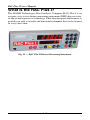
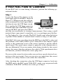
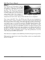
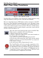
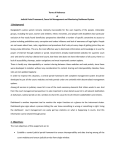
i
RAC Plus I User’s Manual
WARNING
Use of the RAC Plus I while driving could cause an accident, resulting in serious injury
or death. As with any in-vehicle instrumentation, the information provided by the RAC
Plus I should be observed as part of the normal operation of the vehicle. Changes to the
RAC Plus I should only be done in a safe manner.
Installation of the RAC Plus I and distance sensor should be done with caution so it
does not cause unsafe conditions.
DO NOT mount the RAC Plus I where it will obstruct the driver's view.
DO NOT mount the RAC Plus I over or near an air bag.
DO NOT route cables in a manner that would interfere with operation of the vehicle.
LIMITED WARRANTY
JAMAR Technologies, Inc. warrants the RAC Plus I for a period of five (5) years limited
warranty against defects in material and workmanship as follows: first year, parts and
labor; years two through five, parts only, flat labor charge. Sensors, cables, connectors,
brackets and other hardware are warranted for ninety (90) days.
JAMAR Technologies, Inc. warrants each new instrument manufactured by the company
to be free from defective material and workmanship and agrees to remedy any such defect.
At its option, it may furnish a new part in exchange for any part of any instrument of its
manufacture which, under normal installation, use and service discloses such defect. The
instrument must be returned to the JAMAR factory or authorized service agent intact,
for examination, with all transportation charges prepaid.
This warranty does not extend to any products which have been subject to misuse,
neglect, accident, incorrect wiring not our own, improper installation or use in disregard
of instructions furnished by JAMAR. This warranty does not extend to products which
have been repaired or altered outside the JAMAR factory or authorized service agent.
In no event shall JAMAR Technologies, Inc. be liable for any damages arising from the
use of this product including damages arising from the loss of information.
This warranty is in lieu of all other warranties expressed or implied and no representative
or person is authorized to assume for JAMAR Technologies, Inc. any other liability in
connection with the sale or use of JAMAR products.
JAMAR Technologies, Inc. reserves the right to make improvements on the product and/
or specifications at any time without notice. Questions concerning this warranty or any
JAMAR Technologies, Inc. product should be directed by e-mail, mail or telephone to:
JAMAR Technologies, Inc.
1500 Industry Road, Suite C, Hatfield, PA 19440
215-361-2244 • [email protected]
Copyright 2012 by JAMAR Technologies, Inc.
ii
Table of Contents
We are pleased that you have chosen the RAC Plus I for your distance measuring
needs. We have strived to develop a unit that is easy to use and has the options that
our customers require. The RAC Plus I has undergone extensive testing to verify
the accuracy of its operations, and each unit is tested before it leaves our facility.
However, just like other complex electronic devices, problems can occur. We always
suggest that users verify the continuing accuracy of any device they use. Should you
detect any problems with any of our products, please notify JAMAR Technologies
immediately and discontinue use of the unit until we have verified its operation.
If you have any questions about the use of the RAC Plus I, please call the
following number:
1-215-361-2244
Monday — Friday, 8:00 AM to 5:00 PM Eastern time
You may also contact us by e-mail at:
[email protected]
For more information on our products, or for the latest news in product
development, visit our web site at:
www.jamartech.com
For support information specific to the RAC Plus devices, go to:
www.jamartech.com/RACPlusSupport.htm
Address any correspondence to:
JAMAR Technologies, Inc.
1500 Industry Road, Suite C
Hatfield, PA 19440
Volume 2.4 November 2012
iii
RAC Plus I User’s Manual
Table of Contents
Technical Support
Quick Start Guide
............................................................ iii
..............................................................v
Introduction to the RAC Plus I.......................................................... 1-1
What is the RAC Plus I? . ........................................................ 1-2
How Does It Work?
.......................................................... 1-3
Installation
.......................................................... 2-1
Before You Begin
.......................................................... 2-2
Installing the OBD Distance Sensor........................................ 2-3
Installing the Modular Distance Sensor................................... 2-6
Installing the Magnetic Distance Sensor............................... 2-10
Installing the RAC Instrument............................................... 2-15
Calibration
.......................................................... 3-1
Automatic Calibration Procedure............................................ 3-2
If Your RAC Fails to Calibrate................................................. 3-5
Manual Calibration Procedure................................................. 3-7
Key Functions & Operating Procedures........................................... 4-1
RAC Plus I Key Functions....................................................... 4-2
RAC Plus I Menu Functions.................................................... 4-5
RAC Plus I Additional Features............................................. 4-10
Troubleshooting
.......................................................... 5-1
Frequently Asked Questions.................................................... 5-2
Appendix
......................................................... A-1
RAC Plus I Specifications....................................................... A-2
Power Connection Wiring....................................................... A-3
Glossary
......................................................... A-4
Vehicle Calibration Record..................................................... A-6
iv
Quick Start Guide
The RAC Plus I DMI will allow you to accurately measure distance quickly
and easily. However, before you can do this a few basic steps must be taken
to ensure that you get the optimum performance from your instrument.
Step 1
Install your RAC and its distance sensor. Refer to Chapter 2 for detailed
instructions on this. If you would like to have the equipment professionally
installed, contact a garage or speedometer shop in your area.
Step 2
Calibrate your instrument. Refer to Chapter 3 for detailed instructions on
how this is done. Your RAC will not accurately measure distance unless
it is properly calibrated.
Step 3
Perform a test measurement with your vehicle. Once your RAC has been
calibrated, you should perform a test measurement over a known distance.
This will ensure that the instrument has been calibrated correctly.
To do a test measurement, drive to your starting point and stop. Turn on the
RAC and wait until zero is shown on the larger, upper display and CH is
shown on the smaller, lower display. Next, press the CH (count hold) button
to release the instrument from count hold and then drive the distance to be
measured. Stop and/or press the CH button once you reach the end of the
distance to be measured.
Step 4
Familiarize yourself with the features and options of the instrument that
you will be using. Refer to Chapter 4 for more detailed instructions on the
functions and procedures of the RAC Plus I.
Step 5
Practice. Before attempting to use the instrument on a job, be sure you are
comfortable with how to operate it.
v
RAC Plus I User’s Manual
vi
Chapter 1 — Introduction to the RAC Plus I
Chapter 1
Introduction
to the
RAC Plus I
1-1
RAC Plus I User’s Manual
What is the RAC Plus I?
The JAMAR Technologies Road Analysis Computer (RAC) Plus I is an
accurate, easy-to-use distance measuring instrument (DMI) that uses stateof-the-art microprocessor technology. It has been designed with features to
provide you with a versatile and functional instrument that can be learned
in a very short time.
Fig. 1.1 — RAC Plus I Distance Measuring Instrument
1-2
Chapter 1 — Introduction to the RAC Plus I
How does it work?
The RAC Plus I is installed in your car along with a distance sensor.
Distance sensors do the behind-the-scenes work of the RAC Plus distance
measuring instruments. Connected between your vehicle and the RAC Plus
head unit, these sensors read and modify the data coming from your vehicle
and send a signal to the RAC telling it when to count distance.
There are currently three types of distance sensors that are used with the
RAC Plus I – the AutoLink OBD sensor, the modular sensor and the magnectic sensor.
Why are there three types? Because distance measuring instruments are
used by a wide variety of customers who often have different needs and in
a wide variety of vehicles that don't all work the same.
The simple breakdown of the three is that the AutoLink sensor is the newest and easiest to install (plug and play, no tools required), but that ease of
install trades a degree of accuracy. The magnetic sensor is the most precise,
but much more intensive to install than the AutoLink, while the modular
sensor has accuracy similar to that of the magnetic sensor and is somewhat
easier to install, but is not compatible with all vehicles.
The next chapter details how to install these various sensors into your
vehicle. If your already have a sensor installed, you may skip to Chapter 3
for information on calibrating your RAC.
1-3
RAC Plus I User’s Manual
1-4
Chapter 2 — Installation
Chapter 2
Installation
2-1
RAC Plus I User’s Manual
Before You Begin
The JAMAR RAC Plus I distance measuring instruments are very reliable.
However, there can be some external variables that could affect proper operation and the ability to accurately measure distance traveled. By observing
a few simple precautions you will be able to eliminate potential problems.
• Do not install wires near any object that could cause stray pulses to
be picked up, such as the alternator, spark plugs or engine coil.
• Do not install the wires or sensor near any objects that will get hot,
such as the manifold. The installation wires or sensor can melt if they
are too close to a heat source.
• Do not install wires near any objects that could vibrate and cut the
wires.
• Tire pressure should be the maximum suggested by the tire manufacturer, typically 32-35 PSI cold. The tire should have ample tread
depth. Steel belted radial tires are highly recommended.
• Drive the vehicle 3 to 5 miles (depending on climate) to warm the
tires up to normal operating temperatures prior to calibrating your RAC.
Refer to Chapter 3, Calibration for more detailed instructions.
2-2
Chapter 2 — Installation
Installing the OBD Distance Sensor
These instructions are for installing a RAC Plus I with an OBD Distance
Sensor. If you are installing a different type of sensor, skip this section.
The AutoLink allows connection between the On-Board Diagnostics (OBD)
connector in your vehicle and the RAC Plus Distance Measuring Instrument.
Note: Your RAC and vehicle should be turned off while plugging in the
AutoLink cables.
Step 1
Plug the large OBD cable attached to the AutoLink II into the vehicle
OBD connector. The OBD connector is typically found under your dash
near your steering wheel column.
Fig. 2.1 – Plugging in to the OBD Port
Step 2
Connect the grey telephone-style cable from the AutoLink II to the
RAC Plus Power (PWR) port.
Fig. 2.2 – Connecting the OBD Sensor to the RAC Plus I
2-3
RAC Plus I User’s Manual
!
IMPORTANT: Note that the supplied grey telephone-style
cable is the ONLY cable that should be used. DO NOT use
any other cables that may have been provided with your RAC
as you may damage your RAC or the AutoLink.
Step 3
Now that the AutoLink II and the RAC are connected, start your
vehicle. Next, turn on the RAC and the AutoLink II LED lights will
begin flashing.
At this point, the Lock green LED will stay on and remain steady. A steady
green Lock LED indicates the AutoLink II is communicating with, and is
locked onto, the OBD signals coming from the vehicle computer.
The yellow “OBD Tx and Rx” LED lights confirm the transfer of information between the OBD and the AutoLink II. Note that on 2010 and newer
vehicles the LEDs will flash very rapidly and may appear to be on constantly;
this is normal.
The self-adhesive mounting tabs and the tie wraps included can be used to
secure the OBD and the telephone-style cable as desired.
Step 4
Calibrate the RAC as described in Chapter 3. You are then ready to
start collecting data.
For Best Results
• OBD speed signals are generally not available below 1 MPH. As such, the
AutoLink II is not recommended for use where the vehicle may be traveling at ‘creeping’ speed for any length of time. Recording short distance
nodes within a longer course using a stop and go method can result in less
accurate data. This is a function of extreme low speeds introduced during
starting and stopping. In these cases we recommend you use an alternative
sensor type, like a magnetic sensor, for higher accuracy.
• Note that while the vehicle is in motion the RAC and the AutoLink II
will have a small time lag while recording distances into memory. Also
note there will be a final buffered distance on the RAC once the vehicle is
fully stopped.
2-4
Chapter 2 — Installation
• After using your RAC, you should turn off the RAC while your vehicle is
not being used. Power consumption of the RAC display, although minimal,
may drain your battery if the vehicle is idle for an extended time with the
RAC connected and turned on. This is particularly true if your battery is
in poor condition.
• The AutoLink II is turned on and off by the RAC’s power switch and
as such can be left connected to the OBD port while not in use. Note that
this was not the case with the original AutoLink I. The AutoLink I should
always be disconnected from the OBD when not in use.
2-5
RAC Plus I User’s Manual
Installing the Modular Distance Sensor
Note: These instructions are for installing a RAC Plus I with a Modular
Distance Sensor. If you are installing a different sensor, skip this section.
1. Find a location under the vehicle
dashboard that will allow fairly easy
access to the MDS. Do Not mount the
MDS on the heater ducts or where the
heater vents will blow directly onto it.
Attach the MDS using the nylon ties or
Velcro provided, as shown in Fig. 2.3.
Fig. 2.3
MDS Mounted Under Dash
2. Locate the 2 wires coming from the Vehicle’s Speed Sensor (VSS).
• On most Ford and Chrysler pick-up trucks, the best place is on the
rear end differential housing using the rear ABS signal.
• On GM pick-up trucks, the best place is the VSS at the transmission.
• On many vehicles (both trucks and autos) you can go to the cruise
control signal or to the vehicle ECU which is often located under the
dashboard.
(Note: Vehicle wiring changes from year to year
and model to model. For technical support in locating the vehicle speed signal wire call JAMAR
at 215-361-2244. Your local Auto/Truck dealer
can also usually tell you where the VSS can be
located on your vehicle.)
All wires and the
MDS itself should be
kept away from heat
sources that could
cause melting.
3. Route the red and black end of the 20’ grey VSS
cable through the firewall. This can usually be done by using an existing
rubber grommet where other wires pass through the firewall. If you cannot
locate an existing hole, CAREFULLY drill a small hole large enough for
both the VSS cable and the +12Volt/Ground wires. EXTREME CAUTION
must be taken to insure you do not drill into anything mounted on the opposite side of the firewall or cut any existing wiring.
2-6
Chapter 2 — Installation
Use the cable ties provided while routing the cable to the location for getting
the speed signal that you previously identified. Attach the red wire of the
VSS cable to the high-speed signal wire of the vehicle’s speed sensor using
the tap splice connectors provided. The black wire is for optional use with
vehicles made before 2002. In these vehicles, it should be connected to the
low speed signal wire of the vehicle’s speed sensor or chassis ground. If you
are unsure which wire from the VSS is the high-speed signal and which is
the low-speed signal, pick one and connect the red wire to it. If the RAC
counts when the vehicle moves, you are good to go. If not, connect the red
wire to the other wire from the VSS.
NOTE: The tap splice connectors are supplied for convenience for initial installation. However, we recommend that once the installation is
completed and you have verified the instrument is working properly,
remove the tap splice connectors and solder the connections. Insulate
using electrical tape or silicone.
4. Plug the connector of the VSS cable
into the hole labeled VSS Input located
on the right side of the MDS, as shown
in Figure 2.4.
Fig. 2.4 –VSS Plug-in
5. Route the black DMI cable from the
MDS to the desired instrument location. This will usually be routed between
the doorpost and the dashboard. Make sure the cable will not be pinched
when closing the door. If the instrument is going to be mounted to the front
of the dashboard, you may want to bring the cable straight up the front of
the dash. There is adequate cable length
to allow mounting the DMI in any desired location inside the vehicle. Plug
the cable into the MDS jack labeled To
DMI, as shown in Figure 2.5. It does
not matter which end of the cable is
Fig. 2.5 – DMI Plug-in
plugged into the MDS or DMI.
6. Route the Red (+12 Volts) and Black (Ground) power cables directly to
the vehicle’s battery. This can be done using the same feed through location that was used for the VSS Cable. If, out of convenience, you elect to
obtain the +12VDC and ground from a fuse panel or other location under
the dashboard, make sure it is a constant 12 volt source and not one that
2-7
RAC Plus I User’s Manual
is switched off with the ignition key.
We also recommend the circuit should
have as few devices as possible to avoid
voltage fluctuations from Turn Signals,
Brake Lights, etc. Plug the power cable
into the hole labeled Power on the
MDS, as shown in Figure 2.6.
Fig. 2.6 –Power Plug-in
Adjusting the Vehicle Speed Sensor Pulse Rate
The signal pulses coming from the vehicle speed sensor are generated for
use by the vehicle’s computer, engine/transmission control, fuel management, ABS brakes, etc. The pulse rate can vary from 4,000 to in excess of
100,000 pulses per mile. The MDS will condition and amplify these pulses
for use by the DMI. Since the higher
pulse rates are not required for accurate distance measurements, the MDS
incorporates a divider circuit to reduce
the pulse rate. This is done by adjusting
the rotary switch on the front of the
MDS, as shown in Figure 2.7.
Fig. 2.7
Rotary Switch Adjustment
The adjustments go from 1 to 1 (1 pulse
into the sensor, 1 pulse out) through
64 to 1 (64 pulses into the sensor, 1 pulse out). Although your particular
vehicle may vary, generally Chrysler and Ford vehicles use a 4 to 1 ratio
(position 4 on the switch) while General Motors vehicles use a 16 to 1 ratio
(position 16 on the switch).
To adjust the ratio, use a small screwdriver to turn the switch to align it
with the number you want. Note that the switch is at the '1' position when
switch is turned fully counterclockwise. It is at the ‘Test’ position when the
switch is turned fully clockwise.
The Tap Test positions are explained in the troubleshooting section on page
3-4. You may need to adjust the ratio again based on the results of the calibration procedure described in Chapter 3. Any time you change the pulse
ratio, you will need to re-calibrate the DMI.
Once you have installed the MDS, install your RAC Plus using the instructions on page 2-15.
2-8
Chapter 2 — Installation
Filter Toggle
The number of pulses per mile from a vehicle will vary with the make and model.
Your calibration factor should be between .500 and 1.200. If not, adjust the
rotary switch then recalibrate to reach a calibration number within this range.
The black wire is is for
optional use with vehicles
made before 2002.
Ground Black
+ –
Battery
Filter toggle should always be OFF unless
you are getting ‘noise’ on the speed sensor
line, which causes the RAC to count while
the vehicle is not moving.
Fire
Wall
If the speedometer does not respond to
vehicle movement, simply switch the
RED wire to the other VSS wire.
Black
Fire
Wall
+12 VDC Red
Fig. 2.8 –
Filter Toggle
Red
RAC Connector
As a default, the Filter toggle should be set to ‘Filter
Off’. However, on some vehicles there is ‘noise’ on
the speed sensor line that causes the RAC to count
up while the vehicle is not moving. The filter toggle
should be flipped to ‘Filter On’ in these cases.
Tap Splice
Connector
High Speed Signal
Vehicle Speed
Sensor (VSS)
Low Speed Signal
Most vehicles should have a 2-wire output from the VSS.
Dodge & Ford trucks may have the VSS located on top of the rear end housing instead of at
the transmission. It will normally be a 2-wire output, small gauge wire.
Connect the red wire of the long 20’ VSS cable to the high-speed signal wire of the vehicle’s
speed sensor. (The black wire is for optional use with vehicles made before 2002.) Crimp-on tap
splice connectors are supplied for convenience on initial installation. However, we recommend
removing the tap splice connectors and reconnecting using wire to wire solder once you are
sure all connections to the VSS are proper. Insulate with sealant/electrical tape as needed.
Fig. 2.9 –MDS Installation Diagram
2-9
RAC Plus I User’s Manual
Installing the Magnetic Distance Sensor
Note: These instructions are for installing a RAC Plus I with a Magnetic
Distance Sensor. If you are installing a different sensor, skip this section.
For the installation you will need the Magnetic Sensor Kit shown below.
G
B
F
A
Fig. 2-10
C
D
E
A – Magnets
B – Epoxy
C – Zip Ties
D – Mounting Bracket
E – Hardware Kit
F – Magnetic Sensor
G – Extension Cable
and the Vehicle Installation Kit shown below.
H – Terminal Block
I – Power Cable
J – Ground Cable
K – DMI Connector Cable
L – Velcro
M – Zip Ties
H
L
I
K
2-10
M
J
Fig. 2-11
Chapter 2 — Installation
Once you have finished the following steps, your installation should
look similar to Figure 2-12 below.
Instrument black wire to battery ground and sensor black wire.
Instrument yellow wire to battery +12 VDC and sensor white wire.
Instrument green wire to sensor red wire.
Instrument red wire not used.
Figure 2-12
S
Firewall
Black
S
H
N
Sensor
(Green
body)
F
Black
Epoxy
Magnets to
Drive Shaft,
alternating
polarity.
N
If possible, mount
Terminal Block
under dash inside
vehicle. Otherwise,
mount under hood in
convenient location
(left fender well)
to accommodate
necessary wiring.
S
White
Red
A
S
G
3/8"
nuts
1/4" to 1/2"
air gap
J
I
fuse
D
North and South magnet sets must be evenly
spaced around the drive shaft, at least 1”
apart. Spacing between the North-South sets
is not as critical, but should be uniform.
Ground
+12 VDC
Red
Cut end off of the Extension Cable (or the Magnetic Sensor cable
itself if the Extension Cable is not being used) and strip back the
insulation on the Red, White & Black wires. Attach to the terminal
block as shown.
Step 1 - Installing the Magnets
The number of magnets that must be used depends on the size of your tire and
where you mount the sensor. Most all installations on automobiles or trucks will
require at least six magnets (3 North/South Sets) to be installed. This will provide
3 pulses per revolution of the wheel or drive shaft to be sent to the Distance
Measuring Instrument (DMI).
On tractor or implement wheels the general
rule of thumb is one magnet for each wheel
bolt (minimum of two, and always an even
number). For drive shafts of small wheels
(ATVs), two magnets are usually adequate.
S
Fig. 2-13
N
The magnets provided are marked with a
dashed line on the SOUTH pole side of the magnet, as shown in Figure
2-13.
Always use an even number of magnets, and always alternate the polarities
of the magnets as you go around the wheel hub or drive shaft.
2-11
K
DMI
Connector
45" max.
1 " Minimum
N
Yellow
1 " Minimum
Red
Sensor assembly
must not be mounted
more than 45 from
perpendicular
Green
N
Test magnet should alternately attract and repel.
Magnets are marked
with a dashed line on the
SOUTH pole side.
RAC Plus I User’s Manual
To install the magnets (part A in
figure 1) on the drive shaft, use
the Epoxy (B). Spare magnets are
provided in the Hardware Kit (E)
should they be needed.
South
North
North
South
Test magnet should
alternately attract
and repel.
South
North
(For front wheel drive vehicles,
the magnetic targets should be Fig. 2-14
attached to the inner CV joint, on
the larger section between the rubber boot and the transmission.)
Note that the epoxy provided needs 6-8 hours to cure properly before the
vehicle should be driven. The magnets can come loose and be lost if the
vehicle is driven before the epoxy has a chance to cure. A quicker setting
epoxy can be used if you need to cut down on curing time. Also, the zip ties
(C) can be used to tie the magnets in place after the epoxy dries to make
sure they stay in place.
Mount the first magnet with the SOUTH pole side (dashed line) facing
toward the hub or shaft. Mount the second magnet with the NORTH pole
side facing toward the hub or shaft, as shown in Figure 2-14. A test magnet
should be used after installation to ensure the magnets have been placed
correctly. Pass the test magnet over the installed magnets and it should
alternately attract and repel.
For proper operation, the North
and South magnet sets must be
evenly spaced around the wheel
or drive shaft, at least 1” apart,
as shown in Figure 2-15. Spacing
from one North-South magnet set
to the next set is not as critical, but
should be uniform.
1 " Minimum
S
N
N
1 " Minimum
Fig. 2-15
2-12
S
S
N
1 " Minimum
Chapter 2 — Installation
Step 2 – Attaching the Magnetic Sensor
The Magnetic Sensor (F) is mounted
directly over the magnets as shown in
figure 3. When the wheel or drive shaft
begins turning, a speed impulse is sent
to the DMI every time a magnet passes
by the tip of the speed sensor. For the
speed sensor to operate properly, the
spacing between the magnets and the
tip of the sensor must always remain
constant. Before permanently mounting
any parts, be sure that the location you
have selected will meet the requirements
shown in Figure 7. NOTE: Observe
magnet polarities (see previous section).
Sensor assembly
must not be mounted
more than 45 from
perpendicular
To Figure 8
45" max.
3/8" nuts
Sensor
(Green body)
1/4" to 1/2" air gap
Fig. 2-16
Using the Sensor Bracket (D) provided, locate a nut or bolt on the side of
the transmission, close to the magnets. Attach the bracket to the transmission using the hardware . (You may have to drill a larger hole in the
sensor bracket to allow proper fitting over the selected bolt/stud.) Bend
the bracket as required so that the Sensor is scanning the targets with a
spacing of about ¼ to ½ inch. The cable coming from the Magnetic Sensor will be used as part of the next step.
The Magnetic Sensor cable has
5 feet of a jacketed 3 wire cable
Black
Black
Yellow
White
Green
Red
Red
Firewall
+12 VDC
If possible, mount Terminal Block under dash
inside vehicle. Otherwise,
mount under hood in
convenient location (left
fender well) to accommodate necessary wiring.
fuse
Mount the Terminal Block (H)
provided with the Vehicle Installation Kit under the dash inside
the vehicle, if possible. If it is not
possible to mount it inside the
vehicle, mount on the driver’s
side fender well or other convenient location. The terminal
block can be mounted using the
Velcro provided.
Instrument Connector
Ground
Step 3 - Installing and
Wiring the Terminal Block
Red
Fig. 2-17
Instrument black wire to battery ground and sensor black wire.
Instrument yellow wire to battery +12 VDC and sensor white wire.
Instrument green wire to sensor red wire.
Instrument red wire not used.
2-13
RAC Plus I User’s Manual
with a water tight plug on the end. There is also a heaver wire Extension
Cable (G) 10 feet in length. This will allow you to use up to 15 feet of wire
for the installation from the magnetic sensor location to the terminal block.
Depending on where you have attached the magnetic sensor (Front Wheel
CV Joint or Rear Wheel Drive Shaft) and the location of the terminal block,
you may or may not need the extension cable.
If the extension cable is needed, plug the extension cable into the magnetic
sensor cable using the water tight connector, then cut the extension cable
to the required length, strip back the insulation on the Red, White & Black
wires and attach to the terminal block as shown in Figure 2-17. Each wire
should be connected to a separate terminal on the block.
If the extension cable is not needed, cut the plug off the end of the smaller
magnetic sensor cable, strip the wires and attach to the terminal block as
shown in Figure 2-17.
Once the magnetic sensor has been properly connected to the terminal
block, connect the terminal block to the vehicle’s battery using the black
and red cables provided.
The RED wire with the in-line fuse (+12VDC) should be connected to the
POSITIVE terminal on the battery and to the same location on the terminal
block as the red wire from the magnetic sensor. The BLACK wire (Ground)
should be connected to the NEGATIVE terminal on the battery and to the
same location on the terminal block as the black wire from the magnetic
sensor.
Finally, connect the DMI Connector Cable (K) to the terminal block as
follows:
• Connect the black wire to the battery ground and sensor black wire.
• Connect the yellow wire to the battery +12 VDC and sensor white wire.
• Connect the green wire to sensor red wire.
The red wire from the DMI connector cable is not used.
Once these steps are complete, you may connect the RAC itself.
2-14
Chapter 2 — Installation
Installing the RAC Instrument
The compact case design of the RAC Plus allows mounting of it in a number of convenient locations. Popular locations include on the front of the
dashboard, above or below the dashboard, or on the windshield using the
optional windshield mounting bracket. Wherever you decide to mount the
instrument, remember it should be within easy reach and the display should
be visible without obstructions.
Note: In extremely hot conditions, do not leave the RAC Plus on the
dash when it is not in use.
It is most common to mount the RAC
to the front of the dashboard using
the Velcro provided. Two plastic 'L'
brackets are also provided to facilitate
mounting to the top of the dashboard if
that is your preferred location. For best
results, attach the 'L' bracket so that the
bottom of the 'L' is facing away from
the RAC as shown in figure 2.8.
Fig. 2.8 - 'L' Bracket Side View
Using the two 'L' brackets allows you to compensate for curved dashboards
even if it requires the RAC to be mounted on a left or right slope.
Fig. 2.9 - 'L' Bracket on Curved Dashbaord
After mounting the RAC, plug the black cable from the MDS into the RAC.
You may want to consider allowing enough slack in the cable to permit a
passenger to hold/operate the RAC if necessary. Regardless of the mounting
location, Velcro strips are provided for quick, easy mounting & removal
of your RAC.
2-15
RAC Plus I User’s Manual
Once you have mounted your RAC and connected it to the distance sensor,
proceed to the calibration instructions in the following chapter.
2-16
Chapter 3 — Calibration
Chapter 3
Calibration
3-1
RAC Plus I User’s Manual
Automatic Calibration Procedure
In order to accurately measure distance, your RAC Plus must know the exact
distance that the vehicle will travel based on pulses from the vehicle's speed
sensor. The calibration number is the automatic calculation that represents
the number of pulses received over a set distance. This number, once calculated, will remain accurate until a change to
Your RAC Plus must the vehicle occurs, such as different size tires are
be calibrated in
put on the vehicle, tire wear, tire pressure change,
order to accurately etc. Such changes will require a re-calibration in
measure distance.
order to maintain proper accuracy.
The RAC Plus has the ability to store four (4) separate vehicle calibration
numbers in memory. This simplifies sharing one instrument between up to
four different vehicles.
In order to calculate the calibration number for your particular vehicle, you
must first establish a calibration course. The length of the course can be
any known distance more than 500 feet. One thousand feet is ideal, but the
course can be any distance over 500 feet (for example, 623 feet from pole
to tree). Your course should be straight and accurate, so take the time to
measure the course using a 100' tape or hand wheel. Mark the beginning and
ending points so they can be seen from inside your vehicle. Remember, the
course length can be any accurate distance over 500 feet, so for convenience
you could use a telephone pole or other marker as reference point.
Note: If you are using the Metric unit of measuring, laying out the
calibration course in feet is required to obtain the most accurate calibration number.
Step 1
Slide the ON/OFF switch to ON. Your
RAC will perform a brief Self Test.
The current calibration number will
be shown in the larger, upper display
(D-1) and CF U(vehicle 1, 2, 3 or 4) in
Fig. 3.1
the smaller, lower display (D-2). This is Calibration Display on Start-up
displayed for 3-4 seconds while a tone
sounds, then 0 is shown in D-1 (0.000 if the mile or meter unit of measurements is selected) while CH is shown in D-2.
3-2
Chapter 3 — Calibration
Step 2
Press the Menu key, the # 1 key and
Enter. At this point, the unit of measurement will automatically change to
feet. You can then select the vehicle
number that this calibration will be
for by using the 1 through 4 numeric
keys.
Fig. 3.2
Vehicle Number Selection
Step 3
Once the vehicle number has been selected, press Enter. Key in the course
length (in feet) to be used for the calibration using the number keys, then
press Enter again.
Fig. 3.3 - Enter Course Length
Step 4
Using a reference point on your vehicle (i.e. the window post, door handle,
your shoulder, etc.), align your vehicle to the beginning course marker.
Step 5
Press the CH key and drive away. As you drive,
If your RAC does
the pulses received from the vehicle are being
not
count during the
shown in D-1. This is not the distance being
calibration procedure,
traveled, so don't panic when the display doesn't
refer to the troubleequal the actual length of your calibration course. shooting section on the
When you reach the end of the course, stop your
next page.
vehicle so you are exactly aligned (using the same
reference point in the vehicle) with the end course marker.
Step 6
Press the CH key. The calibration factor
will then be shown in D-1. You should
record the calibration number, vehicle
number and date in the Appendix of this
manual on page A-7. It is also recomFig. 3.4
mended that you put this same informaCalibration Number Displayed
tion on a piece of tape attached to the
inside of the vehicle's glove box. Proceed to Step 7 on the next page.
3-3
RAC Plus I User’s Manual
Step 7
Press Enter and the unit of measurement will return to your desired unit of
feet, mile or meter. Press Enter again to exit the menu function and return to
normal operation. Your calibration number for the vehicle selected is now
stored in the RAC's nonvolatile (permanent) memory. The calibration number will stay in memory for more than 50 years, or until you re-calibrate or
manually change the data. You are able to view the calibration number and
unit (vehicle) number every time you power up the RAC.
You should rerun the calibration course, in the normal mode, to verify the
calibration for your vehicle. Press the CH key prior to measuring. If this is
the first time you have calibrated a DMI, you may want to run the course a
couple of times to practice being properly aligned when starting and stopping at the course markers.
Important: Ideally, the calibration number used
should be between .500 and 1.200. If your calibra- Your calibration
tion number is below this range, you need to use a number should
higher division factor such as 16 on the Modular ideally be between
Distance Sensor (MDS). Of course, if your calibra- .500 and 1.200. If
not, you can adjust
tion number is too high, you can lower the number
the rotary switch on
by using a lower number such as 1 on your MDS. the modular sensor.
This is done by adjusting the rotary switch on the
MDS so the slot points to 1, 2, 8, 16, 32 or 64.
Note: The adjustable rotary switch is only available on Modular Distance
Sensors. If you are using an OBD or Magnetic sensor there is no adjustment to be made.
Any time you adjust the rotary switch setting, you must re-calibrate to
get the correct calibration number. Changing the switch setting will not
change the calibration number, only the number of pulses being received
by the RAC.
Refer to the Adjusting the Vehicle Speed Sensor Pulse Rate section in Chapter 2 for more information on this. Several calibration runs may be necessary
to determine which division factor is best for your vehicle.
3-4
Chapter 3 — Calibration
If Your RAC Fails to Calibrate
If your RAC fails to count during calibration, perform the following operational checks:
Step 1
Locate the Sensor Test button on the
front upper right of the MDS, shown in
Figure 3.5. When pressed, this will generate an internal low-level signal that is
fed directly into the VSS Input circuit.
First, unplug the VSS Input connector
from the right side of the MDS. Second,
Fig. 3.5 – Sensor Test
turn on the RAC and press the CH key
just like you would prior to starting a measurement. Next, using a small
pointed object (pen, pencil, screwdriver, etc.) or your finger press the Sensor Test button for a few seconds. The RAC should count when the button
is pushed. What number it counted doesn’t matter as long as it did count.
If the RAC did count, everything from the MDS up to the RAC is okay and
the problem is most likely either a poor connection at the vehicle’s speed
sensor or the connection is not at the correct location to get the vehicle
speed signal. The speed sensor output is generally at the transmission or
the rear differential. If you are unsure about being attached to the correct
output, disconnect the plug and move the vehicle. If the speedometer does
not function, you have chosen the correct plug wires.
If you are at the correct location, make sure you have a good electrical connection at the tap in point. Once you are sure you tapped into the correct
location, it is always better to wire solder the connection.
After checking the connection, plug the VSS Input connector back into
the MDS and try the RAC again. If the RAC counts, you can proceed with
calibration. If the RAC still does not count, go to Step 2.
3-5
RAC Plus I User’s Manual
Step 2
The Tap Test will determine if the distance pulses being sent from the MDS
are getting to, and being processed by,
the RAC. The Tap Test is performed
using the rotary switch shown in figure
3.6. First make sure you note the current position of the rotary switch (1, 2,
Fig. 3.6 - Tap Test
4, 8,16, 32 or 64), as you will have to
return the slot back to this same position after the test is completed.
Next, turn on the RAC. Press the CH key just like you were beginning to
measure. Using a small screwdriver, rotate the switch between the Tap and
Test positions four or five times. (Note that when the switch is turned clockwise until it stops, it is at the Test position.) The RAC should register. The
count shown does not matter, just as long as the RAC did register a count.
If it did count, the cable from the MDS to the RAC and the instrument itself
are OK. If the RAC did not count, the problem is most likely a bad cable to
the RAC or the RAC itself is bad. If available, try another RAC and repeat
the Tap Test. If the second RAC doesn’t count, the problem has to be the
cable between the MDS and the RAC.
Once the test is complete, return the Rotary Switch to the previous position.
If the previous steps do not correct the problem, contact us using the information on page iii.
3-6
Chapter 3 — Calibration
Manual Calibration Procedure
It is very common to share one RAC on a plug-in basis between a number
of different vehicles that have been equipped to accept the instrument.
Installing additional vehicle kits on other vehicles is an inexpensive and
cost effective means to greatly expand your measuring capabilities. Obviously, each vehicle so equipped would have to be calibrated and the number
recorded.
The RAC Plus has the unique ability to store in memory four (4) different
vehicle numbers and their associated calibration numbers. If you are moving
the RAC from vehicle to vehicle you will need to enter the correct vehicle
(unit) number prior to measuring with that vehicle. The following procedure
assumes the calibration number for a particular vehicle has already been
determined and is stored in memory.
Step 1
Slide the ON/OFF switch to ON. The
RAC Plus will complete a brief Self
Test during which a tone will sound
and the active calibration number will
be displayed in D-1 while the vehicle
number is displayed in D-2. After the
self test, 0 is shown in D-1 (0.000 if the
mile or meter unit of measurements is
selected) while CH is shown in D-2.
Fig. 3.7
Calibration Display on Start-up
Step 2
Press the Menu key, the #2 key and
Enter. You can then select the vehicle
number for the calibration that you
wish to change by using the 1 through
Fig. 3.8
4 numeric keys. If all you want to do
Vehicle Number Selection
is change the active vehicle number,
press Enter and go to Step 5. If you want to change the calibration factor,
proceed to Step 3.
3-7
RAC Plus I User’s Manual
Step 3
Press the Enter key and the current calibration number for the vehicle selected
will be displayed. Press the Clear key
(CLR) to clear the current number.
Fig. 3.9
Calibration Number Cleared
Step 4
Using the numeric keys, key in the desired calibration number for the vehicle
selected.
Step 5
Fig. 3.10
Press Enter to return to the initial menu
New Calibration Number Entered
screen, then press Enter again to exit
the menu function. The new vehicle number and/or calibration number is
stored in memory and the RAC is back to normal measuring mode.
Once your DMI is properly installed and calibrated, you are ready to
begin accurately measuring distance.
3-8
Chapter 4 — Key Functions & Operating Procedures
Chapter 4
Key Functions &
Operating
Procedures
4-1
RAC Plus I User’s Manual
RAC Plus I Key Functions
Fig. 4.1 — RAC Plus Key Layout
Your RAC Plus series DMI has been designed for simple operation, using
large individual keys which provide a click and tone feedback.
The two 6-digit high-intensity LED display windows (exclusive to the RAC
Plus series) allow flexibility in displaying data to you. The upper, larger
display window (referred to as D-1) is primarily used to display distance. It
is also used to indicate menu locations and time. The lower, smaller display
window (referred to as D-2) is used to display count status, speed, interval
distance, menu descriptions, etc.
This is the slide switch which provides power to the RAC Plus.
When turned on, the RAC will do the following:
1. Initiate internal Self Test sequence.
OFF/ON 2. Display calibration number in D-1 and vehicle number in
D-2, along with a 3 second tone.
3. Set itself in Count Hold with CH displayed in D-2.
4. Set the unit of measuring (feet, mile, meter) and the vehicle
number to be the last one used when the RAC was turned off.
5. Set itself to count up.
6. Set the Distance Pulse Output interval to zero.
Count
Hold
The Count Hold key will start or stop the computation of distance pulses. When in Count Hold, CH will be displayed in
D-2 and the RAC will not accumulate any distance. If speed is
also being displayed, it will continue as CH does not stop the
computation of vehicle speed. When released, CH in D-2 will
go out and distance computation will resume.
4-2
Chapter 4 — Key Functions & Operating Procedures
Display Hold will stop the display from updating while the
RAC will continue to accumulate distance internally. When
in Display Hold, DH will be displayed in D-2. If speed is also
Display being displayed, it will continue as DH does not freeze the
Hold
speed display. Note: You cannot put the RAC in both Count
Hold and Display Hold at the same time. Count Hold will take
precedence over Display Hold.
Unit
Speed
Menu
The Unit key allows you to select the desired unit of measurement. This can be selected/changed while moving or at rest.
When pressed, the distance will cycle from total feet to miles to
kilometers/meters. The LEDs to the left of D-1 indicate which
unit is currently being used.
The Speed key allows you to turn on or off the display of speed
(mph or kph) in D-2. The display of speed is not interrupted by
either the Count Hold or Display Hold keys.
The Menu key allows you to select from a variety of functions. After pressing the Menu button, the Add and Sub keys
can be used to scroll through the options, which are displayed
in D-2. To select an option, press the ENT (Enter) key. The
options are:
Menu 1 - Auto Calibration (A-CAL)
Menu 2 - Manual Calibration (E-CAL)
Menu 3 - Pre-Distance (P-diS)
Menu 4 - Clock Set (CLoSEt)
Menu 5 - Distance Pulse Output (dPO)
Menu 0 - Return to Normal Operation (rEturn)
See pages 4-5 to 4-9 for specific menu instructions.
Add
The Add key instructs the RAC to count up. It is also used in
the Menu function to scroll up through the various options, and
is used in the Pre-Distance function.
4-3
RAC Plus I User’s Manual
The Sub key instructs the RAC to count down. When in this
mode, the LED indicator for the active unit of measurement
will flash to indicate that you are subtracting distance. Should
Subtract you count down to zero (0), the RAC will provide a tone and
automatically begin counting up.
The Sub key is also used in the Menu function to scroll down
through the various options, and is used in the Pre-Distance
function to subtract a desired distance from the displayed
distance.
Dim
The Dim key allows you to select from four (4) levels of display
brightness to best suit the ambient light conditions. Full bright
is best for daylight conditions while full dim may best suit night
conditions. Each time the Dim key is pressed, the brightness
will drop one level until the lowest level is reached. It will then
jump back to the high brightness level. Both D-1 and D-2, as
well as the LED indicators, are controlled by the Dim key.
Clear
The Clear key is normally used to clear the D-1 distance display
as well as the Interval Distance in D-2 if that function has been
selected. Clear can be used on the run (while measuring), which
allows you to establish a zero starting point without having to
stop your vehicle in traffic or the center of a busy intersection.
Clear will not reset the Time Counter in normal mode.
Enter
Numbers
0-9
The Enter key instructs the RAC to accept the previously keyed
value currently on the display. It is also used in the Menu function and Interval Distance application.
The numeric keys are used to identify menu options and select
numbers desired for calibration, pre-distance, distance pulse
output, clock set, etc.
4-4
Chapter 4 — Key Functions & Operating Procedures
RAC Plus I Menu Functions
The Menu key of the RAC allows you to select from a variety of functions.
After pressing the Menu button, the Add and Sub keys can be used to scroll
through the options, which are displayed in D-2. To select an option, press
the ENT (Enter) key.
Menu 1 & 2 - Calibration Procedures
Refer to Chapter 3, Calibration, for full details on calibration procedures.
Menu 3 - Pre-Distance
The Pre-distance feature will allow you to enter a known distance starting
point other than zero. It could be where you left off before lunch, or just
beginning at a known station. This feature also allows you to Add or to
subtract off a distance currently on display in D-1.
Note: The RAC must be in Count Hold to use Pre-Distance.
Step 1
Press the Menu key, the #3 key then
the Enter key. At this point, the unit is
ready to have a distance entered.
Fig. 4.2 — Enter Pre-Distance
Step 2
Using the numeric keys, key in the
desired distance (up to 6 digits), then
press Enter.
Fig. 4.3 — Distance Entered
Step 3
Press Enter to return to the initial menu
screen, then press Enter again to exit
the menu function. You are now back
in the normal mode with the distance
set to the value you entered.
Fig. 4.4
Note: If you just want to add to the
Normal mode w/ Pre-distance set
distance already on display in D-1, in
Step 2, rather than pressing Enter, press the Add key. To subtract from the
current distance, press the Sub key.
4-5
RAC Plus I User’s Manual
Menu 4 - Clock Set
The RAC Plus will compute & display time as either elapsed time from
when the instrument was powered up, or real time if the timer has been set.
The timer starts automatically at zero when the RAC is powered-up. Time
is displayed in D-1 as hh.mm.ss.
To View Elapsed Time:
Press the Menu key, then the #4 key,
then the Enter key. D-1 shows the
elapsed time since the RAC was powered on. At this time you can stop and
reset the timer with the CLR (clear)
Fig. 4.5 — Elapsed Time
key or just let it continue to run. To
return to normal mode, press the Menu key then the Enter key.
To Set Timer to Real-Time:
Step 1
Press the Menu key, then the #4 key, then the Enter key. D-1 shows the
elapsed time since the RAC was powered on, as shown in Figure 4.6
above.
Step 2
Press the Clear key. Using the number
keys, key in the time you wish to display (hh.mm.ss format). This can be
either 12 or 24 hour format (i.e 1 PM
= 13 hrs).
Fig. 4.6 — Clock Time Entered
Step 3
Wait until the keyed in time is reached
and press the Enter key to begin the
clock counting.
Step 4
To return to normal mode, press the
Menu key then the Enter key.
4-6
Fig. 4.7
Counting from Entered Time
Chapter 4 — Key Functions & Operating Procedures
Note: To view the Clock/Timer while in the normal measuring mode (not
as a Menu function), press the #1 key. D-1 will then display the clock/timer
in hh.mm.ss format. Press the #1 key again to toggle back to distance. This
function does not interrupt the distance count.
IMPORTANT: Once the RAC is turned off, the clock/timer shuts off and
will reset to zero on the next power up. Also note that the Count Hold does
not stop the clock/timer.
Menu 5 - Distance Pulse Output (DPO)
Note: Use of the Distance Pulse Output feature with a Modular Distance
Sensor (MDS) requires a factory modification to the MDS. Contact us using
the information on page iii if you need to use this feature with an MDS.
When activated, the distance pulse output (DPO) will provide a +5 VDC
(TTL level) output pulse at a pre-selected distance interval and signal duration. This low level signal is provided on the red wire in the power/signal
cable. The +5 VDC signal can be used to send distance pulsed to a computer
or other device that can accommodate low voltage, low current signals.
Should you wish to control a +12 VDC high current device, you will need
our optional DPO Amplifier.
In addition to creating a DPO pulse at the pulse interval, one byte of data is
sent out on the RS-232 communications port. This byte contains an ASCII
'S' at 9600 baud. This capability allows the RAC to effectively signal a PC
or other type of unit at the leading edge of the DPO pulse.
CAUTION: The DPO signal can be used to control potentially hazardous equipment. When activated, the DPO could cycle this equipment at
any time. If you are working with this type of equipment, TURN OFF
the RAC, which will deactivate the DPO signal.
To activate the DPO signal:
Step 1
Press the Menu key, the #5 key, then
the Enter key. At this point, the RAC
is ready to have an interval distance
entered.
4-7
Fig. 4.8 — Enter DPO Distance
RAC Plus I User’s Manual
Step 2
Using the numeric keys, enter the
interval distance that you want the
DPO signal generated, based on your
selected unit of measurement (feet,
mile, meter).
Fig. 4.9 — DPO Distance Entered
Step 3
Press the Enter key and you will be
prompted to enter how long the DPO
signal should last. You can key in a
desired signal duration from 10 milliseconds (key in 1) to 2.55 seconds (key
in 255). Keep in mind that if you select Fig. 4.10 — Enter DPO Duration
a long output duration your signals may
run together at high speeds. A 10 millisecond pulse duration is usually
adequate for sending pulses to a laptop computer and will not overlap at
normal highway speeds.
Step 4
Press Enter and you will be prompted
to select whether or not you want an
audible tone to sound when the DPO
signal is triggered. The 1 in D-1 signifies that the tone is on. If you want a
Fig. 4.11 — DPO Tone On
tone with each output pulse, leave 1 in
D-1. If you do not want a tone, enter zero (0) or press the Clear key.
Step 5
Once you have selected whether you
want a tone or not, press Enter. D-2
will then indicate that the DPO signal
has been activated.
Fig. 4.12 — DPO Activated
Step 6
Press Enter to return to the initial menu screen, then press Enter again
to exit the menu function. You are now back in the normal mode with the
DPO signal set.
4-8
Chapter 4 — Key Functions & Operating Procedures
To turn off the DPO signal:
Step 1
Press the Menu key, the #5 key then
Enter. The current DPO interval distance is then displayed in D-1.
Fig. 4.13 — Current DPO Distance
Step 2
Press the CLR (clear) key and the DPO
distance is removed.
Fig. 4.14 — DPO Distance Cleared
Step 3
Press the Enter key and D-2 will then
indicate that the DPO signal has been
deactivated.
Fig. 4.15 — DPO Deactivated
Step 4
Press Enter to return to the initial menu screen, then press Enter again
to exit the menu function. You are now back in the normal mode with the
DPO signal turned off.
Note: When the RAC is turned off, the DPO distance interval duration resets
to zero (0), thereby deactivating the output. If you turn the RAC off, you
must reset this if you want the DPO to be activated again.
4-9
RAC Plus I User’s Manual
RAC Plus I Additional Features
Interval Distance
This feature allows you to determine distance between points of interest,
such as telephone poles, signs, pavement markings, etc. You can activate
Interval Distance at any time as long as you are in the normal measuring
mode and not using the menu functions.
Step 1
To activate the Interval Distance feature, press the #4 key. The INT DIST
LED indicator will then light. D-1 will
be used to show the actual travel distance, while D-2 will be used to show
the Interval Distance.
Fig. 4.28 —
Interval Distance Activated
Step 2
As you pass each reference point,
press the Enter key. D-1 continues to
show overall distance travelled, while
D-2 will lock on the current interval
Fig. 4.29 —
distance. Each time the Enter key is
Interval
Distance Displayed
pressed, D-2 will update to the most
recent interval distance. There is no
limit to the number of times you can use the Enter key to update the interval distance display.
Step 3
To exit the Interval Distance feature, press the #4 key.
Note: If speed is already being displayed in D-2, Interval Distance will take
precedence over speed until the Interval Distance feature is ended.
4-10
Chapter 5 — Troubleshooting
Chapter 5
Troubleshooting
5-1
RAC Plus I User’s Manual
Frequently Asked Questions
Q. My RAC will not count. What’s wrong?
A. In most cases, when a RAC Plus won’t count, it is not the unit itself that
has the problem. It is usually a problem with the interface sensor or wiring.
Check the following:
1. Ensure the RAC has a calibration number in memory. The RAC
will not count if there is not a number in memory. As you switch on the
RAC, the calibration number will be displayed for about three seconds.
The factory uses .900 as the test number. If no number is listed, refer
to the Manual Calibration Procedure on page 3-7 for information on
how to enter a number.
2. Ensure that you are attached to the speed sensor output. It is
generally at the transmission or the rear differential. If you are unsure
about being attached to the correct output, disconnect the plug and move
the vehicle. If the speedometer does not function, you have chosen the
correct plug wires.
3. Perform a Sensor Test. Locate the Sensor Test button on the front
upper right of the Modular Distance Sensor. When pressed, this will
generate an internal low-level signal that is fed directly into the VSS
Input circuit. First, unplug the VSS Input connector from the right
side of the MDS. Second, turn on the RAC and press the CH key just
like you would prior to starting a measurement. Next, using a small
pointed object (pen, pencil, screwdriver, etc.) or your finger press the
Sensor Test button for a few seconds. The RAC should count when the
button is pushed. What number it counted doesn’t matter as long as it
did count.
If the RAC did count, everything from the MDS up to the RAC is okay
and the problem is most likely a poor connection at the vehicle’s speed
sensor. Make sure you have a good electrical connection at the tap in
point. Once you are sure you tapped into the correct location, it is always
better to wire solder the connection.
After checking the connection, plug the VSS Input connector back into
the MDS and try the RAC again.
5-2
Chapter 5 — Troubleshooting
4. Perform a Tap Test. The Tap Test will determine if the distance
pulses being sent from the MDS are getting to, and being processed
by, the RAC. The Tap Test is performed using the rotary switch on the
MDS. First make sure you note the current position of the rotary switch
(1, 2, 4, 8,16, 32 or 64), as you will have to return the slot back to this
same position after the test is completed.
Next, turn on the RAC. Press the CH key just like you were beginning
to measure. Rotate the switch between the Tap and Test positions four
or five times. The RAC should register. The count shown does not
matter, just as long as the RAC did register a count. If it did count, the
cable from the MDS to the RAC and the instrument itself are OK. If
the RAC did not count, the problem is most likely a bad cable to the
RAC or the RAC itself is bad. If available, try another RAC and repeat
the Tap Test. If the second RAC doesn’t count, the problem has to be
the cable between the MDS and the RAC.
Once the test is complete, return the Rotary Switch to the previous
position.
5. If after checking these items the RAC still does not count, contact
us using the information on page iii.
Q. My RAC counts while the vehicle is not moving. What's wrong?
A. There are three possible causes for this.
1. Your wiring may be picking up stray pulses from the vehicle.
This can occur if the wiring is too close to the alternator, spark plugs,
distributor cap or engine coil.
2. Your ground wire may not be connected properly. Double check
its connections.
3. Your Modular Distance Sensor may not be working correctly.
Contact JAMAR using the information on page iii for information on
getting replacement parts.
5-3
RAC Plus I User’s Manual
Q. My RAC will not turn on. What’s wrong?
A. There are two possible causes for this.
1. You may have a loose connection. Double check all connections
at the MDS and RAC to make sure they are tight and at the correct
locations.
2. There may be a problem with the telephone jack on the power/
signal cable. Check to make sure the contacts are not bent.
Q. My RAC counts in increments of 2, 5, 10, etc. What’s wrong?
A. Your calibration number is too high. The calibration number should be
between .500 and 1.200. You can lower the calibration number by adjusting
the rotary switch on your modular distance sensor. Refer to Chapter 2 for
more detailed information.
5-4
Appendix
Appendix
A-1
RAC Plus I User’s Manual
RAC Plus I Specifications
Power: 9 to 16 VDC, negative ground.
Display: Dual 6 digit window, high intensity LED. Separate LED indicators for
unit or measurement and interval distance. Four brightness levels.
Accuracy: +/- 1 foot per mile.
Resolution: 1 foot.
Keyboard: 20 sealed keys, 5 million operation with click & tone feedback. ON/
OFF slide switch.
Speed Display: Three digit 0-999 (mph & kph) displayed simultaneous with
distance.
Time: Elapsed/Real Time (hh,mm,ss).
Count: Bi-Directional (Up/Down).
Calibration: Automatic & manual with four vehicle calibration and vehicle number
ability. Non-Volatile EEPROM Memory.
Test: System check on power up w/display of calibration & vehicle number.
Automatic Distance Conversion: Miles (thousandths) to Total Feet to Meters
(kilometers).
Count Hold: Stops accumulation of distance.
Display Hold: Freezes display without loss of distance.
Pre-distance: Capability of starting at known distance or Add/Subtract desired
distance value from current distance display.
Interval Distance: Display of distance between selected events & total distance.
Distance Pulse Output: 0-5 VDC, low going high, user selectable interval and
duration.
Memory Retention: Non-Volatile EEPROM for calibration & vehicle numbers
— 50+ years retention.
Circuitry: Solid state, surface mount, modular, EEPROM, micro-computer.
Case: ABS plastic.
Dimensions: 7.8"W x 2.3"H x 1.2" D
Weight: 6.5 oz.
Operating Temperature: 0°C to 75°C
Warranty: 5-year instrument warranty.
Example: JAMAR Technologies RAC Plus I
A-2
Appendix
Power Connection Wiring
Pin 1 (Yellow)
Pin 2 (Green)
Pin 3 (Red)
Pin 4 (Black)
+12 VDC
Sensor Input
DPO
Signal Ground
4 3 2 1
A-3
RAC Plus I User’s Manual
Glossary
Refer to the page number listed after each entry for more information.
Add — black button used to count up or add value to the screen on the
RAC. Page 4-3.
Dim — blue button on the RAC, it is used to change the brightness of the
display. Page 4-4.
calibration course — known distance used when calibrating the RAC. One
thousand feet is ideal, but it should not be less than 500 feet. Page 3-2.
calibration number — a number, unique to each vehicle, that represents
the pulses from the transmission received over a set distance. This number
should be as near to 0.500 - 1.200 as possible, and is necessary for the RAC
to count. Page 3-4.
CLR (Clear) — red button on the RAC that resets the distance or time to
zero. Page 4-4.
CH (Count Hold) — red button on the RAC which stops the computation
of distance pulses. Page 4-2.
DH (Display Hold) — red button on the RAC which stops the display, but
allows the RAC to continue accumulating distance internally. Page 4-3.
DMI — generic industry term meaning Distance Measuring Instrument.
The RAC Plus I and Plus II are DMIs.
DPO (Distance Pulse Output) — menu function on the RAC, when activated it will provide a +5VDC (TTL level) output pulse at a pre-selected
distance interval and signal duration. Page 4-7 to 4-9.
EEPROM — stands for Electronically Erasable Programmable Read Only
Memory. It contains the permanent memory of the RAC. Page A-2.
ENT (Enter) — green button on the RAC, it accepts any number keyed
into the display. Page 4-4.
LED — stands for light emitting diode, the display used with the JAMAR
RAC Plus series. Page A-2.
A-4
Appendix
Menu — yellow button on the RAC which is used to access many of its
operation functions. Page 4-3.
Modular Distance Sensor (MDS) – a device which, when installed, conditions pulses from a vehicle’s speed sensor to the RAC. Page 2-3.
nonvolatile memory — the permanent memory of the RAC, it is where the
data and calibration number are stored. It will remain here for fifty years
or more unless changed. Page A-2.
pulses — signals generated by a vehicle which, when conditioned through
a sensor, are read by the RAC to calculate distance traveled. Page 1-3.
pulse rate — the frequency at which pulses are sent to the RAC. They can
vary from 4,000 to more than 100,000 per mile. Page 1-3.
P-Dis (Pre-Distance) — menu function of the RAC, it allows you to enter
a known distance into the RAC. Page 4-5.
RAC — Road Analysis Computer. Brand name for JAMAR’s distance
measuring instruments.
SP (Speed) — black button on the RAC, it allows you to show your speed.
Page 4-3.
Sub — black button used to count down or subtract value from screen on
the DMI. Page 4-4.
Unit — gray button on the RAC, it selects the desired unit of measurement,
from miles to feet to meters. Page 4-3.
A-5
RAC Plus I User’s Manual
Vehicle Calibration Record
Date: _________________________
Date: _________________________
Veh. No: ______________________
Veh. No: ______________________
Cal. Factor: _________________
Cal. Factor: _________________
Veh. Odometer: _______________
Veh. Odometer: _______________
User Initials: ________________
User Initials: ________________
Date: _________________________
Date: _________________________
Veh. No: ______________________
Veh. No: ______________________
Cal. Factor: _________________
Cal. Factor: _________________
Veh. Odometer: _______________
Veh. Odometer: _______________
User Initials: ________________
User Initials: ________________
Date: _________________________
Date: _________________________
Veh. No: ______________________
Veh. No: ______________________
Cal. Factor: _________________
Cal. Factor: _________________
Veh. Odometer: _______________
Veh. Odometer: _______________
User Initials: ________________
User Initials: ________________
Date: _________________________
Date: _________________________
Veh. No: ______________________
Veh. No: ______________________
Cal. Factor: _________________
Cal. Factor: _________________
Veh. Odometer: _______________
Veh. Odometer: _______________
User Initials: ________________
User Initials: ________________
A-6
A-7
RAC Plus I User’s Manual
A-8