1
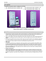
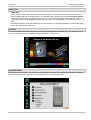
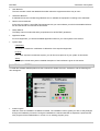
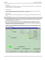
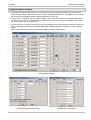
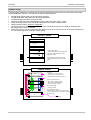
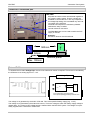
Short Introduction Automotive Test System This document includes a short introduction of the EM TEST automotive test system. For detailed operating information, consult the device and software user’s manuals. emc test equipment Version: Replace: Filename: Date of print: 1.01 1.00 short introduction iso test system V101 21.01.2003 • • • ISO 7637 SAE J1113 Manufacturer spec as GM, Ford, Chrysler, Mercedes, BMW,VW, PSA, Renault, Fiat ...... EM TEST Automotive Test System Test Systems Complete test systems can be configured as follows: Ö 60V / 100A with power mains of 3x400Vac / 32A Ö 60V / 150A with power mains of 3x400Vac / 32A Ö 60V / 50A with power mains of 3x400Vac / 16A Ö 60V / 30A with power mains of 230Vac / 16A Ö 60V / 15A with power mains of 230Vac / 16A Before putting the system into operation, please ensure that the correct power mains supply is available in the test lab Switch On Ö All instruments mounted into the rack system must be switched on. Please check this before switching on the complete system. Open the rack door at the rear and check the power mains switch of the individual instruments. If necessary please switch on the power mains switch and close the door again. Ö Switch on the system by using the central power mains switch at the front of the rack. All instruments are now switched on simultaneously and an internal check-up routine is started to find out which instruments are installed. Ö For the next step please push the Test On button at the front of each instrument. This enables the generator to be ready for testing. The status is shown by the lighted red LED on the front panel. As well as the power mains supply the Test On button must be on for all instruments mounted in the rack. Ö Warning: In case that an instrument is not switched on within the system it will not be realized to be available. Therefore during following test failure messages or fail operations may result. Therefore it necessary to switch on all instruments simultaneously with the central power mains switch. Instruments which will be switched on later are not available for the system because they missed the check-up procedure. Than the complete system must be restarted. Even if the operator does not need all units for a current test it is a better decision to have them all switched on. Ö Failure messages: Depending on the local power mains supply the VDS 200 may show a failure message during the start procedure, Over temperature or Over voltage. The VDS 200 needs a certain inrush current to charge up the internal power capacitors to its specified voltage level. In case that this was not possible and the voltage was too low the switching on procedure must be repeated. For the second time the message should no more appear. Short Introduction V 1.01 2/8 EM TEST Automotive Test System Switch Off Ö Warning: Do not switch off the system during a running test procedure. The instruments may work under maximum load conditions and can not be shut down in a controlled matter. During a running test the Security Switch shall only be used in case of damages at the DUT or in case of personal danger for the operator. For this case please use the Security Switch which is part of delivery. The switch shall be connected to the rear of the rack. Ö Normally the system is switched off after all tests are finished. For switching off please use the central power mains switch at the front of the rack. CD start For more information about the Automotive Test System please insert the enclosed CD in your CD-drive of your PC. If the CD doesn’t start automatically please start the file “iso_d_cd.exe. Documentation In the menu <documentation> you will find more information about your Test System. The information available depends on the acquired system and is structured as shown in the following picture. Short Introduction V 1.01 3/8 EM TEST Automotive Test System • User Manuals The user manuals contain the detailed information about the equipment and the way to use it. • Calibration Manuals If available this section includes the guidelines how to calibrate the equipment according to the standards. • Remote Control Manuals In the case you want to control EM Test equipment with your own software you will find the detailed information and the remote command list in this section. • Safety Manual The safety manual contains the safety requirements for all EM TEST generators. • Application Notes For some equipment, you will find available application notes for your Test System in this section. • System Data Certificates This section contains the certificates of calibration of the acquired equipment. Pictures If you have acquired a racked test system, you will find some pictures of your system in this section. Setup For complex racked test system a detailed description of the interfaces is given in this section. Install Software ISMISO To install the software ISMISO please use the enclosed CD. Select the menu <Software> and the following window will appear. • Install Program With this menu the installation of ISMISO is started. The installation routine guides you with an easy dialogue through the installation procedure. During the installation the relevant data will be expanded, copied and the user program will be installed either in a new or in an existing program group. Short Introduction V 1.01 4/8 EM TEST Automotive Test System • User Manual The user manual is opened with this menu. It contains all the information necessary for a successful configuration and application of the software ISMISO. • Device Licenses This menu contains the license codes for your equipment. To control the equipment with the software you need to enter these license codes in the menu “Device” of your software. • Software Setup This menu contains the most important dialogues for the configuration of the software related to your equipment. Start ISMISO Software Ö Before booting the software on your computer, the test system must be switched on and must be connected via the GPIB (IEEE 488) bus. During the booting procedure the software checks the licenses and after that enables the operator to use the software. Ö Please take notice that the software do not support all GPIB boards which are available on the market. In case of communication problems please contact your responsible service and support center for advice. Please also read the manual of ISM ISO software in which you can find a list of boards being supported by the software. Further information is given in this manual. Ö In case that the operator is starting the software without a test system connected, the operator can use only the demo mode. For complete operation of the software the test system has to be connected and the software has to be restarted. Short Introduction V 1.01 5/8 EM TEST Automotive Test System Configure ISMISO Software Ö For starting the software the first time, it is necessary to enter the necessary licenses for the instruments used. Only instruments, which have a license number can be operated later on. The related license numbers are attached to the ISMISO software package and as a file on the CD. Ö First you have to configure your test system. Open the menu <SETUP><Device> and enter the parameters that are shown in the menu <Software Setup>. Devices which are not in the list, are available via the selection “Search XXX” (for ex. Search EFT). Ö In most cases only one VDS is part of the system and therefore has to be configured as “Battery supply from VDS”. In case that there is a second VDS available this instrument might be configured as an “External dc supply”. Also in most cases there is only one CNA 200 available, which must be enabled. Example Device Setup Example Coupling Network Setup Short Introduction Example DC Source Setup V 1.01 6/8 EM TEST Automotive Test System System Setup The test system is built up in a modular way by using individual instruments which are connected to each other via the GPIB (IEEE 488) bus. The test rack includes the following parts: Central power mains supply for all instruments mounted. Central GPIB (IEEE 488) interface and internal distribution. Complete wiring of the internal control busses. Complete wiring of the rack internal battery supply. (60V/15A // 30A // 50A // 100A) Wiring of the test output of the individual instruments to the central coupling matrix. Single port DUT output, except for Voltage Dip HF–refernce ground system. To this reference ground external ground plane for table top testing or floor standing devices can be connected. External dc sources can be connected at the rear part of the rack. The sources can be remote controlled via a 0-10V analog signal for automatic voltage setting. FRONT VIEW PFS 200B LD 200B MPG 200B Connect: EFT output: - coaxial output EFT to coaxial input CNA EFT 200A + - CNA 200B Central +/- output for the DUT is the output of the CNA Ground reference plane. Connect all units and the chassis of the rack to this plane. VDS 200B REAR VIEW PFS Test supply IN OUT CNA LD MPG EFT CNA Output + - Connect: - output VDS +/- to input CNA +/- output LD +/- to LD input CNA +/- output MPG +/- to MPG input CNA +/- CNA Connect control lines CN: - EFT- CNA to CNA EFT input - MPG- CNA to CNA MPG input - LD- CNA to CNA LD input CNA Connect the GPIB: - Connect all units Ground reference plane All units shall be connected very good to the ground reference system. This is very important for pulse 3a/3b. VDS IEEE bus Short Introduction V 1.01 7/8 EM TEST Automotive Test System Central DUT connection port CNA 200B - All pulses and other events are switched together at this central coupling matrix. There is a single port available to connect the DUT. The only exception is for Voltage Dip testing, this is available only at the direct output of the PFS 200 Automatic test sequences controlled by ISMISO software are easy to realize. - Ground reference connection - The Test On button can be used to switch the DUT supply on and off. Attention: All Test On buttons must be switched. D U T 500mm 50mm Max. 100mm Ground plane External DC Source To simulate the so-called Voltage Dips the use of an external dc source is required. This source is controlled by the PFS 200 via an analog signal of 0 – 10V. Voltage VoltageDip Dip V1 + PF1 + PFS - DUT + PF2 V2 - V1 is the nominal battery supply voltage of the DUT. V2 is the specified dip-voltage (generated by an external dc source. The voltage Vs is generated by the built-in VDS 200. This is the specified battery supply (e.g. 13.5V). The voltage V2 is generated by the external dc source, This is the voltage to which the battery supply voltage is dipped down. The control of this voltage setting is realized within the EM TEST system. The voltage V2 is preferably supplied from a VDS 200 or a RDS 200. Short Introduction V 1.01 8/8