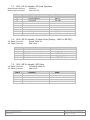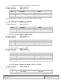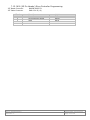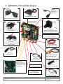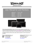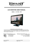
1
User Manual 60SVM10 / 60SVM10-E Dual Channel Audio/Video IP Network Server With 16–bit (BT1120) HD Camera Interface Board 60SVM10 shown Server and I/O board 60SVM shown Server board Prior to Using This Document: Videology reserves the right to modify the information in this document as necessary and without notice. It is the user’s responsibility to be certain they possess the most recent version of this document by going to www.videologyinc.com, searching for the model number, and comparing revision letters on the respective document, located in the document’s footer. For technical assistance with this product, please contact the supplier from whom the product was purchased. Videology® Imaging Solutions, Inc. 37M Lark Industrial Parkway Greenville, Rhode Island 02828 USA Tel: (401) 949 – 5332 Fax: (401) 949 – 5276 North/South American Sales: [email protected] www.videologyinc.com Doc # INS-60SVM10 Revision: C Videology® Imaging Solutions, Europe B.V. Neutronenlaan 4 5405 NH Uden, The Netherlands Tel: +31 (0) 413 256261 Fax: +31 (0) 413 251712 European Sales: [email protected] www.videology.nl Issue Date: 01/16/2014 Page 1 of 38 License Agreement (Software): This Agreement states the terms and conditions upon which Videology Imaging Solutions, Inc. USA and Videology Imaging Solutions, B.V. Europe (hereafter referred to as "Videology®") offer to license to you the software together with all related documentation and accompanying items including, but not limited to, the executable programs, drivers, libraries, and data files associated with such software. The Software is licensed, not sold, to you for use only under the terms of this Agreement. Videology grants to you, the purchaser, the right to use all or a portion of this Software provided that the Software is used only in conjunction with Videology's family of products. In using the Software you agree not to: • Decompile, disassemble, reverse engineer, or otherwise attempt to derive the source code for any Product (except to the extent applicable laws specifically prohibit such restriction); • Remove or obscure any trademark or copyright notices. Limited Warranty (Hardware and Software): ANY USE OF THE SOFTWARE OR HARDWARE IS AT YOUR OWN RISK. THE SOFTWARE IS PROVIDED FOR USE ONLY WITH VIDEOLOGY'S HARDWARE. THE SOFTWARE IS PROVIDED FOR USE "AS IS" WITHOUT WARRANTY OF ANY KIND, TO THE MAXIMUM EXTENT PERMITTED BY LAW, VIDEOLOGY DISCLAIMS ALL WARRANTIES OF ANY KIND, EITHER EXPRESS OR IMPLIED, INCLUDING, WITHOUT LIMITATION, IMPLIED WARRANTIES OR CONDITIONS OF MERCHANTABILITY, QUALITY AND FITNESS FOR A PARTICULAR APPLICATION OR PURPOSE. VIDEOLOGY IS NOT OBLIGATED TO PROVIDE ANY UPDATES OR UPGRADES TO THE SOFTWARE OR ANY RELATED HARDWARE. Limited Liability (Hardware and Software): In no event shall Videology or its Licensor's be liable for any damages whatsoever (including, without limitation, incidental, direct, indirect, special or consequential damages, damages for loss of business profits, business interruption, loss of business information, or other pecuniary loss) arising out of the use or inability to use this Software or related Hardware, including, but not limited to, any of Videology's family of products. Doc # INS-60SVM10 Revision: C Issue Date: 01/16/2014 Page 2 of 38 1. 2. 3. Table of Contents Introduction ....................................................................................................... 5 Document History .............................................................................................. 5 Hardware ........................................................................................................... 6 3.1. Block Diagram ..................................................................................................... 6 4. Inputs/Output ................................................................................................... 7 4.1. Video Inputs ........................................................................................................ 7 4.2. Audio Input ......................................................................................................... 7 4.3. Audio Output ....................................................................................................... 7 4.4. GPIO Lines .......................................................................................................... 7 4.5. RS-232 ............................................................................................................... 7 4.6. I2C .................................................................................................................... 7 4.7. SD Card Interface (with external SD card socket) .................................................... 7 4.8. Programming Interface ......................................................................................... 7 4.9. Network Interface ................................................................................................ 7 4.10. Power Supply ...................................................................................................... 7 5. A/V Encoder Performance .................................................................................. 8 5.1. Video Codec Capabilities: ...................................................................................... 8 5.2. Audio Encoder Capabilities .................................................................................... 8 6. Mechanical ......................................................................................................... 9 6.1. Dimensions with I/O board .................................................................................... 9 7. Top Side Connectors (Rev B I/O Board) ........................................................... 10 7.1. J400 (10 Pin Header) Ethernet Connection ............................................................ 10 7.2. J401 (03 Pin Header) Audio In/Out....................................................................... 10 7.3. J402 (10 Pin Header) SD Card Interface ............................................................... 11 7.4. J404 (05 Pin Header) 2 Serial Ports (Debug - UART or RS-232) ............................... 11 7.5. J405 (05 Pin Header) SPI Ports ............................................................................ 11 7.6. J406 (30 Pin Header) Digital Camera In/Out .......................................................... 12 7.7. J407 (02 Pin Header) Power In ............................................................................ 12 7.8. J408 (04 Pin Header) S-video In (CVBS or Y/C) ..................................................... 13 7.9. J410 (03 Pin Header) I2C Control ......................................................................... 13 7.10. J411 (03 Pin Header) Audio In/Out....................................................................... 13 7.11. J412 (05 Pin Header) GPIO ................................................................................. 13 7.12. J414 Out to Optional PoE Board (5VDC or 12VDC) ................................................. 13 7.13. J600 (05 Pin Header) Micro Controller Programming ............................................... 14 8. 60SVM10 I/O Board Cable Diagram ................................................................. 15 9. Web-Based Graphical User Interface ................................................................ 16 10. System Prerequisites and Setup ....................................................................... 16 10.1. Video Viewer ..................................................................................................... 16 10.2. SMTP and FTP Servers ........................................................................................ 16 10.3. Accessing the DVR Remotely ............................................................................... 17 10.4. Structure .......................................................................................................... 17 10.5. Home Page ....................................................................................................... 17 10.6. Video Page ........................................................................................................ 18 10.6.1. Codec Settings .................................................................................................. 19 10.6.2. Image and Audio Settings ................................................................................... 19 10.7. Alarm Page ....................................................................................................... 20 10.8. Recording Page .................................................................................................. 21 10.8.1. Recorder Settings .............................................................................................. 21 10.8.2. SD Card Settings ............................................................................................... 22 10.9. Playback Page ................................................................................................... 23 10.10. Network Page .................................................................................................... 24 10.11. Server Page ...................................................................................................... 25 10.12. System Page ..................................................................................................... 27 10.12.1. Version Info ...................................................................................................... 28 10.12.2. System Settings ................................................................................................ 29 Doc # INS-60SVM10 Revision: C Issue Date: 01/16/2014 Page 3 of 38 10.12.3. User Settings..................................................................................................... 30 10.12.4. Configuration .................................................................................................... 31 10.12.5. Firmware Update ............................................................................................... 32 10.12.6. Logging ............................................................................................................ 33 11. Serial Port ........................................................................................................ 35 11.1. Serial Window ................................................................................................... 36 11.2. Select Serial - NMEA........................................................................................... 37 12. Contact Information ......................................................................................... 38 Doc # INS-60SVM10 Revision: C Issue Date: 01/16/2014 Page 4 of 38 1. Introduction The 60SVM10 is a dual channel, audio/video, H.264/MJPEG encoder designed around the Maxim MG3500 codec. The 60SVM10-E is the engineering development version of the 60SVM10, and also includes debug ports. The encoder is a compact design consisting of a CPU board and interface board sandwiched together. The interface board provides all the necessary connectors to support the numerous video and audio inputs/outputs together with communications and GPIO lines. The main features and capabilities of the 60SVM10 server board include: • • • • • • • • • • • • • HD digital 1080p and analog simultaneous input to H.264 encoding and multi-stream outputs Two audio inputs Ultra small 42mm x 42mm USB Port for mass storage and 3G/4G cellular modems and GPS interface 32GB of SD recording with no frame loss, overwrite option 10 second pre-alarm buffer 4 GPIOs On board LED status lights 5VDC available for camera power <2 watts power consumption PoE - Power over Ethernet (third board) SDK is PSIA compatible HD-SDI input board (future) 2. Document History Revision B C Issue Date 06/27/2013 12/05/2013 Doc # INS-60SVM10 Revision: C Author J.S, D.F. RH Reason Initial release of 60SVM10 Updated for Dual channel specs CN# 13-0029 13-0081 Issue Date: 01/16/2014 Page 5 of 38 3. Hardware 3.1. Block Diagram The block diagram of the audio video encoder is shown in Figure 1. Power Out to Camera 5 VDC Power Supply +5V +3 +1.8 +1.0 10/100 Ethernet + POE Ethernet MAC Ethernet PHY Analog Video Video A/D I2C Digital Video in 8 / 16 Bit DIG Video H/V Sync. PCLK 8 Bit DIG Video H/V Sync. PCLK Audio in Audio Out Audio A/D 16 Bit DIG Video H/V Sync. PCLK 16 Bit DIG Video H/V Sync. PCLK AAC Audio Codec I2S I2S I2C H.264 Codec I2C I2C RTC MICRO Reset DeBUG UART Comms UART RS232 GPIO UART2 GPIO 4 Lines SD Card UART 1 RS232 ARM 926 Processor SD BUS SD Port USB USB USB INTERFACE BOARD CPU BOARD Figure 1: Block Diagram of Audio Video Encoder Doc # INS-60SVM10 Revision: C Issue Date: 01/16/2014 Page 6 of 38 4. Inputs/Output 4.1. Video Inputs The encoder has two video inputs, one analog and one digital. The analog input can accept either CVBS or YC. The digital video input can accept BT.1120 16 bit or BT.656 or BT.601 8-bit up to 1080p. Each video input can only be used independently. For maximum resolution and frame rates, refer to section 5 A/V Encoder Performance. Both analog and digital inputs can run concurrently. 4.2. Audio Input The encoder has two line level (1Vp-p) audio input(s). 4.3. Audio Output The encoder has a two channel audio output(s). 4.4. GPIO Lines The encoder has 4 Logic level GPIO lines. These lines may be used for alarm inputs (outputs are in development). 4.5. RS-232 The encoder includes two RS-232 ports, one for debug and one as a general purpose UART (60SVM10-E only). 4.6. I2C The encoder provides an I2C output for direct control of camera functions such as shutter speed, white balance, etc (60SVM10-E only). 4.7. SD Card Interface (with external SD card socket) The encoder includes a single SD card interface, for storage of video and or audio onto a local SD card. The board will support Class 6 or Class 10 SD cards with a capacity up to 32GB (64GB in progress). Refer to GUI software manual for detailed information on recording features. 4.8. Programming Interface There is an on-board microcontroller which is used for system initialization. This connector is not intended for customer use. 4.9. Network Interface 10/100 Base T Ethernet 4.10. Power Supply The server requires 5 Volts DC with a total power consumption of 2.5 Watts maximum with an attached digital camera. The server provides 5 Volts DC for the Videology digital cameras supported. Doc # INS-60SVM10 Revision: C Issue Date: 01/16/2014 Page 7 of 38 5. A/V Encoder Performance 5.1. Video Codec Capabilities: • • • • • • Supports H.264 base, main and high profiles. Supports MJPEG encoding/decoding. Variable or constant bit rate. Encoding or decoding up to 1080i at 60 FPS or 1080p at 30 FPS. Programmable resolutions and frame rates. Video bit rates: 64 kB/s – 62.5 MB/s. The encoder can support multiple resolutions and frame rate combinations (depending on the video sensor being used). The following table lists some of the standard formats supported. The listed resolutions are for NTSC standard, although both NTSC and PAL are supported. Format 1080p 1080i 720p D1 VGA CIF SCIF QCIF 1.3M • • • Resolution H and V 1920 x 1080 1920 x 1080 1280 x 720 720x 486 640 x 480 352 x 288 320 x 240 176 x 144 1280 x 1024 Max Frame Rate 30 60 60 60 60 60 60 60 15 Scan Format Progressive Interlaced Progressive Interlaced / Progressive Interlaced / Progressive Interlaced Interlaced Interlaced Progressive Note that for 1080i, the image consists of two interlaced fields and thus produces a full frame every 1/30 second. 1.3M format is specific to Videology’s 1.3 MP digital camera (24C1.3X-DIG). By utilizing the scaling feature within the video pre-processor, any picture size and aspect ratio can be created. 5.2. Audio Encoder Capabilities • • • High-fidelity, 2-channel AAC-LC codec (Default) G.711 codec Flexible bit rates and sample rates Doc # INS-60SVM10 Revision: C Issue Date: 01/16/2014 Page 8 of 38 6. Mechanical 6.1. Dimensions with I/O board 42mm Doc # INS-60SVM10 Revision: C 38mm 42mm 38mm Issue Date: 01/16/2014 Page 9 of 38 7. Top Side Connectors (Rev B I/O Board) Front Side 7.1. J400 (10 Pin Header) Ethernet Connection MOLEX Board Connector MOLEX Cable Connector Pin # 1 2 3 4 5 6 7 8 9 10 53398-10 051021-1000 Function Digital Ground Transmit + Transmit Receive + Receive Center Tap No Connection Phy Power LED Link Indicator LED Speed Indicator Label Digital GND TX + TX RX + RX CT NC 3.3V DC LED LINK LED LINK 7.2. J401 (03 Pin Header) Audio In/Out JST Board Connector JST Cable Connector Pin # 1 2 3 Doc # INS-60SVM10 Revision: C BM03B-SRSS-TB SHR-03V-S Function Audio Line In Analog Ground Audio Line Out Label DS_LIN_CH1 GND DS_LOUT_CH1 Issue Date: 01/16/2014 Page 10 of 38 7.3. J402 (10 Pin Header) SD Card Interface Molex Board Connector Molex Cable Connector Pin # 10 9 8 7 6 5 4 3 2 1 53398-10 051021-1000 Function SD Card Data 2 SD Card Data 3 Command 3.3V Power GROUND SD Card Clock SD Card Data 0 SD Card Data 1 SD Card Detect Write Protect Label SD D2 SD D3 SD CMD 3.3V GND SD CLK SD D0 SD D1 SDCD SD WP 7.4. J404 (05 Pin Header) 2 Serial Ports (Debug - UART or RS-232) JST Board Connector JST Cable Connector Pin # 1 2 3 4 5 BM05B_SRSS-TB SHR-05V-S Function Port 1 Receive Data Port 1 Receive Data GROUND Port 2 Receive Data Port 2 Receive Data Input Output Input Output Label MG_RX_DBG MG_TX_DBG DGND DS_RX_DBG DS_TX_DBG 7.5. J405 (05 Pin Header) SPI Ports JST Board Connector JST Cable Connector Pin # 1 2 3 4 5 Doc # INS-60SVM10 Revision: C JST-BM05B-SRSS-TB SHR-05V-S Function SPI Data Out SPI Port Clock SPI Port Chip Select SPI Port Data Out Digital Ground Label MISO MCLK SSI MOSI DIG GND Issue Date: 01/16/2014 Page 11 of 38 7.6. J406 (30 Pin Header) Digital Camera In/Out Omron Board Connector Pin # 1 2 3 4 5 6 7 8 9 10 11 12 13 14 15 16 17 18 19 20 21 22 23 24 25 26 27 28 29 30 X F2J-3024-11A Function Vertical Sync input Horizontal Sync input Pixel Clock input Ground Digital Input Bit 15 (MSB) Digital Input Bit 14 Digital Input Bit 13 Ground Digital Input Bit 12 Digital Input Bit 11 Digital Input Bit 10 Ground Digital Input Bit 9 Digital Input Bit 8 Digital Input Bit 7 Ground Digital Input Bit 6 Digital Input Bit 5 Digital Input Bit 4 Ground Digital Input Bit 3 Digital Input Bit 2 Digital Input Bit 1 Digital Input Bit 0 (LSB) Ground Sensor Reset output I2C Data Ground I2C Clock 5V Out Label Vsync Hsync PixClk GND D15 D14 D13 GND D12 D11 D10 GND D09 D08 D07 GND D06 D05 D04 GND D03 D02 D01 D00 GND Sensor_RST_N SDAT GND SCLK +5V 7.7. J407 (02 Pin Header) Power In JST Board Connector JST Cable Connector Pin # 1 2 Doc # INS-60SVM10 Revision: C CON-JST-BM02B-SRSS-TB SHR-02V-S (-B) Function +5 V In Ground Label +5 V GND Issue Date: 01/16/2014 Page 12 of 38 7.8. J408 (04 Pin Header) S-video In (CVBS or Y/C) JST Board Connector JST Cable Connector Pin # 1 2 3 4 BM04B_SRSS-TB SHR-04V-S (-B) Function Video C In Video Y In*/CVBS Ground +5V Label DS-VIDC-IN DS-VIDY-IN GND +5V *The Y input is used for CVBS input, with appropriate software changes. 7.9. J410 (03 Pin Header) I2C Control JST Board Connector JST Cable Connector Pin # 1 2 3 BM03B-SRSS-TB SHR-03-V-S (-B) Function I2C Data I2C Clock I2C Ground Label TW_SDAT TW_SCLK DGROUND 7.10. J411 (03 Pin Header) Audio In/Out JST Board Connector JST Cable Connector Pin # 1 2 3 BM 03B-SRSS-TB SHR-03V-S Function Audio Line In Analog Ground Audio Line Out Label DS_LIN_CH2 GND DS_LOUT_CH2 7.11. J412 (05 Pin Header) GPIO JST Board Connector JST Cable Connector Pin # 1 2 3 4 5 BM05B_SRSS-TB SHR-05-V –S (-B) Function GPIO2 GPIO0 GPIO1 GPIO3 Ground Label MG_GPIO_2 MG_GPIO_0 MG_GPIO_1 MG_GPIO_3 GND 7.12. J414 Out to Optional PoE Board (5VDC or 12VDC) JST Board Connector JST Cable Connector Pin # 1 2 Doc # INS-60SVM10 Revision: C BM02B_SRSS-TB Function PoE voltage PoE voltage Label PoE High PoE Low Issue Date: 01/16/2014 Page 13 of 38 7.13. J600 (05 Pin Header) Micro Controller Programming JST Board Connector JST Cable Connector Pin # 1 2 3 4 5 Doc # INS-60SVM10 Revision: C BM05B-SRSS-TB SHR-05-V-S (-B) Function Power In Microprocessor Reset Data Clock GROUND Label 3V3 RESET DATA CLOCK GND Issue Date: 01/16/2014 Page 14 of 38 8. 60SVM10 I/O Board Cable Diagram J601 J402 60C1181 (05 pin) Micro USB type A to USB type B 60C1100 SD cardholder with cable J400 60C1094 Ethernet (RJ-45) J406 Server board with I/O & PoE boards shown J404 60C1145 Debug RS232 (recommended) J404 J402 J601 24C2.0XDIG-01 Videology digital camera with cable and HD interface board J404 J400 J414 J405 J405 J407 J408 J410 J406 SPI Port Interface (For Future Interface) J600 J411 J401 J412 60C1145-1 RS232 debug & user serial (requires SDK) J412 60C1151 (GPIO 5pin top JST to flying leads) J407 J408 60C1158 5VDC Power In J411 60C1153 Analog Video IN (J408) & 5VDC Power IN (J407 60C1152 Audio in/out (RCA) 72V0176-5V 42mm x 42mm 24VAC & PoE Board (2 connectors used J414 & J408) J600 Micro Controller Production use only J410 60C1154 (S-Video Y/C video IN) J401 60C1179 I2C Controller (3pin to flying leads) 60C1152 Audio in/out (RCA) Doc # INS-60SVM10 Revision: C Issue Date: 01/16/2014 Page 15 of 38 9. Web-Based Graphical User Interface The web-based server provides a graphical user interface to the Videology 60SVM10 dual channel audio/video encoder, enabling the user to access the server over the internet, to view live camera images and to make changes to the encoder configuration and other configuration settings. 10. System Prerequisites and Setup The web-based server GUI, runs directly from the encoder and no software has to be loaded onto the PC other than a suitable video viewing application. 10.1. Video Viewer To view streaming video and uploaded video files, you will need to load VLC version 1.0.5 or higher. This can be obtained from the web site below. http://www.videolan.org/vlc/download-windows.html During installation of VLC you will be prompted to configure the VLC viewer. It is important that you select the Mozilla plugin option from the component list, as shown below. 10.2. SMTP and FTP Servers In order to send email alerts and upload video files to a remote FTP site, both an SMTP server and FTP server IP addresses must be setup as described in section 9.12 System Page. In the case of the SMTP server, if this is a remote server then authentication may be needed, otherwise emails may be blocked. Doc # INS-60SVM10 Revision: C Issue Date: 01/16/2014 Page 16 of 38 10.3. Accessing the DVR Remotely The network server should be accessed through Internet Explorer. To access the server from a remote PC, simply enter the IP address of the unit into the Internet Explorer address bar. You will be prompted for a user name and password. These are factory set as: User Name: admin Password: admin Both of these are case sensitive. 10.4. Structure The web-based server is comprised of a set of seven pages. The layout and operation of each page is described below. 10.5. Home Page The Home page is simply a live video stream form the camera connected to the server. Doc # INS-60SVM10 Revision: C Issue Date: 01/16/2014 Page 17 of 38 10.6. Video Page The Video page contains a live video image from the camera and controls for changing the codec and image settings. Codec Settings Image and Audio Settings Doc # INS-60SVM10 Revision: C Issue Date: 01/16/2014 Page 18 of 38 10.6.1. Codec Settings At the top of the page are the controls for setting the video encoder parameters. These include: • • • • • 10.6.2. Video Channel: (Channel 2 available on Dual channel DVR only; model 60SVM2) Compression: The compression method is currently set at H.264 or MJPEG. Please note that MJPEG compression does not contain an audio stream. Frame Rate: The frame rate of the streaming video can be adjusted from 1 to 30 FPS (60 FPS future). Resolution: The resolution for Analog cameras can be selected from the following options: D1, VGA, CIF and QCIF. The resolution for digital cameras is fixed at 1280 x 1024. Image and Audio Settings The image controls are located in the lower part of the screen. These allow the user to modify the contrast, brightness, hue and saturation of the image. The audio controls allow the user to modify volume level and to mute the audio channel. Doc # INS-60SVM10 Revision: C Issue Date: 01/16/2014 Page 19 of 38 10.7. Alarm Page The Alarm page is illustrated below and provides options for configuring alarms and defining trigger events. Within the Alarm page the user can perform the following tasks: • • • • • Define the three GPIO lines as either input or output, and assign a logical name to each (e.g. back door, EAS, etc) o This name will then be included in the email alert that is sent out in the event of an alarm Enable or disable the three GPIO lines Enable motion detection and select the sensitivity (1=least sensitive) Note: Location fields are limited to 24 characters maximum, spaces allowed Note: GPIO Lines fields are limited to 24 characters max, no spaces allowed Doc # INS-60SVM10 Revision: C Issue Date: 01/16/2014 Page 20 of 38 10.8. Recording Page The Recording page is used to define the format and duration of the video files recorded onto the SD card, and to enable or disable email alerts. Note: Pre-Roll Period is fixed at 7 seconds. 10.8.1. Recorder Settings The Recording page allows the user to define the format and duration of recorded video files. The page contains the following controls: • • • • Continuous Recording: When pressed, the system will start to record video continuously onto the internal SD card. The recorded video can be broken into short files of a duration specified by the user, in the File Length option. The maximum length of a single recording is 1800 seconds. Enable Email Alert: When email alert is selected, an email will automatically be sent to the address entered in the SMTP Settings page. The button must be checked if the user wants to be notified via email when an event is taking place – See server SMTP settings for details Record To: SD card or a centralized network storage service. Format: Video file compression format (H.264 or MJPEG). Doc # INS-60SVM10 Revision: C Issue Date: 01/16/2014 Page 21 of 38 • • • • 10.8.2. • • • • • Frame Rate: The frame rate can be set to any value between 1 and 30 FPS (60 FPS future). Resolution: D1, VGA, CIF, QCIF. Pre-Roll Period: The pre-roll period is the length of the recording PRIOR to the trigger event (this is currently fixed at 7 seconds). Post-Roll Period: The post-roll is the duration of the recording AFTER the trigger event. The post-roll can be set to between 1 - 1800 seconds. SD Card Settings Enable SD Card Rewrite: If checked, files will be stored onto the SD card in a continuous loop fashion, with the oldest files being overwritten by the newest when the card becomes 80% full. Format SD Card: Checking this button and saving the settings will erase the entire content of the SD card and reformat it. SD CARD Capacity: Shows total capacity of the SD card (Maximum size 32GB). SD Card Usage: Shows how much size of the SD card has been already used for file storage. Mount New SD Card: If the card was removed from the system while the system was operating, a new card can be inserted. After insertion, press this selection. To take effect, any change on this page must be completed by clicking on “SAVE” button. Doc # INS-60SVM10 Revision: C Issue Date: 01/16/2014 Page 22 of 38 10.9. Playback Page The Playback page contains a list of all recorded events. Each file in the table contains a descriptor, defining the source of the alarm (this is the logical name assigned to the alarm line in the Alarm page, and the time and date of the event. Each of the events is color-coded by event type, i.e. motion detect, alarm line 1 etc. The user can view any of the listed files simply by double-clicking on file appropriate line. Additionally, one or more files may be selected and marked for emailing or uploading to the FTP site (as defined in the Server Page). Selected files can be deselected simply by hitting the Clear Selection button. When selecting to Email any file, the entire file is transmitted; this may take several minutes if the file is large. The Refresh button can be used to speed up the updating of the file listing Doc # INS-60SVM10 Revision: C Issue Date: 01/16/2014 Page 23 of 38 The Regenerate List button is used when a new SD card has been placed in the system. It will access the SD card file system and compile a new list of files. 10.10. Network Page Within the Network page, the users can define the method of establishing an IP address. The IP address can be either statically assigned or dynamically acquired; this is done by selecting the Change IP Settings button and then selecting either Obtain an IP Address Automatically or Use the Following IP address button. The options to select the camera IP address, Subnet mask, Gateway and Dynamic Name Server (DNS) Server are given if the latter was selected. The Save button must be clicked to complete the configuration process. Doc # INS-60SVM10 Revision: C Issue Date: 01/16/2014 Page 24 of 38 10.11. Server Page Within the Server page, the user can setup both an FTP server and SMTP server. The FTP server is used to upload video files stored on the internal SD card. The SMTP server contains the email address to which email alerts are sent in the event of an alarm. When populating the FTP Server IP field with a hostname (e.g. ftp.example.com) a DNS server address must be specified on the Network Configuration page. If the FTP server’s IP is numeric (e.g. 74.125.227.116), a DNS server address is not needed. Doc # INS-60SVM10 Revision: C Issue Date: 01/16/2014 Page 25 of 38 To take effect, any change on this page must be completed by clicking on the Save or Update button in the bottom right hand corner. Doc # INS-60SVM10 Revision: C Issue Date: 01/16/2014 Page 26 of 38 10.12. System Page Note: Any changes to parameters made to or within this page will affect the system functionality. Modifications to the system settings are limited to an administrator. There are six tabs within the System window: The first tab, Version Info provides information on the current software revision of the modules loaded in the server. The second tab, System Settings provides a means of setting the current time or configuring an NTP server. The third tab, User Settings is used to create new users, assign passwords and access levels. The fourth tab, Configuration is used to select various camera choices and interfaces to the server, including CVBS, S-Video and digital. The fifth tab, Firmware Update downloads the latest version of the firmware, and then reboots the system (Requires authentication after reboot). Doc # INS-60SVM10 Revision: C Issue Date: 01/16/2014 Page 27 of 38 The sixth tab, Logging is used to select which log type and level of detail is presented to the user. 10.12.1. Version Info On this page the different software module version numbers are displayed. Doc # INS-60SVM10 Revision: C Issue Date: 01/16/2014 Page 28 of 38 10.12.2. System Settings On this page, you can: • • Reboot the system if needed Set the correct time and date for the system. To set the time and date, select the Modify Date and Time box. You can then pick from one of three options: • Obtain from NTP server – enter the IP address for an internet NTP server. The system will then obtain the current time from the selected server. • Set Date and Time Manually – the user enters the date and time. • Sync with Computer – The time and date are obtained from the user’s computer. Doc # INS-60SVM10 Revision: C Issue Date: 01/16/2014 Page 29 of 38 10.12.3. User Settings On this tab, the administrator can create and modify user accounts. The system supports three levels of user: User – the most basic level. A user can only see live video from the Home page. Operator – this level of user can do all the functions with the exception of adding/changing users. Administrator – full access to all functions. Doc # INS-60SVM10 Revision: C Issue Date: 01/16/2014 Page 30 of 38 10.12.4. Configuration On this tab, the type of video input is selected. Choose Analog for analog cameras and Digital for the 1.3MP for the Videology Imaging Solutions 1.3MP digital camera. Clock Frequency and Video Control Registers 0 and 1 should only be changed after contacting Videology customer service. As with other settings, for any changes to take effect, the SAVE button in the lower right corner of the screen must be clicked. Doc # INS-60SVM10 Revision: C Issue Date: 01/16/2014 Page 31 of 38 10.12.5. Firmware Update Firmware should only be updated under the direction of Videology customer service. Doc # INS-60SVM10 Revision: C Issue Date: 01/16/2014 Page 32 of 38 10.12.6. Logging On this tab, the user can review previous events in either the application or the serial log. For selecting which one the user wants the list of most previous events. Application Log System (Serial) Log – The level allows the developer to drill down into the detail required to acquire the information needed to solve issues. Doc # INS-60SVM10 Revision: C Issue Date: 01/16/2014 Page 33 of 38 Doc # INS-60SVM10 Revision: C Issue Date: 01/16/2014 Page 34 of 38 11. Serial Port The serial port is an RS232C port that can be used to communicate to a number of external devices. Two screens are available the first the settings port, and the second a GPS interface port. Selections are as follows: Select serial port ttyS1 – debug port ttyS2 – communications port Baud rate - 300, 1200, 2400, 4800, 9600, 19200, 38400, 57600, 115200, 230400. Data Bits – default is 8 bits others available – 5, 6, 7 Serial port type – RS232 only Stop bits – 1 or 2 Parity – None, even, odd Doc # INS-60SVM10 Revision: C Issue Date: 01/16/2014 Page 35 of 38 Duplex mode – full w 11.1. Serial Window A serial window is provided to track communications on the serial port. This can be viewed in either ASCII or Hexadecimal values. Doc # INS-60SVM10 Revision: C Issue Date: 01/16/2014 Page 36 of 38 11.2. Select Serial - NMEA This is the output of a GPS attached to the 60SMV1. This selection gives the location of the GPS receiver. Mask specifying types of packages from which data have been obtained: • • • • • • • • • • • Date and Time: GMT GPS quality indicator: 0 – no fix, 1=GPS fix, 2=Dif. GPS fix Operating mode (Fix=1, 2D=2, 3D=3): Position Dilution of Precision: value >1 to <20 confidence level of the accuracy of position Horizontal Dilution of Precision: value >1 to <20 confidence level of the accuracy of position Vertical Dilution of Precision: value >1 to <20 confidence level of the accuracy of position Latitude in NDEG: +/- degree, minute Longitude in NDEG: +/- degree, minute Speed (kilometers/hour): Direction (Track angle in degrees True): number of degrees from true geographical north Antenna altitude above/below mean sea level (geoid) in meters): Doc # INS-60SVM10 Revision: C Issue Date: 01/16/2014 Page 37 of 38 12. Contact Information For technical assistance with this product, please contact the supplier from whom the product was purchased. For OEM inquiries, contact Videology® Imaging Solutions: Americas, Middle East, Far East & Australia: Videology® Imaging Solutions Inc. 37M Lark Industrial Parkway Greenville, RI 02828 USA Tel: (401) 949-5332 Fax: (401) 949-5276 Europe & N. Eurasia: Videology® Imaging Solutions Europe B.V. Neutronenlaan 4 5405 NH Uden The Netherlands Tel: +31 (0) 413-256261 Fax: +31 (0) 413-251712 Please visit our website: videologyinc.com VIDEOLOGY IMAGING SOLUTIONS is an ISO 9001 registered video camera developer and manufacturer serving industrial, machine vision, biometric, security, and specialty OEM markets. Videology designs, develops, manufactures, and distributes video, image acquisition, and display technologies and products to OEMs worldwide. Doc # INS-60SVM10 Revision: C Issue Date: 01/16/2014 Page 38 of 38