1
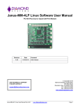
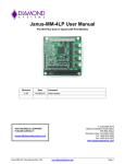
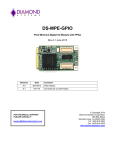
DS-MPE-CAN2L
PCIe MiniCard Dual CAN 2.0 Port Module
Rev A.0 April 2014
Revision
Date
A.0
4/25/2014
FOR TECHNICAL SUPPORT
PLEASE CONTACT:
[email protected]
Comment
Initial release
Copyright 2014
Diamond Systems Corporation
555 Ellis Street
Mountain View, CA 94043 USA
Tel 1-650-810-2500
Fax 1-650-810-2525
www.diamondsystems.com
CONTENTS
1.
2.
Important Safe Handling Information .............................................................................................................3
Introduction .......................................................................................................................................................4
2.1 Description .....................................................................................................................................................4
2.2 Features .........................................................................................................................................................4
2.3 Operating System Support ............................................................................................................................4
2.4 Mechanical, Electrical, Environmental ...........................................................................................................4
3. Packing List .......................................................................................................................................................4
4. Functional Overview .........................................................................................................................................5
4.1 Functional Block Diagram ..............................................................................................................................5
4.2 Mechanical Board Drawing ............................................................................................................................6
4.3 CAN Controllers .............................................................................................................................................6
4.4 Transceivers ..................................................................................................................................................7
4.5 Isolation .........................................................................................................................................................7
4.6 Power Supply.................................................................................................................................................7
5. Installation .........................................................................................................................................................7
6. Connector Pinout and Pin Description ...........................................................................................................8
6.1 PCIe MiniCard Edge Connector (J1) .............................................................................................................8
6.2 CAN Ports (J4, J7) .........................................................................................................................................8
7. Jumper Configuration ......................................................................................................................................9
8. Driver installation..............................................................................................................................................9
8.1 Installing the Software ...................................................................................................................................9
8.2 Setting the Baud Rate ................................................................................................................................ 10
8.3 Setting the CAN ID and Message Length .................................................................................................. 11
8.4 Writing a Message ...................................................................................................................................... 12
8.5 Viewing Messages ...................................................................................................................................... 13
9. How to configure and manage the ports using software .......................................................................... 15
9.1 API to Configure and Manage CAN ports. ................................................................................................. 15
10. Specifications................................................................................................................................................. 19
DS-MPE-CAN2L User Manual Rev A.
www.diamondsystems.com
Page 2
1. IMPORTANT SAFE HANDLING INFORMATION
WARNING!
ESD-Sensitive Electronic Equipment
Observe ESD-safe handling procedures when working with this product.
Always use this product in a properly grounded work area and wear appropriate
ESD-preventive clothing and/or accessories.
Always store this product in ESD-protective packaging when not in use.
Safe Handling Precautions
This board contains a high density connector with many connections to sensitive electronic components. This
creates many opportunities for accidental damage during handling, installation and connection to other
equipment. The list here describes common causes of failure found on boards returned to Diamond Systems for
repair. This information is provided as a source of advice to help you prevent damaging your Diamond (or any
vendor’s) embedded computer boards.
ESD damage – This type of damage is usually almost impossible to detect, because there is no visual sign of
failure or damage. The symptom is that the board eventually simply stops working, because some component
becomes defective. Usually the failure can be identified and the chip can be replaced. To prevent ESD damage,
always follow proper ESD-prevention practices when handling computer boards.
Damage during handling or storage – On some boards we have noticed physical damage from mishandling. A
common observation is that a screwdriver slipped while installing the board, causing a gouge in the PCB surface
and cutting signal traces or damaging components.
Another common observation is damaged board corners, indicating the board was dropped. This may or may not
cause damage to the circuitry, depending on what is near the corner. Most of our boards are designed with at
least 25 mils clearance between the board edge and any component pad, and ground / power planes are at least
20 mils from the edge to avoid possible shorting from this type of damage. However these design rules are not
sufficient to prevent damage in all situations.
A third cause of failure is when a metal screwdriver tip slips, or a screw drops onto the board while it is powered
on, causing a short between a power pin and a signal pin on a component. This can cause overvoltage / power
supply problems described below. To avoid this type of failure, only perform assembly operations when the
system is powered off.
Sometimes boards are stored in racks with slots that grip the edge of the board. This is a common practice for
board manufacturers. However our boards are generally very dense, and if the board has components very close
to the board edge, they can be damaged or even knocked off the board when the board tilts back in the rack.
Diamond recommends that all our boards be stored only in individual ESD-safe packaging. If multiple boards are
stored together, they should be contained in bins with dividers between boards. Do not pile boards on top of each
other or cram too many boards into a small location. This can cause damage to connector pins or fragile
components.
Power supply wired backwards – Our power supplies and boards are not designed to withstand a reverse
power supply connection. This will destroy each IC that is connected to the power supply (i.e. almost all ICs). In
this case the board will most likely will be unrepairable and must be replaced. A chip destroyed by reverse power
or by excessive power will often have a visible hole on the top or show some deformation on the top surface due
to vaporization inside the package. Check twice before applying power!
Overvoltage on digital I/O line – If a digital I/O signal is connected to a voltage above the maximum specified
voltage, the digital circuitry can be damaged. On most of our boards the acceptable range of voltages connected
to digital I/O signals is 0-5V, and they can withstand about 0.5V beyond that (-0.5 to 5.5V) before being damaged.
However logic signals at 12V and even 24V are common, and if one of these is connected to a 5V logic chip, the
chip will be damaged, and the damage could even extend past that chip to others in the circuit
DS-MPE-CAN2L User Manual Rev A.
www.diamondsystems.com
Page 3
2. INTRODUCTION
2.1
Description
DS-MPE-CAN2L implements a CAN protocol bus controller that performs serial communications according to the
CAN 2.0A and CAN 2.0B specifications. The protocol uses a multi-master bus configuration for the transfer of
frames between nodes of the network and manages error handling with no burden on the host processor.
2.2
Features
2 CAN 2.0B ports with a 1Mbps data rate and programmable interrupts
31 receive buffers for improved performance
1 high priority transmit buffer and 16 standard priority transmit buffers
16 programmable acceptance filters
11-bit and 29-bit identifiers
500V port-to-port and input-to-output isolation
Driver supports dual-independent and dual-redundant modes
Latching connectors for increased ruggedness
2.3
Operating System Support
Linux 2.6.16, 2.6.27, 2.6.31 and 2.6.32
Windows 7, XP
2.4
Mechanical, Electrical, Environmental
PCIe MiniCard full size format
Dimensions: 50.95mm x 30mm (2” x 1.18”)
-40°C to +85°C ambient operating temperature
Power input requirements: +3.3VDC +/- 5%
3. PACKING LIST
The DS-MPE-CAN2L product comes with the PCIe MiniCard hardware assembly,
a cable kit with two dual serial cables, and a hardware kit containing jumpers
and mounting screws.
Quantity
Part Number
Description
1
9150500
DS-MPE-CAN2L hardware assembly
1
6800500
Hardware Kit with jumpers and screws
2
6981182
CANbus 2.0 cables
DS-MPE-CAN2L User Manual Rev A.
www.diamondsystems.com
Page 4
4. FUNCTIONAL OVERVIEW
4.1
Functional Block Diagram
The DS-MPE-CAN2L block diagram is shown below.
DS-MPE-CAN2L User Manual Rev A.
www.diamondsystems.com
Page 5
4.2
Mechanical Board Drawing
The DS-MPE-CAN2L conforms to the PCIe MiniCard electromechanical specification revision 1.2, full size format.
Overall dimensions are 50.95mm L x 30.00mm W.
The two mounting holes are isolated from the CPU ground and not connected to any ground lines.
4.3 CAN Controllers
The module offers two CAN controllers implemented as FPGA cores inside a Xilinx Spartan 6 FPGA. The core
provides the following key features:
Conforms to the ISO 11898 -1, CAN 2.0A, and CAN 2.0B standards
Supports both standard (11-bit identifier) and extended (29-bit identifier) frames
Supports bit rates up to 1Mbps
Transmit message FIFO with a user-configurable depth of up to 64 messages
Transmit prioritization through one High-Priority Transmit buffer
Automatic re-transmission on errors or arbitration loss
Receive message FIFO with a user-configurable depth of up to 64 messages
Acceptance filtering with a user-configurable number of up to 16 acceptance filters
Sleep Mode with automatic wake-up
Loop Back Mode for diagnostic applications
Maskable Error and Status Interrupts
Readable Error Counters
DS-MPE-CAN2L User Manual Rev A.
www.diamondsystems.com
Page 6
4.4 Transceivers
The transceivers are Analog Devices ADM3053 combination isolation and transceiver. It provides isolated +5V to
power the isolated side of the transceiver. This isolated +5V is available on the I/O connector.
4.5 Isolation
The module supports 500V isolation between each CAN port and the host, and between each CAN port and the
other, via the ADM3053 isolated transceiver. An optional high-voltage resistor can be installed across each
isolation barrier to enable leakage current flow between the isolated transceiver grounds and the host ground.
4.6 Power Supply
The module is powered by +3.3V from the PCIe MiniCard socket. It provides all other required voltages on board,
including +5V for the CAN transceivers and the FPGA core voltages.
5. INSTALLATION
The DS-MPE-CAN2L plugs in to any socket meeting the PCIe MiniCard specifications. It has two connectors,
one for each pair of serial ports, a protocol configuration jumper block, and a pair of mounting holes. To install the
DS-MPE-CAN2L, fully insert the board into a PCIe MiniCard connector and secure in place by inserting one screw
from the hardware kit into each of the mounting holes, see the diagram below.
Mounting holes
J4 CAN connector
J7 CAN connector
J3 termination jumper block
J6 termination jumper block
J1 PCIe MiniCard edge finger connector
DS-MPE-CAN2L User Manual Rev A.
www.diamondsystems.com
Page 7
6. CONNECTOR PINOUT AND PIN DESCRIPTION
6.1
PCIe MiniCard Edge Connector (J1)
The DS-MPE-CAN2L module is compatible with the standard Mini PCIe socket pinout as shown below.
WAKE#
COEX1
COEX2
CLKREQ#
GND1
REFCLKREFCLK+
GND2
RSVD(UIM_C8)
RSVD(UIM_C4)
GND3
PERN0
PERP0
GND4
GND5
PETN0
PETP0
GND6
GND7
+3.3VAUX_1
+3.3VAUX_2
GND8
RSVD1
RSVD2
RSVD3
RSVD4
6.2
1
2
3
4
5
6
7
8
9
10
11
12
13
14
15
16
KEY
17
18
19
20
21
22
23
24
25
26
27
28
29
30
31
32
33
34
35
36
37
38
39
40
41
42
43
44
45
46
47
48
49
50
51
52
+3.3VAUX_3
GND9
+1.5V_1
UIM_PWR
UIM_DATA
UIM_CLK
UIM_RESET
UIM_VPP
GND10
W_DISABLE#
PERST#
+3.3VAUX_4
GND11
+1.5V_2
SMB_CLK
SMB_DATA
GND12
USB_DUSB_D+
GND13
LED_WWAN#
LED_WLAN#
LED_WPAN#
+1.5V_3
GND14
+3.3VAUX_5
CAN Ports (J4, J7)
Each of the two CAN ports has its own 4-pin latching connector with the following pin out.
1
2
3
4
Ground Iso
CAN L
CAN H
Ground Iso
Connector Part Number / Description
BM04B-GHS-TBT
4 pos, 1.25mm, vertical, latching, SMD
DS-MPE-CAN2L User Manual Rev A.
www.diamondsystems.com
Page 8
7. JUMPER CONFIGURATION
The DS-MPE-CAN2L module has two line termination jumper blocks, one for each port. Jumper block J3 is for
port J4, and jumper block J6 is for port J7. Jumper blocks J3 and J6 are identical. The default is no jumpers
installed. To add termination for a port’s bias line, CAN-H line, or CAN-L line, add a jumper at B, H or L location
respectively.
B
H
L
O
O
O
O
O
O
8. DRIVER INSTALLATION
8.1
Installing the Software
The following steps are used to install the CAN interface utility software.
Step-1:
Unzip the PCI_CAN_Interface.zip file on the enclosed CD using the below commands.
Unzip PCI_CAN_Interface.zip
A pci_can directory will be created where the zip file is extracted. The pci_can directory contains the following
files.
ls –l
1.
2.
3.
4.
CANLib : CAN Library
pci_fpga.ko : PCI CAN Interface driver
CAN_Monitor : PCI CAN CAN_Monitor utility.
qt-opensource-linux-x86-5.2.1.run : Qt Installer which is required by the PCI CAN Interface utility.
Step-2:
Install the Qt shared libraries using the Qt Installer. Execute the command below and follow the Qt Installer
instructions. Use the command below to install the Qt shared libraries. Install Qt at the default locations.
cd pci_can
./qt-opensource-linux-x86-5.2.1.run
Note: The Qt shared libraries should be installed only once.
Step-3:
Load the PCI CAN interface driver using the command below from the pcifpga_driver directory where the zip file
is extracted.
cd pcifpga_driver
insmod pci_fpga.ko
Step-4:
PCI CAN Utility is based on the CANLib library. Linux expects the Library path to be exported before using it. Use
the below command to export the Library path before starting the PCI CAN utility in Step-5.
DS-MPE-CAN2L User Manual Rev A.
www.diamondsystems.com
Page 9
export LD_LIBRARY_PATH=$ LD_LIBRARY_PATH:/path-to-CANLib
Step-5:
Start the PCI CAN Utility using the command below from the CAN_Monitor directory where the zip file is
extracted.
cd CAN_monitor
./CAN
The above command will open the CAN interface utility.
Note: To start CAN utility in the future, follow Steps 3 to 5 only.
8.2
Setting the Baud Rate
Using the CAN interface utility software, the baud rate for each port can be selected. On the desired CAN port,
select the baud rate from the Baud Rate drop-down menu. After selecting the desired baud rate, press “Connect”
to connect with specified baud rate as shown in below figure.
To change the baud rate, click on “Disconnect” and select a new baud rate.
DS-MPE-CAN2L User Manual Rev A.
www.diamondsystems.com
Page 10
8.3
Setting the CAN ID and Message Length
Set the CAN ID and CAN message length for each CAN port by entering the desired numbers into the ID and Len
fields respectively for that port.
DS-MPE-CAN2L User Manual Rev A.
www.diamondsystems.com
Page 11
8.4
Writing a Message
To write a message on a CAN port, define the CAN message by entering the desired data into the Data (Hex)
fields. Then click on “Write Message” as shown in the below figure.
To transmit to a different CAN ID, change the data in the CAN ID field, enter the desired data into the Data (Hex)
fields, and click on “Write Message”.
To change the message length, change the CAN message length to the new length, enter the desired data into
the Data (Hex) fields, and click on “Write Message”.
To transmit a different CAN message to the same CAN ID, change the CAN message to the desired data, and
click on “Write Message”.
DS-MPE-CAN2L User Manual Rev A.
www.diamondsystems.com
Page 12
8.5
Viewing Messages
Transmitted messages are listed in the CAN message box for the sending CAN port as shown in below figure.
DS-MPE-CAN2L User Manual Rev A.
www.diamondsystems.com
Page 13
Received CAN messages are listed in the CAN message box for the CAN port receiving the message as shown
in below figure.
DS-MPE-CAN2L User Manual Rev A.
www.diamondsystems.com
Page 14
9. HOW TO CONFIGURE AND MANAGE THE PORTS USING SOFTWARE
CANLib library provides the set of APIs to configure and manage the CAN ports. The CANLib library can be used
to build the CAN application. It is a shared library built on top of Linux platform. To compile the CANLib shared
library, use the below command
cd CANLib
make
All the CAN APIs prototypes are defined in the can.h file. This file is located in the CANLib directory. Include the
can.h file in the application to use all these APIs.
9.1
API to Configure and Manage CAN ports.
init_can0() & init_can1(): These function will initialize the CAN#0 & CAN#1 ports respectively.
Both these functions will return the CAN file descriptor (fd). The return value of these functions should be
retained for all subsequent operations. Its prototypes are defined in the can.h file. Declare two CAN file
descriptors and retains its return values.
#include “can.h”
…
int can0_fd;
int can1_fd;
…
can0_fd = init_can0() ;
if ( can0_fd < 0 )
{
printf("Error while initializing the CAN#0\n") ;
exit(0) ;
}
…
can1_fd = init_can1() ;
if ( can1_fd < 0 )
{
printf("Error while initializing the CAN#1\n") ;
exit(0) ;
}
Baud rate configuration.
set_baudrate() : This function will configure the baud rate for the specified CAN port. By default it will not
configure any baud rate.
DS-MPE-CAN2L User Manual Rev A.
www.diamondsystems.com
Page 15
// Set 500k Baud rate for CAN#0
ret_val = set_baudrate(can0_fd, CAN_SPEED_500K ) ;
if ( ret_val < 0 )
{
printf("Error while setting the baud rate \n") ;
exit(0) ;
}
// Set 500k Baud rate for CAN#1
ret_val = set_baudrate(can1_fd, CAN_SPEED_500K ) ;
if ( ret_val < 0 )
{
printf("Error while setting the baud rate \n") ;
exit(0) ;
}
Use below macros for setting the different baud rates. These macros can also be found in can.h file.
CAN_SPEED_1M
CAN_SPEED_800K
CAN_SPEED_500K
CAN_SPEED_250K
CAN_SPEED_125K
CAN_SPEED_100K
CAN_SPEED_50K
CAN_SPEED_20K
CAN Transmit & Receive:
can_tx() & can_rx() : These function will be used to Transmit and Receive the CAN messages respectively.
CAN Transmit Prototype.
int can_tx( int can_fd, unsigned char msgType, unsigned int can_id, int len,unsigned char *data) ;
Assign the appropriate values, before calling the can_tx function.
can0_fd : CAN descriptor, return value from init_can0() function
msgType = MSG_STANDARD ; // or MSG_EXTENDED .
can_id = 0x12 ; // CAN ID, if the msgType is MSG_STANDARD then it should be 11-Bit CAN Message ID
// if the msgType is MSG_EXTENDED then it should be 29-Bit CAN Message ID
len = 4 ; // CAN Transmit Data Length
data : CAN message data.
data[0] = 0x1A ;
data[1] = 0xAB ;
DS-MPE-CAN2L User Manual Rev A.
www.diamondsystems.com
Page 16
data[2] = 0x22 ;
data[3] = 0x4D ;
ret_val = can_tx(can0_fd, msgType, can_id, dlc, data) ;
if ( ret_val < 0 )
{
printf("Error while transmitting the CAN message.\n") ;
close(can1_fd) ;
exit(0) ;
}
The above sample code will transmit the CAN Standard message with CAN ID=0x12 of data length=4 and
message data = {0x1A, 0xAB, 0x22, 0x4D};
CAN Receive Prototype.
int can_rx(int can_fd, unsigned char *msgType, unsigned char *rx_data, unsigned int *can_id, unsigned char
*can_msg_len) ;
Pass the appropriate pointers for calling the can_rx function.
if ( can_rx(can0_fd, &msgType, data, &can_id, &dlc) )
{
If (msgType == MSG_STANDARD)
{
// received message is CAN Standard Message.
}
else if (msgType == MSG_EXTENDED)
{
// received message is CAN Extended Message.
}
// dlc : Received CAN Data Length
// can_id : Will contain the CAN Message ID
// Data of dlc length
printf("ID=%x DLC=%d Data : ", can_id, dlc) ;
for (i=0; i< dlc; i++ )
printf("%x ", data[i] ) ;
printf("\n") ;
}
The sample example programs for both transmit and receive can be found in the CANLib directory for the
reference.
DS-MPE-CAN2L User Manual Rev A.
www.diamondsystems.com
Page 17
Compiling CAN Application using CANLib Library
Export the Library path using below command.
export LD_LIBRARY_PATH=$ LD_LIBRARY_PATH:/path-to-CANLib
To compile the application, use the below command.
g++ can_app.c -lCAN –L/path-to-CANLib -o can_app
DS-MPE-CAN2L User Manual Rev A.
www.diamondsystems.com
Page 18
10. SPECIFICATIONS
Number of ports
2 CAN 2.0B
Data rate
1Mbps
Number of receive buffers
31
Number of transmit buffers
1 high priority
16 standard priority
Acceptance filters
16 programmable, 29-bit
Identifiers
11-bit and 29-bit
Modes
Dual-independent
Dual-redundant
Isolation
500V port-to-port and input-to-output
Input power
+3.3VDC +/-5%
Power consumption
0.462W @ 3.3V
Software drivers
Windows XP
Linux 2.6.16, 2.6.27, 2.6.31, and 2.6.32
Operating temperature
-40°C to +85°C
MTBF
1,583,210 hours at 20°C
Dimensions
50.95mm x 30mm (2” x 1.18”)
Weight
8.5g (0.3oz)
RoHS Compliant
Yes
DS-MPE-CAN2L User Manual Rev A.
www.diamondsystems.com
Page 19