1
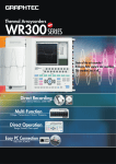
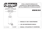
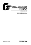
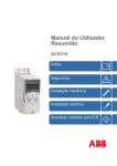
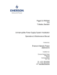
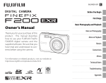
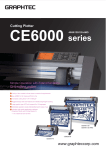
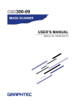
WR8500 SERIES
Thermal Arraycorders
Easy Operation and High-level Performance
The WR8500 series thermal arraycorders are economical, no-frills waveform recorders which feature a
large-format LCD screen for waveform monitoring, and
a performance level usually found in our more expensive
recorders such as the WR9000. Chart speeds up to 200
mm/s are selectable from the front panel, and the sampling rate is a high-speed 4 µs. For users who need
increased functionality, we offer a wide range of options
such as logic amp input, floppy and MO disk drives,
RS-232C and GPIB interfaces, additional memory, DC
drive, and a Z-fold chart paper box.
User-friendly functions—make the WR8500 so much easier to use
• External sampling function captures data synchronized to an
external signal into memory
• Wide range of trigger and remote control functions, as well as an
event marker function to record phenomena as they occur
• Selection of noise filters: OFF, 1.5 Hz (line), 10, 30, 50, 100, 500
Hz, 5 kHz
• Up to 8 hours memory backup
WR8500 16-channel model
Easy operation—just like an analog recorder
Independent setup parameter keys for each channel means that you
can change parameters for any channel even during recording. Up to
four sets of setup parameters can be saved in memory. A separate
bank of chart speed setting keys enables you to change the chart speed
at any time, and four directional cursor keys are provided for easy
menu selection.
Three recording modes for diverse measurement scenarios
The WR8500 comes standard with three recording modes to suit your
applications: Recorder, Memory Recorder, and Logging. In Recorder
mode, the WR8500 displays and records analog signals as realtime
waveforms, and it can also capture data into memory simultaneously.
Voltage ranges are from 50 mV to 500 V, and logic input is available
as an option. In Memory Recorder mode, data captured into memory
can be displayed and recorded as waveforms. The WR8500 comes
with a standard memory capacity of 64 kwords/channel, and an
additional 256 kwords/channel memory is available as an option. In
Logging mode, measured data is displayed and recorded as digital
values. Data can be captured directly onto a floppy or MO disk*1.
Direct key operation for an analog look and feel
Wide-format recording and display
Graphtec's 8 dot/mm thermal array technology enables the information
shown on the LCD panel to be accurately reproduced on chart paper.
In addition to waveform recording up to 200 mm wide and printing of
digital values, you can also print out a list of setup parameters, as well
as a hard copy of the display screen. 11 formats are available for the 8channel model in Y-T mode*2, and a 150 x 150 mm format in the X-Y
mode. A selection of 9 grid patterns is also offered.
Separate bank of chart speed setting keys
File Conversion Software
Graphtec's OPS011 file conversion software (Windows version)
converts data stored on the WR8500's floppy or MO disks into TXT or
CSV formats so that it can be used with spreadsheet applications such
as Microsoft's Excel or Lotus 1-2-3.
*1 Floppy disk and MO drives are available as options.
*2 13 formats for the 16-ch model
Functions to Make the Most of Your Measurement Data
Cursor Functions
Range/Span Setting Functions
Overwrite
For data captured in memory, you can use a
cursor to read measured data at a specific
position on the waveform. The jog/shuttle
dial moves the cursor with speed and ease.
• Scrolling function
The jog/shuttle dial is used to scroll the
display of data captured in memory
• Cursor Readout function
Displays the electric potential, time and
frequency (difference) at the cursor position
in waveform display
• Statistical Calculation functions
Perform statistical calculations on the data
in the range specified by the waveform
cursors
• Storage of data in the cursor-specified range
Saves data in the range specified by the
waveform cursors to a floppy or MO*1 disk
• Cursor Zoom function
Provides an enlarged display of data in the
range specified by the waveform cursors
• Print function
Prints out data in the range specified by
waveform cursors
For voltage measurement, three functions for
setting the range and span are provided:
• Auto Range
Automatically sets the optimum measurement range for measuring voltage
• Span mode
Specifying the upper and lower limit values
for a measurement range that has already
been specified determines the zero position
• Position mode
Specifying the zero position for a measurement range that has already been specified
determines the upper and lower limit
values.
When this function is enabled, new waveforms will be displayed over the waveform
already being displayed so that you can make
comparisons.
Vernier
The VERNI function enables fine adjustment
of the measurement range.
• Example of recording a 13.5 V input signal (internal reference)
Remote Interface
A remote interface (CMOS level) which
enables start/stop control of the recorder
using external signals is built in.
Calculation Functions
The WR8500 can perform the following 7
cursor-specified statistical calculations:
• Standard Deviation (S.D.)
• Maximum and Minimum Values (Max/
Min)
• Absolute Peak-to-Peak Values (p-p)
• Averaging (Average)
• Root-Mean-Square (R.M.S.)
• Rise Time and Fall Time
• X-Y Area and Y-T Area
Grid Patterns
Auto Zero
10 V range
20 V range
10 V range to 15 V range
The Auto Zero function is used to comVernier ratio: approx. 100%
Vernier ratio: approx. 100%
Vernier ratio: approx. 67%
pulsorily move the reference potential of the
signal input to the WR8500’s zero-point
Scaling
position which is regarded as the 0 V position for recording. The voltage at the time the This function enables you to convert voltage
signals to another industrial unit, and to
Auto Zero function is enabled becomes the
specify upper and lower limits of scaling and
reference potential.
a user-defined unit for the results of conAuto Zero
On
version. The user-defined unit (mm, kg, etc.)
can be specified using up to 6 characters.
In recorder mode and memory recorder
mode, a choice of 9 grid patterns is provided
to enable easier reading of the waveform.
10 mm fine
10 mm coarse
10 div fine
5 mm fine
5 mm coarse
10 div coarse
4 mm fine
4 mm coarse
NONE
0V
–V1
*1 Floppy disk and MO drives are available as
options.
–V1 is recorded as the reference potential (0 V)
Options
Logic amp
Floppy disk drive
Standard Accessories
B-375
B-371
16 channels/unit
3.5", 1.44 MB
Magneto-optic disk drive B-364
RS-232C interface
B-372
3.5", 640 MB
GP-IB interface
Additional memory
B-363
B-373
Conforms to IEEE-488-1978
256 kwords/ch, for 8-ch model
DC drive
B-374
B-376
256 kwords/ch, for 16-ch model
10 to 16 VDC, for 8-ch model
B-377
Long-length Z-fold paper box B-367
WR8500 Interface
Command Manual
Chart paper
1 roll
Cannot be installed
concurrently
Chart paper flanges
Power cable
1 set
1
Cannot be installed
concurrently
Remote connector
User's manual
1
1
10 to 16 VDC, for 16-ch model
For use with PZ231A 100-m length Z-fold paper
WR8500- RS-232C and GP-IB Control Commands
UM-351
Specifications
Basic Specifications
Measurement modes
Number of channels
Memory capacity
Display panel
Recording method
Chart paper
Recorded width
Isolation voltage
Isolation resistance
Backup functions
Interface
Operating range
Power rating
Power consumption
External dimensions
Weight
Recorder, Memory Recorder, and Logging
8, 16
64 kwords/channel (optionally expandable to 256 kwords/channel)
8.9” LCD
Thermal recording by a thermal array print head of 8-dot/mm pitch
Roll paper (part no. PR231A), 210 mm × 40 m, trace color: black
205 mm (1,640 dots) maximum
1 min at 1,500 VAC between the AC power supply and frame
20 MΩ or more at 500 VDC between the AC power supply and frame, and
between the input terminals and frame
Settings: EEPROM; clock*1: secondary lithium battery (when fully charged, lasts
about three months if the RAM Backup function is Off); RAM Backup*1:
secondary lithium battery, when fully charged lasts four hours minimum (with
the memory option) or eight hours minimum (with standard memory only)
Option, RS-232C or GP-IB
0 to 40°C, 30 to 80% RH (5 to 35°C for printing)
100 V series: 100 to 120 V
100 V/200 V series: 100 to 120 V/200 to 240 V
CE mark: 100 to 120/200 to 240 V
DC drive available as an option
8-ch model: 360 VA max., 16-ch model: 400 VA max. (with the 100-120 VAC
system)
8-ch model: approx. 360 (W) × 296 (D) × 120 (H) mm,
16-ch model: approx. 360 (W) × 296 (D) × 200 (H) mm, excluding rubber feet
and protuberances
8-ch model: approx. 6.5 kg (approx. 8.0 kg with the DC drive option); 16-ch
model: approx. 10 kg (approx. 10.5 kg with the DC drive option)
MEMORY functions
4 µs to 5 s (in steps of 1, 2, 4, 5, and 8), External
[4 µs to 100 ms (in steps of 1, 2, 4, 5, and 8) in Recorder mode]
Memory banks
1, 2, 4, 8, 16, 32, or 64 blocks
Memory coupling (Expand) 8 ch × 1, 4 ch × 2, 2 ch × 4, or 1 ch × 8
Specifiable output zone 10 to 100% (10% steps)
Waveform scaling
Time axis: ×8 to ×1/8 plus Fixed (A4 size); between cursors; voltage axis (data
specified by cursors)
Cursor functions
Cursor readout, scrolling, zoom
Sampling speeds
TRIGGER functions
Trigger modes
*1
*2
*3
*4
Off, Manual, External, and Internal (Only, Combination, All OR, All AND,
Logic OR*2 Logic AND*2, Window In, Window Out )
The secondary lithium battery is shared.
Requires installation of the logic amp option.
In Recorder or Logging mode only (fixed to Memory in Memory Recorder mode).
In X-Y display mode, the frequency response varies with the number of measurement channels
(1 ch: 800 Hz, 2 ch: 400 Hz, 4 ch: 200 Hz, 8 ch: 100 Hz)
Channel combinations
Trigger slope
Trigger level
Trigger functions*3
Trigger delay
Trigger action
RECORDER mode
Waveform display
Display format: Y-T, X-Y
Display direction: Horizontal scrolling (specify for Y-T)
Channels displayed: Y-T=Same as Recording formats
X-Y=1 X-axis channel, 7 Y-axis channels*4
200 mm × 1, 100 mm × 1, 80 mm × 2, 50 mm × 4, 25 mm × 8, 160 mm × 1, 100
mm × 2, 50 mm × 2, 40 mm × 4, 20 mm × 8, (12.5 mm × 16, 10 mm × 16), User
Figures in ( ) apply to the 16-ch model only
1, 1.25, 2, 2.5, 5, 10, 12.5, 20, 25, 50, 100*, 200* mm/s, mm/min, mm/h; External
(0.03125 mm/pulse, 640 pps max)
* 100 and 200 can only be combined with “mm/s”
Recording formats
Chart speeds
MEMORY RECORDER mode
Waveform display
Measured data display
Display method
Display format: Y-T or X-Y display
Display direction: Horizontal scroll (Y-T)
Channels displayed: Y-T=Same as Recording formats
X-Y=1 X-axis channel, max. 7 Y-axis channels
Measured data of 8 (16) channels can be displayed at the left of the screen as
digital values
Figures in ( ) apply to the 16-ch model only
Roll mode display with Overwrite*5 function (overwrites specified data in
memory)
LOGGING mode
Measured data display
Display speed
Measurement interval
Recording formats
Recording interval
Memory recording
Data transfer
*5
*6
*7
*8
*9
V (Voltage input) type amp
Input configuration
Input resistance
Measurement range
Accuracy (Voltage)
Temperature coefficient
Input coupling
Maximum permissible input
voltage*1
Insulation resistance
Isolation voltage (between
the input terminal and frame)
Permissible signal
source resistance
Input bias current
CMRR
A/D conversion
Frequency response
Filter
GAIN vernier
Auto Range function
AUTO ZERO function
Input terminals
Combination of any 2 channels (AND, OR)
Rising or Falling
0 to 100% (1% steps) or directly set as a voltage level within the specified
RANGE (±F.S.)
Start, Stop, Start & Stop, Trig Memory, Trig & Trig, Trig Zoom (Recorder mode
only)
–100 to +100% (10% steps) during memory recording
Single or Repeat
Floating ground with unbalanced-load input
Approx. 1 MΩ±1%
Voltage: 50, 100, 200, 500 mV/FS 1, 2, 5, 10, 20, 50, 100, 200, 500 V/FS
±0.25% of FS
Zero point: 0.02% of FS/°C, Gain: 0.01% of FS/°C
DC, GND, CAL (1/2 FS), OFF
500 VDC* (DC + ACp-p) between + and – terminals * 30 VDC at the 50 mV to 2 V ranges
250 VACrms between terminal and frame
20 MΩ or more at 500 VDC
1 minute at 500 VAC; CE Mark compliant models: 1 minute at 2300 VAC
Measured data of any channel can be displayed as digital values using a screen
split into 1, 2, 4, 8, or (16) parts
Figures in ( ) apply to the 16-ch model only
00:00:01 to 24:00:00 (1 s steps)
*8
1 ms to 800 ms (in steps of 1, 2, 4, 5, or 8), 00:00:01 to 24:00:00 (1 s steps)
Day/month/year (at start of measurement), hh:mm:ss,
Channel-specific measured data (16 max.*9), minimum, maximum, and mean
values are recorded as digital values (after recording has been completed)
Synchronized with the display interval (7 mm/line)
Data being measured can be directly written to an external memory device
(optional floppy or MO disk)*6
Output of ASCII data via the RS-232C interface*7
Valid only when the output factor is Fixed
Both drives are options; must be specified at time of ordering
Option. The GP-IB interface cannot be used to send ASCII data in Logging mode
1 ms speed applies only when saving data to an FD or MO disk; it cannot be displayed or recorded
For a 16-ch model, data is displayed in two rows
LO (Logic input) type amp, 16 channels/unit
Number of channels
Input voltage range
Sampling speed
Threshold levels
Trigger settings
Trigger filter
Display/recording
Zone positioning
1 kΩ maximum
Standard accessories
10nA (typical)
100 dB (50/60 Hz, signal source resistance up to 500 Ω)
Sampling speed: 4 µs max, Resolution: 12 bits (10 bits*2)
DC coupling: DC to 50 kHz (+1/–3 dB typical)
Line: 1.5 Hz ((–3 dB) at –6 dB/oct), Lowpass: 10, 30, 50, 100, 500, 5k Hz ((–3 dB) at –6 dB/oct)
Variable setting of the measurement range from 120 to 40% (digital specification)
Automatically selects the measurement range best suited to the input
Automatically sets the zero point to the reference potential of the voltage input
Safety sockets (2 terminals: +, –)
16 (4 per terminal × 4)
0 to +25 V max (Single-ended ground)
Synchronized with the recorder
TTL (+1.4 V)
CMOS (+2.5 V)
Contact point (+5 V)
AND or OR trigger for 16 channels (when the condition of
an armed trigger is met)
Sampling speed × 2n (n = 0 to 6)
Can be switched on/off for each group of four channels
Each four-channel group (A, B, C, D) can be assigned to a
zone for display and recording
Four RIC-10 probe sets
*1 The maximum input voltage that can be measured (including peak values) is within
the RANGE voltage ± full scale.
*2 Resolution of measured data during internal processing by the amp.
To ensure correct and safe use of your recorder:
• Read your User's Manual before using the recorder, and operate it correctly in accordance with the procedures described.
• To prevent malfunctions or electrical shock due to current leakage, ensure that the recorder has a good protective ground, and that the supply voltage conforms to the recorder's power rating.
Brand names and product names listed in this brochure are the trademarks or registered trademarks of their respective owners.
Specifications are subject to change without notice.
503-10 Shinano-cho, Totsuka-ku,
Yokohama 244-8503, Japan
Tel : +81(045) 825-6250
Fax : +81(045) 825-6396
Email : [email protected]
Web : www.graphteccorp.com
RWR85001000205SU Printed in Japan