1
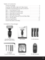
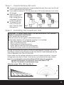
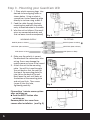
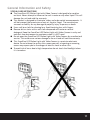
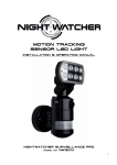
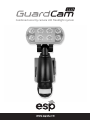
Combined security camera LED floodlight system
IMPORTANT NOTE - PLEASE READ
Installation of back up batteries is vital to the correct recording operation
of GuardCam LED. Under normal operation GuardCam LED requires very
little user intervention. The unit will make time and date stamped
recordings directly to the installed SD card, when the SD card is full
GuardCam LED will overwrite the oldest recording therefore maintaining
a constant history of recordings. To ensure continuation of this operation
the time and date settings must not be lost. Please make sure back up
batteries are fitted correctly upon installation and replaced within 24
hours should the low battery indicator (a red flashing light behind the
lens of the PIR detector) be seen.
2
Table of contents
Contents of package . . . . . . . . . . . . . . . . . . . . . . . . . . . . . . . . . . . . . . . . . . . . . . . . 3
GuardCam LED Motion Light with Video Camera . . . . . . . . . . . . . . . . . . . . . . . 4
Installation and replacement of back up batteries . . . . . . . . . . . . . . . . . . . . . 4
Step 1 - Insert/remove SD Card . . . . . . . . . . . . . . . . . . . . . . . . . . . . . . . . . . . . . . 5
Step 2 - Installing the GuardCam LED . . . . . . . . . . . . . . . . . . . . . . . . . . . . . . . . . 5
Step 3 - Mounting the GuardCam LED . . . . . . . . . . . . . . . . . . . . . . . . . . . . . . . . 6
Step 4 - Adjusting the settings . . . . . . . . . . . . . . . . . . . . . . . . . . . . . . . . . . . . . . 7
Step 5 - Setting the Date and Time and Video Mode . . . . . . . . . . . . . . . . . . . 9
Step 6 - Viewing Video . . . . . . . . . . . . . . . . . . . . . . . . . . . . . . . . . . . . . . . . . . . . 10
Technical Specifications . . . . . . . . . . . . . . . . . . . . . . . . . . . . . . . . . . . . . . . . . . . 10
General Information and Safety . . . . . . . . . . . . . . . . . . . . . . . . . . . . . . . . . . . . . 11
Contents of package
GuardCam LED Motion
Light with Video Camera
1 x Allen key
2 x screws
2 x plastic masonry plugs
User Manual
3 x AAA batteries
2G SD card and
SD USB card reader
3
GuardCam LED Motion Light with Video Camera
Floodlight Cover
High intensity LED
45º
45º
50º
Waterproof cover
3 mode selection
Camera lens
PIR lens
Low battery indicator
45º
45º
35º
Installation and replacement of back up batteries
The function of the back up batteries is to provide power to the "PIR Sensor",
"Audio" and "Date/Time settings" if a mains power outage occurs and preserve
date/time settings for a minimum of 48 hours prior to mains power being restored.
Unscrew the screw A and remove back cover. Unscrew screw B and remove
battery cover.
I Put the 3pcs “AAA” 1.5V batteries into the battery compartment and make sure
the polarity (- +) is aligned correctly.
I Replace battery cover and back
cover, tightening screws carefully.
G Note: To guard against damage from
battery leakage it is good practice to
replace batteries on
a yearly basis .
G To maintain battery back up function
please replace batteries after a total
of 48 hours of mains power failure.
Low Battery Indicator
A Red LED light will start to flash from behind the PIR lens when the battery is
running out of power. In this case, please be sure to replace the battery. If the
battery is out of power, the next time there is a power cut or power fluctuation,
the system may not display the correct date and time.
4
Step 1 – Insert/remove SD card
I Unscrew the waterproofed cover using provided Allen key, then insert the SD card
until it automatically locks into place.
I If you need to remove the SD card, please press OFF button and take it out within
30 seconds.
I When LED light turns
green, meaning SD
card is being read, do
not remove SD card
or data may be lost.
I To remove SD card,
push in SD card to
eject. Once to unlock
Fig. 1
then pull out.
Step 2 - Installing the GuardCam LED
IMPORTANT - IF IN ANY DOUBT ABOUT THE INSTALLATION OF THIS PRODUCT,
CONSULT A QUALIFIED ELECTRICIAN
G This product must be earthed
G Do not mount the unit against inflammable surfaces
G The motion detector will not operate correctly if it is installed:
- Near the outlet of a central heating boiler
- Near air conditioning plant
- Pointing directly at moving vehicles
- Within sight of reflections from moving water
- Where other lamps could shine on the detector
BEFORE ATTEMPTING ANY INSTALLATION OR MAINTENANCE, ENSURE THAT THE
ELECTRICAL SUPPLY IS SWITCHED OFF AND THE CIRCUIT FUSES REMOVED OR THE
CIRCUIT BREAKER IS IN THE OFF POSITION.
Please make sure the voltage and polarity are correct before connection. Incorrect
voltage may cause electric shock. If you are not sure, please contact your retailer.
Note: It is recommend to mount GuardCam LED 2M above the ground for
optimum performance, do not mount the fixture below 1.2M.
See Fig. 3 for details of performance range.
10m
Detection range: 10M x 160° (see Fig. 2)
2m
Fig. 2
2m
4m
6m
8m
10m
5
Step 3 - Mounting your GuardCam LED
1. 1. Place plastic masonry plugs into
desired surface aligning holes as
shown below. Using an electric
screwdriver, fasten mounting plate
directly to surface using screws E.
2. Feed the cable through the back
mounting box and bush the cable
entry to avoid abrasion to the cable.
3. Wire the unit as follows: (Ensure all
wires are connected securely and
that no loose strands are exposed)
Fig. 3
INCOMING SUPPLY
TO FITTING
EARTH (Green & Yellow)
EARTH (Green & Yellow)
NEUTRAL (Blue or Black)
NEUTRAL (Blue or Black)
LIVE (Brown or Red)
LIVE (Brown or Red)
4. Make sure the polarity is correct.
Double check the connections after
wiring. Errors may damage the
motion sensor or cause a fire hazard.
5. Attach the unit to the mounting
plate. You will first need to angle
the unit back so that the catch at
the top of the mounting plate fits
into slot on the back of the unit.
Next lower the unit until holes at
the bottom of the mounting plate
and unit are flush. Then screw
(screw A) into this hole,
tightening carefully.
Fig. 4
Please allow 1 minute warm-up time
after switching on.
G Push the RESET button after
switching on.
Remove plastic lens cover from
camera after installation. (see Fig. 5)
Fig. 5
6
Step 4 - Adjusting the Settings
I Time control: Turn
the time control knob
to”+” side to increase
the illumination time
(7 minutes max.),
turn the control knob
to “-“ side to reduce
the illumination time
(30 seconds min.)
I Sensitivity control:
Adjust the detector
range of Passive
Infrared Motion
Fig. 6
Sensor (± 2M ~ 10M)
I Selecting working mode:
Mode 1: Suggested setting when out of town
Light + camera + speaker: all day detection
Daytime and nighttime: light, camera and speaker are all in operation
Mode 2: Suggested for day to day use
Light at night + camera all day + speaker in the daytime
Daytime: light is off, camera is on, speaker is on
Nighttime: light is on, camera is on, speaker is off.
Mode 3: Perfect for a place of business
Light at night + camera all day + speaker at night
Daytime: light is off, camera is on, speaker is off.
Nighttime: light is on, camera is on, speaker is on.
I Audio mode: for different sound selection
Option 1: Warning you are being recorded by a security camera
Option 2: Dog Barking
Option 3: Self recorded message 1 (max 10 sec)
Option 4: Self recorded message 2 (max 10 sec)
Optoin 5: Off
I LED indicator: for indicating the function status of the unit by different colour
LED lights.
1) Red: SD card is not inserted into the SD slot or the system is malfunctioning.
2) Green: The unit is recording or USB is inserted and connecting with the
computer
3) LED off: stand by (SD card is inserted into the slot), when off/record button is
pressed
Please note when off/record button is pressed, remove SD card within 30
seconds (now the LED will turn red after SD card is removed from the slot)
7
Fig. 7
Fig. 8
I Reset button: restore functions to default settings
1) Press RESET button once each time you turn on unit.
2) Please press this button in case of system malfunction.
I Off/Rec: Please press Off/Rec button to remove SD card. Please remove card
within 30 seconds of pressing the Off/Rec button to avoid loss of data.
I Set/Rec: record your own message (see fig. 9)
1) Press this button for 3 seconds, start recording your message after “beep”.
Push the button again to stop recording, and you will hear “beep” twice, or it
will stop itself after 10 seconds.
2) If you have recorded one message, repeat above step for message 2, it will be
arranged right after the first recorded message.
The message will automatically update to the latest one if you don’t erase the
old message.
I Play/Erase: listen and erase the message (see fig. 9)
1) If record 1 message only: push the button one time to listen to the message
just recorded, press for 3 seconds hearing beep twice to erase the message.
2) If record 2 messages: push the button one time to listen to the first message,
push again to listen to the second message. To erase the message you just
listened, press the button for 3
seconds, after twice beep, the message
is erased.
3) Erase all messages: press the button for
3 seconds, after twice beep, messages
are erased. Please note that if you just
MICROPHONE
listen to all messages, 10 seconds
pause is necessary, otherwise what you
erase is the one you just play.
4) If message 1 is erased, message 2 will
automatically become message 1. For
one more message record, it will then
Fig. 9
be set to message 2.
8
Step 5 - Set the Date and Time and Video Mode
This will allow the security video taken by GuardCam LED to display the correct
date and time it was taken.
1. Push TIME/DATE SET button (see fig. 10) for
3 seconds, The LCD screen will then flash
3 times, indicating you have entered
Time/Date setting mode.
2. “YEAR”setting: ”Y” and “08” are displayed on
the screen; push the button to set year from
“08-99”, push the button again and hold for
3 seconds to scroll through numbers quickly.
If you have not pressed the button for 3
seconds, it will automatically save the year
and go on to allow you to set the month.
Fig. 10
3. Repeat the same setting procedure for
MONTH/DATE/HOUR/MINUTE.
4. “VIDEO/PHOTO ”setting: when entering this mode, these two icons
and
“V” appear on the screen push the button to choose ”V” Video or ”P” Photo.
If you have not pushed any buttons for 3 second, “OK” will appear on the screen,
indicating it has automatically saved the current settings. The LCD screen will
shut off automatically 10 seconds later.
* On the ”P” (photo) setting, GuardCam LED will take a series of digital photographs
at a rate of 3 photos every second when the motion sensor is triggered.
1. START
3. MONTH
Setting
HOUR
Setting
VIDEO/PHOTO
Setting
2. YEAR
Setting
4. DATE
Setting
MINUTE
Setting
FINISH
9
Step 6 - Viewing Video
Viewing image by computer through USB card reader supplied (see Fig. 11)
I Open SD card housing with allen key supplied
I Press OFF/REC button and remove SD card from the slot.
I Put the SD card into the USB card reader supplied, then insert the card reader
into PC via a USB port and open Windows Media Player to view the video.
Fig. 11
Technical Specifications
Features and specification:
I PIR detection angle 160 Deg and detection range up to 10M
I Records 20 seconds image recording for image stream: 10fps at 480*640 Pixels
I Built in SD card slot for SD memory card
I SD card slot for additional storage, max memory size up to 2G
I SD card spec.: FAT
I Automatic exposure control, white balance and sharpness
I Auto Date & Time stamp
I Effective viewing angle: 60 deg
I Effective viewing distance: 8M
I Image format: JPEG AVI File
I Powered by AC 100V to 240V(subject to requirement)
I 8pcs 1W Nichia super power white LED
I Auto light sensor
I Sensitivity control
I Floodlight time delay control
10
General Information and Safety
SPECIAL CARE INSTRUCTIONS
G The GuardCam LED Motion Light with Video Camera is designed to be weather
resistant. Never attempt to immerse the unit in water or any other liquid. This will
damage the unit and void the warranty.
G This product is designed to illuminate, video, and make verbal announcements. It
will not prevent the commission of any act, legal or illegal. The manufacturer
assumes no liability for any damage to property, injury to person, or death.
G Use a soft lens cloth for cleaning lens. Avoid touching lens with fingers.
G Remove dirt or stains with a soft cloth dampened with water or neutral
detergent. Keep the GuardCam LED Motion Light with Video Camera in a dry and
cool dust-free environment or container when it is NOT used
G Do not open the GuardCam LED Motion Light with Video Camera for unauthorized
service. This could cause serious damage to the unit and will void the warranty.
G This GuardCam LED Motion Light with Video Camera is a precision electronic
device. Do not attempt to service this camera yourself, as opening or removing
covers may expose you to the danger of electric shock or other risks.
G To avoid risk of burns due to high temperature do not touch the floodlight when
it is turned on.
11
Technical Support 01527 515145
Elite Security Products
Unit 7, Target Park, Shawbank Rd
Lakeside, Redditch B98 8YN
Telephone: 01527 515150
Technical Support: 01527 515145
email: [email protected]