1
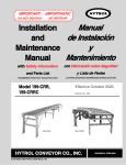
66
Equipment Photo
TM
Baker M6 Sidewinder DeDuster
User Manual
Ellington Industrial Supply, Inc.
P. O. Box 128
Ellington, Missouri 63638 USA
Web site: www.baker-online.com E-mail: [email protected]
Phone: (573) 663 – 7711 Fax: (573) 663 – 2787
TABLE OF CONTENTS
1
2
3
4
5
6
7
INTRODUCTION
Machine Purpose
Machine Function
Definition of Terms
Manual Contents Notice
Machine Specifications and Requirements
Warranty
Defective Parts
Service Policy
RULES FOR SAFE OPERATION
Safety Expectations for Operating Power Equipment
Control of Hazardous Energy – (Lockout / Tagout)
Machine Safety Decals
MACHINE FEATURES
SET-UP
Receiving and Inspection
Unpacking
Machine Positioning
Power and Utilities Requirements
Operator Training
OPERATION
Operator Control Station
Adjusting for Material Width and Length
Adjusting Brush Height
To Begin Processing Material
MAINTENANCE
General Clean Up
Inspection and Preventative Maintenance Checklist
Replacing Brushes
Air Assembly
De-Duster Chamber Access Hatch
PARTS AND SERVICE
Service Contact Information
Serial Number Location
Baker M6 DeDuster - Rev 1, 11/07; WWW.BAKER-ONLINE.COM
2
3
3
3
4
5
5
6
7
7
8
8
9
10
11
12
12
12
12
12
13
14
14
15
16-17
18
19
19
19-21
22
23
24
25-26
27
27
INTRODUCTION
Thank you and congratulations on the purchase of your new Baker M6 Sidewinder
DeDuster. It has been designed to be durable, productive and easy to use. When properly ran
and maintained, it will provide you with many years of profitable operation.
For safety reasons, and for your own best use of the Baker M6 Sidewinder DeDuster, we insist
that you read this manual fully, and constantly review and refer back to it as necessary.
No one should attempt to operate or perform maintenance on this equipment until they have
taken the time to read and understand the information contained in this manual.
** FAILING TO DO SO MAY RESULT IN SERIOUS INJURY **
Machine Purpose
The Baker M6 DeDuster was designed and manufactured for high production, capable of
running 140 linear feet per minute.
Machine Function
Your Baker M6 Sidewinder DeDuster features a non-slip board infeed, chain drive feed through
and two industrial size spherical nylon brushes that spin across the board surface for maximum
dust, particle and chip removal.
Baker M6 DeDuster - Rev 1, 11/07; WWW.BAKER-ONLINE.COM
3
Definition of Terms
All Stop
Safety button (typically “red”) designed to immediately shut-down machine
operation
Board Foot or
Board Feet
A form of measurement where one board foot equals the volume of a board 1
inch thick by 12 inches wide and 12 inches long (1” x 12” x 12” = 1 board foot)
CFM (cubic feet
per minute)
A measure of the volume of a substance flowing through air within a fixed
period of time
Conveyor
A mechanical apparatus (typically a belt, chain or rollers) that transports
material from one place to another
Edge Guide
A straight edge that is used to guide a piece of material
End Stop
A mechanism designed to stop the progress of an off-loading board
Fence (Arm)
A straight guide used to keep a log, cant or board a set distance from a blade
or cutter
Infeed
The side of the machine where the work piece (stringer, board, etc.) enters
Lift Point
A point where pressure can and should be applied for lifting
Linear Foot
A system of measurement in which only the length of the lumber is considered.
Live Rollers
A powered roll case that mechanically moves material
Lockout / Tagout Requires authorized employee(s) to lock and tag the energy-isolating device(s)
to prevent the release of hazardous energy in order to prevent injury to
employees, normally while performing maintenance or repairs
Lumber (board)
A longitudinal section of a log after the wany edges have been removed,
normally a 4-sided rectangular shaped piece
Off-load
The side of a machine where the work piece (stringer, board, etc.) exits
Production Rate
A produced or processed quantity measure with respect to another measured
quantity of time; for example number of boards per minute, board feet per hour,
per day, per week, etc.
Schematic
A structural or procedural diagram, typically of an electrical or hydraulic system
Yield
To generate a return for effort, an amount produced
Baker M6 DeDuster - Rev 1, 11/07; WWW.BAKER-ONLINE.COM
4
Manual Contents Notice
This manual is not totally comprehensive. It does not and cannot convey every possible
safety and operational problem that may arise while using this machine. The manual will
cover many of the basic and specific safety procedures needed in an industrial
environment.
All federal and state laws and any regulations having jurisdiction covering the safety
requirements for use of this machine take precedence over the statements in this manual.
Users of this machine must adhere to such regulations.
Machine Specifications and Requirements
Power
• (Three) 1 HP (.75 kw)
TEFC Motors
• (One) 2 HP (1.49 kw)
TEFC Motor
Dimensions & Weight
Length: 93” (236 cm)
Width: 98” (249 cm)
Height: 51” (129.5 cm)
Operating Air Pressure
• 45 psi (13mm)
• 1/2”, 120 psi incoming air Weight: 2,440 lbs (1,107kg)
pressure required
Production Rate
• Feed speed 140 linear feet per
minute
Sawdust Removal
• 6” (152mm) outlet; min. 1,500
CFM suction recommended at
dust removal chute
Capacity
Material Size:
• Board width: 3 ½” – 6”
• Board height: Max 2”
• Board length: Min – 28”
• Board length: Max – 62”
Baker M6 DeDuster - Rev 1, 11/07; WWW.BAKER-ONLINE.COM
5
Warranty
Ellington Industrial Supply, Inc. machinery is warranted against defects in material or
workmanship starting from the date of shipment from the manufacturing plant.
This warranty is given solely to the “original purchaser” of the equipment and is in no
way to be expressed or implied that it is transferable to any other parties without the
written consent and approval from the CEO or Sales Manager of Baker Products.
Our one (1) year warranty period covers all items built at our manufacturing facilities
including structural frame, cowlings, doors, shafting, dust chutes and guards.
We honor six (6) months of warranty coverage for miscellaneous vendor-purchasedsupplied items including bearings, chain, sprockets, hydraulic components, etc.
Ninety (90) days of warranty coverage is provided on all electrical parts. All electrical
components and wiring has been installed in accordance with the National Electrical
Code (NEC) of the United States of America.
Thirty (30) days of warranty coverage is provided for De-Duster brushes, which are
considered a wearable and consumable item.
Ellington Industrial Supply, Inc. does not warranty this machine to meet any other
requirements or jurisdiction of any electrical or safety codes of any other state,
municipality, other country or jurisdiction The purchaser assumes all risk and liability
whatsoever resulting from the use thereof whether used singularly or in conjunction with
other machinery or apparatus, including, but not limited to, all matters resulting from
sawdust generation.
Note: No warranty is provided on any electrical components or parts if equipment is
powered or connected to a roto-phase electrical converter in order to create a three
phase power supply for operational current from a single phase source.
Any change in materials, design, or performance intended to improve any product of
Ellington Industrial Supply, Inc. shall not obligate Ellington Industrial Supply, Inc. to
modify any previously manufactured equipment.
This manual may contain details that if not properly followed can affect the performance
of your equipment. You are responsible for proper use and maintenance of your
equipment and we reserve the right to deny warranty work if deemed to be caused by a
lack of proper maintenance or negligence by the owner or any of their employees.
Baker M6 DeDuster - Rev 1; 11/07 WWW.BAKER-ONLINE.COM
6
Defective Parts
Parts claimed defective must be returned freight prepaid, to our plant in Ellington,
Missouri. Any part determined defective due to faulty workmanship or materials will be
replaced or repaired (at our option) free of charge, F.O.B. our plant. This warranty does
not cover expendable items (i.e. drive belts, index-able cutter head inserts, chip
breakers, wedge blocks or mounting hardware, etc.). Except as expressly provided
herein, this warranty is in lieu of all other warranties, expressed or implied, including a
warranty of merchantability or fitness for a particular purpose. This warranty is “void” if
any part of the unit has been tampered with, modified, altered, or operated with parts
other than supplied or recommended by Ellington Industrial Supply, Inc. In no event
shall Ellington Industrial Supply, Inc. be liable for special, indirect, incidental or
consequential damages, however arising, including but not limited to, the loss of
earnings or the cost of downtime.
Service Policy
In the event that you have any problems, call us at (573) 663-7711 any time between
8:00 AM and 5:00 PM (CST), Monday through Friday. A member of our trained staff will
answer any questions you may have. We charge nothing for this service.
The only charge is for replacement parts not covered by warranty or after our inspection
we deem that the problem is due to operator error or lack of proper maintenance or
neglect.
If it is necessary for a member of our service department to visit your plant at your
request, there will be a charge for this service. Call our service department for current
prices.
Retain this Information for your Records
Model Number: ………………………………………...………………………….
Serial Number: …………………………………………………………………….
Date of Purchase: …………………………………………………………………
Power Source:…………..…………………….……………………………………
Dust Removal: ….……………………………………………………………….…
Ellington Industrial Supply, Inc.
P. O. Box 128
Ellington, Missouri 63638 USA
Web site: www.baker-online.com E-mail: [email protected]
Phone: (573) 663 – 7711 Fax: (573) 663 – 2787
Baker M6 DeDuster - Rev 1; 11/07 WWW.BAKER-ONLINE.COM
7
RULES FOR SAFE OPERATION
The purpose of safety symbols and signage is to draw your attention to real or possible
hazardous conditions that may exist when operating this equipment. Please remember that
safety symbols and signage alone do not eliminate danger and are not substitute for proper
training and education regarding operational hazards.
This symbol and warning indicates a potentially hazardous
situation, which, if not avoided, will result in death or serious injury.
This symbol and warning indicates a potentially hazardous
situation, which, if not avoided, could result in death or serious
injury.
This symbol and warning indicates a potentially hazardous
situation, which, if not avoided, may result in minor or moderate
injury.
This warning provides notice and instruction regarding a potentially
hazardous situation, which, if not avoided will result in serious injury
or death.
SAFETY EXPECTATIONS FOR OPERATING POWER EQUIPMENT
ALWAYS…
•
•
•
•
•
•
•
•
•
•
•
•
ENSURE THAT TRAINED PERSONNEL OPERATE, MAINTAIN AND REPAIR THIS EQUIPMENT
TURN POWER OFF AND LOCKOUT / TAGOUT PRIOR TO PERFORMING MAINTENANCE
KEEP WORK AREA CLEAN AND WELL LIGHTED TO MINIMIZE OR ELIMINATE HAZARDS
KEEP CHILDREN AND VISITIORS AWAY FROM OPERATING EQUIPMENT
OPERATE THE EQUIPMENT AT THE RATE IT WAS DESIGNED FOR
KEEP GUARDS IN PLACE WHEN OPERATING EQUIPMENT
REMOVE TOOLS BEFORE RESUMING OPERATION
USE PROPER EXTENSION CORD
WEAR PROPER APPAREL AND AVOID LOOSE CLOTHING AND ACCESSORIES THAT COULD
GET CAUGHT IN MOVING PARTS
ALWAYS WEAR SAFETY GLASSES AND HEARING PROTECTION
AVOID “KICK-BACK” BY KNOWING WHAT CONDITIONS CAN CREATE IT
CHECK DAMAGED PARTS AND REPAIR OR REPLACE THEM IMMEDIATELY
NEVER…
•
•
•
LEAVE MACHINERY RUNNING OR UNATTENDED, ALWAYS TURN POWER OFF
OPERATE EQUIPMENT WHEN TIRED, FATIGUED OR UNDER THE INFLUENCE OF DRUGS OR
ALCOHOL
ALLOW UNTRAINED PERSONNEL TO OPERATE, MAINTAIN OR REPAIR THIS EQUIPMENT
No list of safety expectations can ever be complete as every work environment is as
different as are the people operating the equipment.
Always keep safety as your highest priority and always use this machine with caution
and respect.
Baker M6 DeDuster - Rev 1, 11/07; WWW.BAKER-ONLINE.COM
8
Control of Hazardous Energy – (Lockout / Tagout)
Lockout / Tagout (LOTO) refers to specific practices and procedures to safeguard employees
from the unexpected energy, startup of machinery/equipment, or the release of hazardous
energy during service or maintenance activities.
This requires that a designated individual turn off and disconnect the machinery/equipment
from its energy source(s) before performing service or maintenance and that the authorized
employee(s) lock and tag the energy-isolating device(s) to prevent the release of hazardous
energy and take steps to verify that the energy has been isolated effectively.
List of Related Terms
Affected
Employee
Authorized
Employee
Energy
Source
Lockout
Servicing
and / or
Maintenance
Tagout
An employee whose job requires them to operate a machine or piece of
equipment on which service or maintenance is being performed.
A person who locks or implements a tagout system procedure on machines
or equipment to perform service or maintenance on that machine or
equipment. An authorized employee and an affected employee may be the
same person when the affected employee's duties also include performing
service or maintenance.
Any source of electrical, mechanical, hydraulic, pneumatic, chemical, thermal,
or other energy.
The placement of a lockout device (such as a lock) on an energy-isolating
device, in accordance with an established procedure that ensures the device
and the equipment cannot be operated until the lockout device is removed.
Workplace activities such as constructing, installing, setting up, adjusting,
inspecting, modifying, maintaining or servicing machines or equipment.
These activities include lubrication, cleaning or un-jamming of machines or
equipment, and making adjustments or tool changes where the employee
may be exposed to the unexpected energy, start-up of equipment or release
of hazardous energy.
The placement of a tagout device (such as a tag) on an energy-isolating
device, in accordance with an established procedure that ensures the device
and the equipment may not be operated until the tagout device is removed.
Example of lockout tags,
lockout hasp and keyed lock
1.
2.
3.
4.
5.
The Fatal Five Main Causes of
Lockout/Tagout Injuries
Failure to stop equipment
Failure to disconnect from a power
source
Failure to dissipate (bleed, neutralize)
residual energy
Accidental re-starting of equipment
Failure to clear work areas before restarting
Baker M6 DeDuster - Rev 1, 11/07; WWW.BAKER-ONLINE.COM
9
Machine Safety Decals ** Adhere to ALL Safety Warnings! **
Baker M6 DeDuster - Rev 1, 11/07; WWW.BAKER-ONLINE.COM
10
MACHINE FEATURES
We want to highlight the unique and special features of the Baker M6 Sidewinder
DeDuster.
Heavy-duty steel construction
Powerful electric motors
Air driven material pusher
Easy to set-up and fast feed speed
Heavy-duty nylon
spiral brushes
(enclosed)
Air driven
material pusher
Conveyor belt
infeed
Simple to use
operator control
station
Heavy-duty steel
construction
Chain driven
material transport
Baker M6 Sidewinder DeDuster
Baker M6 DeDuster - Rev 1, 11/07; WWW.BAKER-ONLINE.COM
11
SET-UP
Receiving and Inspection
Upon receipt and prior to signing transport carrier’s documents, conduct a walk-around
and visual inspection of your new equipment. Note any damage in writing upon the
carrier’s bill of lading and contact us immediately.
Note: All new equipment is assembled and thoroughly tested prior to shipment, however
damage may occur during transit, which could cause the machine to not operate correctly
during start-up.
Unpacking
If machine was delivered via flatbed trailer or container, remove straps or chains securing
it in place.
Remove lag screws, strapping, etc. that attaches the machine to the deck.
Transport machine to the installation site.
Machine Positioning (Placement, Leveling, Alignment)
For optimum performance, designate a solid and level foundation that is covered and dry,
free of environmental elements such as rain or snow that could cause electrical or slip
hazards.
We recommend you anchor the machine to the floor with the bolts in the footpads.
Provide a minimum of 3 feet of clear workspace in front of the electrical panel.
Power and Utilities Requirements
For safe and effective operation confirm your incoming voltage and available
amperage is equal to what the machine has been wired for at the factory.
A qualified electrician should complete electrical connections and check
for correct motor directional rotation.
Ensure all wiring, electrical connections and air hoses are located in a safe position
and away from any hazardous conditions.
Proper cutter rotation should be toward infeed of machine (front).
The “pusher” air pressure should be set at 45 psi.
Efficient dust and chip removal requires a minimum of 1,500 CFM suction at the
machine dust removal chute. This is an end user/owner responsibility.
Note: Failure to provide proper vacuum or suction may result in damage to machine or
operations personnel.
Baker M6 DeDuster - Rev 1, 11/07; WWW.BAKER-ONLINE.COM
12
Operator Training
According to many OSHA, ANSI, STATE, and LOCAL CODES, it is the EMPLOYER’S
RESPONSIBILITY to:
Permit only trained and authorized employees to operate and maintain
equipment.
Inspect and maintain guards, safety devices and start/stop controls.
Instruct, train and supervise the safe method of work.
Be sure personnel are properly trained and safety rules are clearly understood before
operating or performing maintenance.
Operator
Machine
Guards
Devices
Instructions
All five (5) of these listed items together make
up the safety system. Failure of any one of
these factors will increase accident potential.
FREE TRAINING ON PROPER SET-UP AND
OPERATION IS AVAILABLE ON SITE AT
THE MANUFACTURER’S FACILITY
Baker M6 DeDuster - Rev 1, 11/07; WWW.BAKER-ONLINE.COM
13
OPERATION
Operator Control Station
Prior to cycling any controls, ensure the area is clear of personnel and obstructions. Make
certain anyone required to work near the De-Duster is aware that the machine is in
operation.
** It is the operator’s responsibilities to ensure these safety conditions exist **
Descriptions
•
All Stop - Button designed to immediately shutdown machine operation.
•
Brush Start – Activates the de-dusting brushes.
•
Feed Start – Activates the feed conveyor and material transport.
•
Feed Stop – De-activates or stops the feed conveyor and material transport.
ALL STOP
BRUSH START
FEED START
Figure 14
Baker M6 DeDuster - Rev 1, 11/07; WWW.BAKER-ONLINE.COM
14
FEED STOP
Adjusting for Material Width and Length
Setting the M6 material width and length is simple and easy.
Loosen the width adjustment bolt
and nut and the pivot bolt and nut
(Figure 15).
Either use a measuring tape or
place a sample piece of material on
the conveyor and set width of
opening 1/4” greater than width of
material being processed.
Re-tighten the pivot bolt and nut
and adjustment bolt and nut.
Material flow
direction
End-stop with
limit switch
Adjustment
bolt
Pivot bolt
Figure 15
To set material length;
loosen the (3) bolts and
nuts that secure the end
stop and limit switch
(Figure 15 & 15A).
Align the mark to the
appropriate material
length, and then retighten the (3) nuts and
bolts (Figure 15A).
Note: There are notches
between each set of
material length numbers for
2-inch adjustment
increments.
Figure 15A
Baker M6 DeDuster - Rev 1, 11/07; WWW.BAKER-ONLINE.COM
15
Adjusting Brush Height
Ideal de-duster brush height is when the very tip of the brushes comes in contact with both
the top and bottom of the material being processed.
Note: Excessive and unnecessary brush wear will occur if the top or bottom de-dusting brush
is to close to the material being processed.
Figure 16A
Figure 16
A solid steel shaft secures the top and bottom spiral brushes in their proper position.
To adjust the height of the bottom brush, loosen the jam nuts on each side (Figures 16B
& 16C) and raise or lower the bottom brush height by turning the height adjustment nut.
Use a measuring tape to ensure gap is equal on both sides. See Figure 16A for ideal
bottom brush height.
When proper bottom brush height is achieved, re-tighten the jam nuts on each side.
Jam
Jam nuts
Nut
Bottom brush height
adjustment nut
Figure 16B
Figure 16C
Baker M6 DeDuster - Rev 1, 11/07; WWW.BAKER-ONLINE.COM
16
Adjusting Brush Height (continued)
To adjust the height of the top brush, loosen the jam nuts on top brush height adjustment
bolt (Figures 17 & 17A).
Raise or lower the top brush height by turning the adjustment bolt.
Note: Ideal de-duster brush height is when the very tip of the brushes comes in full contact
with both the top and bottom of the material being processed. Reference Figure 16A.
When proper top brush height is achieved, re-tighten the jam nuts.
Figure 17
Jam
Jam nuts
nut
Top brush height
adjustment bolt
Figure 17A
Baker M6 DeDuster - Rev 1, 11/07; WWW.BAKER-ONLINE.COM
17
To Begin Processing Material
Complete a visual inspection to ensure all guards/covers are in place and secure.
Turn on electrical power via the main electrical panel.
Turn on air supply.
Twist and pull up on the ALL STOP button (Figure 18).
Push the BRUSH START button to start the de-dusting brushes spinning. Wait until the
motor starts and is running at full speed, then push the FEED START button to start the
feed conveyor and material transport chains.
Begin feeding material onto the feed conveyor.
Note: Incoming material should not be stacked higher than the height of the fence / guide.
ALL STOP
BRUSH START
FEED START
FEED STOP
Figure 18
Incoming material
should not be
stacked higher
than the height of
the fence / guide
Figure 18A
Baker M6 DeDuster - Rev 1, 11/07; WWW.BAKER-ONLINE.COM
18
MAINTENANCE
General Clean Up
Note: Follow proper Lockout / Tagout procedures prior to cleaning or performing
maintenance on any part of the machine.
On a daily basis use an air-hose to blow-off the dust and wood chips that accumulate in,
on and around the machine.
The machine operator or clean-up person is closer to dangerous operating mechanisms
of the machine during clean up than during production – extra care should be taken
during this time.
Do NOT clean with flammable or combustible materials.
Follow applicable codes and standards with regards to:
Ventilation and monitoring of work area for excessive accumulation of hazardous
vapors
Wearing personal protective equipment for handling materials
Using proper procedure for disposing of all waste materials
Inspection and Preventative Maintenance Checklist
Frequency
Daily
(Approx. 8 hrs)
Weekly
(Approx. 40 hrs)
Weekly
Weekly
Every 3 Months
(Approx 480 hrs)
Important Notice:
Improper lubrication
will void warranty.
Recommendation
Complete a visual inspection of the machine before the beginning of each
production day and look for loose, worn, broken or defective parts.
Check the conveyor belt for cracks and ensure tension is “taut” with no more than
1/2” of deflection in the belt.
Check the material transportation chains and ensure tension is “taut” with no more
than a 1/2” of play in the tension of the chains.
Grease the material pusher linear rail bearings. We recommend JT-6 grease (no
more than 3 pumps).
Grease bearings using high temperature grease. We recommend JT-6 grease (no
more than 5 pumps).
Baker M6 DeDuster - Rev 1, 11/07; WWW.BAKER-ONLINE.COM
19
WEEKLY - Check conveyor band belt and ensure tension is “taut” with no more than 1/2”
of deflection in the belt. (Figure 20 & 20A)
Belt tension should
be “taut” with no more
than ½” of deflection
Figure 20A
Figure 20
Increase or decrease
belt
tension
tension
here
here
WEEKLY - Check the material transportation chains and ensure tension is “taut” with no
more than a 1/2” of play in the tension of the chains. (Figure 20B & 20C)
Figure 20B
Figure 20C
Increase or decrease chain
tension here
(1) chain per side, (2) total
Baker M6 DeDuster - Rev 1, 11/07; WWW.BAKER-ONLINE.COM
20
Increase or decrease chain
tension here
(1) chain per side, (2) total
WEEKLY - Grease the material pusher linear rail bearings. We recommend JT-6 grease
(no more than 3 pumps).
Figure 21A
Lubricate
Lubricate
linear
linear
rail rail
bearing
bearing
here
(2) per side,
here(4) total
(2) per side (4) total
Figure 21
EVERY 3 MONTHS - Grease bearings using high temperature grease. We recommend
JT-6 grease (no more than 5 pumps).
5
2
6
3
7
8
4
1
Figure 21B
Figure 21C
Baker M6 DeDuster - Rev 1, 11/07; WWW.BAKER-ONLINE.COM
21
Replacing Brushes
Note: Follow proper Lockout / Tagout procedures prior to cleaning or performing
maintenance on any part of the machine.
On the material entry side, remove the trantorque bushing, 2-bolt hole flange bearings,
bottom brush height adjustment plate, bolt and nut and top and bottom cover plates.
(Figure 22)
On the gearbox side, remove the top and bottom locking collars. (Figure 22A)
Slide the top brush out and remove the old brush and replace with a new brush and reattach the trantorque bushing.
Slide the bottom brush out and remove the old brush and replace with a new brush.
Slide the new bottom brush into place and secure it to the gearbox via the locking collar.
Slide the new top brush into place and secure it to the gearbox via the locking collar.
Replace the top and bottom cover plates followed by the 2-bolt flange bearings and the
bottom brush height adjustment plate, bolt and nuts.
Set top and bottom brush height per instructions on pages 16 & 17.
Flange bearing
Trantorque bushing
Gearbox locking collar
Cover plates
Figure 22
Bottom brush
height adjustment
plate, bolt and nut
Figure 22A
Baker M6 DeDuster - Rev 1, 11/07; WWW.BAKER-ONLINE.COM
22
Air Assembly
Figure 23
1/2”
1/2”,
incoming
120 psiair
incoming
supply connection
air supply
required
Operate at 45 psi
Figure 23A
Baker M6 DeDuster - Rev 1, 11/07; WWW.BAKER-ONLINE.COM
23
De-Duster Chamber Access Hatch
Note: Follow proper Lockout / Tagout procedures prior to cleaning or performing
maintenance on any part of the machine.
Access the de-duster chamber by removing the four (4) nuts highlighted below, then
remove the hatch cover.
With the hatch cover removed you can clean around the brushes or remove jammed
material.
When done performing a task in or around the de-duster chamber, return the hatch cover
to its proper position and re-secure via the four (4) nuts highlighted below.
Complete a visual inspection to ensure all other guards/covers are in place and secure
prior to resuming operation.
Hatch
Hatchcover
covernuts
nuts
(4)
(4)total
total
Hatch cover
Figure 24
Baker M6 DeDuster - Rev 1, 11/07; WWW.BAKER-ONLINE.COM
24
PARTS AND SERVICE
Part No.
Description
101003
Part No.
Description
101014
1-1/4” Bearing; ser
w/ring
101080
1” Bearing; 2-bolt flange
17/32” bolt hole
171035
1-1/4” Bearing; 2-bolt
flange 5/8” bolt hole
251105
2 piece locking collar –
1”
251111
Bushing trantorque; 1”
short
Bushing trantorque; 11/4” long
241148
242007
1/4” air quick plug
1/4” air muffler
241020
241125
1/4” street tee (brass
pipe fitting)
Bimba air cylinder; 11/2” x 10”
241112
241156
Norgren 1/4” filter/reg
w/bracket
1/4” x 1/8” hose barb
241198
241312
Air tank – 5 gallon
Baker M6 DeDuster - Rev 1, 11/07; WWW.BAKER-ONLINE.COM
25
Norgren 4-way solenoid
valve
Part No.
Description
121009
Part No.
Description
121010
Chain - #60 connector
link
Chain - #60 roller
131101
131110
Sprocket – 60B24F x 1”
Sprocket – 6020 x 1”
double
131111
133420
Sprocket – 6024 x 11/4”
133422
Sprocket – 60B15 x 5/8”
idler
111020
Belting – 5-1/2” slick top
3/8” thick
Sprocket – 60A24
151252
151250
Electric recessed push
button
Electric twist release ekill button
151253
151254
Electric N/C c-block red
101224
Electric N/C c-block
green
101276
Linear block SR30
161233
Linear rail
667795
Deduster brush; tube
style 12” OD x 62” wide
Baker M6 DeDuster - Rev 1, 11/07; WWW.BAKER-ONLINE.COM
26
Strip brush 5/16” x 3” H
x 6’ L
Service Contact Information
In the event that you have any problems, call us at (573) 663-7711 any time between 8:00
AM and 5:00 PM (CST), Monday through Friday.
Serial Number Location
The model and serial number are located on the front side of the machine near the material
entry conveyor.
Please refer to your serial number and model number when speaking to a
service technician or ordering replacement parts.
Baker M6 DeDuster - Rev 1, 11/07; WWW.BAKER-ONLINE.COM
27