1
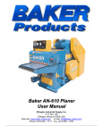
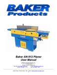
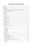
Equipment Photo TM Baker Model 18M User Manual Ellington Industrial Supply, Inc. P. O. Box 128 Ellington, Missouri 63638 USA Web site: www.baker-online.com E-mail: [email protected] Phone: (573) 663 – 7711 Fax: (573) 663 – 2787 TABLE OF CONTENTS TAB 1 2 3 4 5 6 7 8 9 SECTION AND SUB-SECTION TITLE INTRODUCTION Machine Purpose Machine Function Definition of Terms Manual Contents Notice Machine Specifications and Requirements Warranty Defective Parts Service Policy RULES FOR SAFE OPERATION Safety Expectations for Operating Power Equipment Control of Hazardous Energy – (Lockout / Tagout) Machine Safety Decals INSTALLATION Receiving and Inspection Unpacking Machine Moving Track and Machine Positioning SET-UP AND OPERATION Operator Training Blade Tensioning Blade Tracking / Blade Tracking Adjustment Getting Started Making the Cut USE OF LUMBER SCALE Calibrating Lumber Scale SECURING THE MILL FOR TRANSPORT MAINTENANCE General Clean-up Inspection and Preventative Maintenance GUIDES Setting and Adjusting the Guides PARTS AND SERVICE Parts Pictures and Description Service Contact Information Serial Number Location Baker Model 18M - Rev 1, 05/07; WWW.BAKER-ONLINE.COM 2 PAGE # 3 3 3 4 5 5 6 7 7 8 8 9 10 11 11 11 11 11-12 13 13 14 15 16 16-18 19 20 21 22 22 23-26 27 27 28 28 29 29 INTRODUCTION Thank you and congratulations on the purchase of your new Baker Model 18M. It has been designed to be durable, productive and easy to use. When properly used and maintained, it will provide you with many years of profitable operation. For safety reasons, and for your own best use of the Baker Model 18M, we must insist that you read this manual fully, and constantly review and refer back to it as necessary. No one should attempt to operate or perform maintenance on this equipment until they have been trained and taken the time to read and understand the information contained in this manual. Machine Purpose The Baker Model 18M is the economical choice for turning timber into valuable boards and squares. Machine Function The Baker Model 18M utilizes a 20-hp gasoline engine to turn the 18-inch band wheels that allow you to cut logs up to 30-inches in diameter. Utilizing Baker’s exclusive roller style guide system ensures the thin-kerf blade easily pushes through a variety of log species. And making blade height adjustments are easy and simple too. Baker Model 18M – Rev 1, 05/07; WWW.BAKER-ONLINE.COM 3 Definition of Terms Bark The outer-most protective layer of a tree composed of dead cork and other elements Band Saw A saw consisting of a continuous piece of flexible steel, with teeth on one side Board Foot or Board Feet A form of measurement where one board foot equals the volume of a board 1 inch thick by 12 inches wide and 12 inches long (1” x 12” x 12” = 1 board foot) Cant The 3 or 4 sided timber left over from a log, normally the center or core of the log Cant Hook A device used for rolling cants or logs Carriage A framework on wheels that allows movement of the saw back and forth past the log Edger A sawmill machine used to remove wany edges from flitches after they come off the sawmill, squaring the edges and ripping the flitch into lumber Fence (Arm) A straight guide used to keep a log, cant or board a set distance from a blade or cutter Flitch A longitudinal section of a log with wany edges Saw head or Head Saw The principle support structures on a sawmill that carries the engine, wheels and band blade used for the initial breakdown of a log Kerf The groove or thickness of the path cut by the saw teeth; the total amount of sawdust removed during a single cut Log Bunk A cross support that a log is loaded onto Lumber (board) A longitudinal section of a log after the wany edges have been removed, normally a 4-sided rectangular shaped piece Production Rate A produced or processed quantity measure with respect to another measured quantity of time; for example number of boards per minute, board feet per hour, per day, per week, etc. Slab The exterior portion of a log removed by the saw, having one flat and one rounded portion of a log Thin Kerf A relative term, typically referencing band saw blades which are usually thinner than circular saw blades thus resulting in greater lumber recovery, accuracy and smooth finish Wany Waning or diminished in some parts; not of uniform size throughout; sawed boards or timber that is tapered or uneven, from being cut too near the outside of the log bark Yield To generate a return for effort, an amount produced Baker Model 18M – Rev 1, 05/07; WWW.BAKER-ONLINE.COM 4 Manual Contents Notice This manual is not totally comprehensive. It does not and cannot convey every possible safety and operational problem that may arise while using this machine. The manual will cover many of the basic and specific safety procedures needed in an industrial environment. All federal and state laws and any regulations having jurisdiction covering the safety requirements for use of this machine take precedence over the statements in this manual. Users of this machine must adhere to such regulations. Machine Specifications and Requirements Power: 20-hp gasoline engine with 12-volt battery and electric start Band Wheels: 18-inch diameter Band Blade: 13-feet, 5-inches long by 1-1/4 inch wide Blade Thickness: 0.035-inch Blade Kerf: 0.080-inch Guides: Roller blade guide system for higher production, accuracy and extended blade life Track Length: 16-feet standard; 20-feet optional Machine Width: 74-inches Machine Height: 51-inches (with trailer axle removed) Combined Weight: Standard track length and saw head approximately 800 pounds Production Rate: Varies according to type of material, thickness of cut, and rate of speed material is cut. Baker Model 18M – Rev 1, 05/07; WWW.BAKER-ONLINE.COM 5 Warranty Ellington Industrial Supply, Inc. machinery is warranted against defects in material or workmanship starting from the date of shipment from the manufacturing plant. This warranty is given solely to the “original purchaser” of the equipment and is in no way to be expressed or implied that it is transferable to any other parties without the written consent and approval from the CEO or Sales Manager of Baker Products. Our one (1) year warranty period covers all items built at our manufacturing facilities including structural frame, cowlings, doors, shafting, dust chutes, trailer axle and guards. We honor six (6) months of warranty coverage for miscellaneous vendor-purchasedsupplied items including bearings, chain, sprockets, hydraulic components, etc. Ninety (90) days of warranty coverage is provided on all electrical parts. All electrical components and wiring has been installed in accordance with the National Electrical Code (NEC) of the United States of America. Ellington Industrial Supply, Inc. does not warranty this machine to meet any other requirements or jurisdiction of any electrical or safety codes of any other state, municipality, other country or jurisdiction The purchaser assumes all risk and liability whatsoever resulting from the use thereof whether used singularly or in conjunction with other machinery or apparatus, including, but not limited to, all matters resulting from sawdust generation. Note: No warranty is provided on any electrical components or parts if equipment is powered or connected to a roto-phase electrical converter in order to create a three phase power supply for operational current from a single phase source. Any change in materials, design, or performance intended to improve any product of Ellington Industrial Supply, Inc. shall not obligate Ellington Industrial Supply, Inc. to modify any previously manufactured equipment. This manual may contain details that if not properly followed can affect the performance of your equipment. You are responsible for proper use and maintenance of your equipment and we reserve the right to deny warranty work if deemed to be caused by a lack of proper maintenance or negligence by the owner or any of their employees or other persons allowed to use the equipment. Baker Model 18M - Rev 1, 05/07; WWW.BAKER-ONLINE.COM 6 Defective Parts Parts claimed defective must be returned freight prepaid, to our plant in Ellington, Missouri. Any part determined defective due to faulty workmanship or materials will be replaced or repaired (at our option) free of charge, F.O.B. our plant. This warranty does not cover expendable items (i.e. drive belts, band wheels, blades, cutters, guides, etc.). Except as expressly provided herein, this warranty is in lieu of all other warranties, expressed or implied, including a warranty of merchantability or fitness for a particular purpose. This warranty is “void” if any part of the unit has been tampered with, modified, altered, or operated with parts other than supplied or recommended by Ellington Industrial Supply, Inc. In no event shall Ellington Industrial Supply, Inc. be liable for special, indirect, incidental or consequential damages, however arising, including but not limited to, the loss of earnings or the cost of downtime. Service Policy In the event that you have any problems, call us at (573) 663-7711 any time between 8:00 AM and 5:00 PM (CST), Monday through Friday. A member of our trained staff will answer any questions you may have. We charge nothing for this service. The only charge is for replacement parts not covered by warranty or after our inspection we deem that the problem is due to operator error or lack of proper maintenance or neglect. If it is necessary for a member of our service department to visit your plant at your request, there will be a charge for this service. Call our service department for current prices. Retain this Information for your Records Model Number: ……………………………………………………..……………. Serial Number: ……………………………………………………………………. Date of Purchase: ………………………………………………………………… Engine Make and Model: ……...………………………………………………… Ellington Industrial Supply, Inc. P. O. Box 128 Ellington, Missouri 63638 USA Web site: www.baker-online.com E-mail: [email protected] Phone: (573) 663 – 7711 Fax: (573) 663 – 2787 Baker Model 18M - Rev 1, 05/07; WWW.BAKER-ONLINE.COM 7 RULES FOR SAFE OPERATION The purpose of safety symbols and signage is to draw your attention to real or possible hazardous conditions that may exist when operating this equipment. Please remember that safety symbols and signage alone do not eliminate danger and are not substitute for proper training and education regarding operational hazards. This symbol and warning indicates a potentially hazardous situation, which, if not avoided, will result in death or serious injury. This symbol and warning indicates a potentially hazardous situation, which, if not avoided, could result in death or serious injury. This symbol and warning indicates a potentially hazardous situation, which, if not avoided, may result in minor or moderate injury. This warning provides notice and instruction regarding a potentially hazardous situation, which, if not avoided will result in serious injury or death. SAFETY EXPECTATIONS FOR OPERATING POWER EQUIPMENT ALWAYS… • • • • • • • • • • • • ENSURE THAT TRAINED PERSONNEL OPERATE, MAINTAIN AND REPAIR THIS EQUIPMENT TURN POWER OFF AND LOCKOUT / TAGOUT PRIOR TO PERFORMING MAINTENANCE KEEP WORK AREA CLEAN AND WELL LIGHTED TO MINIMIZE OR ELIMINATE HAZARDS KEEP CHILDREN AND VISITIORS AWAY FROM OPERATING EQUIPMENT OPERATE THE EQUIPMENT AT THE RATE IT WAS DESIGNED FOR KEEP GUARDS IN PLACE WHEN OPERATING EQUIPMENT REMOVE TOOLS BEFORE RESUMING OPERATION USE PROPER EXTENSION CORD WEAR PROPER APPAREL AND AVOID CLOTHING AND ACCESSORIES THAT COULD GET CAUGHT IN MOVING PARTS ALWAYS WEAR SAFETY GLASSES AND HEARING PROTECTION AVOID “KICK-BACK” BY KNOWING WHAT CONDITIONS CAN CREATE IT CHECK DAMAGED PARTS AND REPAIR OR REPLACE THEM IMMEDIATELY NEVER… • • • LEAVE TOOL RUNNING OR UNATTENDED, ALWAYS TURN POWER OFF OPERATE EQUIPMENT WHEN TIRED, FATIGUED OR UNDER THE INFLUENCE OF DRUGS OR ALCOHOL ALLOW UNTRAINED PERSONNEL TO OPERATE, MAINTAIN OR REPAIR THIS EQUIPMENT No list of safety expectations can ever be complete as every work environment is as different as the people operating it. Always keep safety as your highest priority and always use this machine with caution and respect. Baker Model 18M - Rev 1, 05/07; WWW.BAKER-ONLINE.COM 8 Control of Hazardous Energy – (Lockout / Tagout) Lockout / Tagout (LOTO) refers to specific practices and procedures to safeguard employees from the unexpected energy, startup of machinery/equipment, or the release of hazardous energy during service or maintenance activities. This requires that a designated individual turn off and disconnect the machinery/equipment from its energy source(s) before performing service or maintenance and that the authorized employee(s) lock and tag the energy-isolating device(s) to prevent the release of hazardous energy and take steps to verify that the energy has been isolated effectively. List of Related Terms An employee whose job requires them to operate a machine or piece of Affected equipment on which service or maintenance is being performed. Employee A person who locks or implements a tagout system procedure on machines or Authorized equipment to perform the service or maintenance on that machine or Employee equipment. An authorized employee and an affected employee may be the same person when the affected employee's duties also include performing service or maintenance. Any source of electrical, mechanical, hydraulic, pneumatic, chemical, thermal, Energy or other energy. Source The placement of a lockout device (such as a lock) on an energy-isolating Lockout device, in accordance with an established procedure that ensures the device and the equipment cannot be operated until the lockout device is removed. Workplace activities such as constructing, installing, setting up, adjusting, Servicing inspecting, modifying, and maintaining and/or servicing machines or and / or Maintenance equipment. These activities include lubrication, cleaning or un-jamming of machines or equipment, and making adjustments or tool changes where the employee may be exposed to the unexpected energy, start-up of equipment or release of hazardous energy. The placement of a tagout device (such as a tag) on an energy-isolating Tagout device, in accordance with an established procedure that ensures the device and the equipment may not be operated until the tagout device is removed. Example of lockout tags, lockout hasp and keyed lock 1. 2. 3. 4. 5. The Fatal Five Main Causes of Lockout/Tagout Injuries Failure to stop equipment Failure to disconnect from a power source Failure to dissipate (bleed, neutralize) residual energy Accidental re-starting of equipment Failure to clear work areas before restarting Baker Model 18M - Rev 1, 05/07; WWW.BAKER-ONLINE.COM 9 Machine Safety Decals ** Adhere to ALL Safety Warnings! ** Baker Model 18M - Rev 1, 05/07; WWW.BAKER-ONLINE.COM 10 INSTALLATION Receiving and Inspection Upon receipt and prior to signing carrier’s documents, conduct a walk-around and visual inspection of your new equipment. Note any damage in writing upon the carrier’s bill of lading and contact Baker Products immediately. Failure to do so could reverse damage charges back to receiving party. Note: All new equipment is assembled and thoroughly tested prior to shipment, however damage may occur during transit, which could cause the machine to not operate correctly during start-up. Pictured is the 18HP (electric and hydraulic powered mill) that operates on the same frame as the 18M Unpacking If machine was delivered via flatbed trailer, remove straps or chains securing it in place. If machine was delivered by crate, carefully remove upper crating materials from the base skid. Remove lag screws, strapping, etc. that attaches the machine to the skid. Machine Moving If required, lift machine at the indicated lift points only. o Use a safety strap to avoid tip-over. Otherwise use the trailer / tow hitch provided. Transport machine to the operation site. Lift points – center the saw head over the axle and equally space forks under the carriage frame for a balanced lift Track and Machine Positioning (Placement, Leveling, Alignment) For best performance, choose a solid, level foundation that is free of environmental elements such as rain or snow that could cause mechanical or slip hazards. A level cement pad works best, but square timbers also work well under the leveling legs. We recommend an open or well-ventilated area that will exhaust engine emissions. Provide a minimum of 4 feet of clear workspace around the entire perimeter of the track. Remove trailer axle and store in a dry location. Assemble the track so that the log clamps are on the same side of the mill that the operator will work from. Bolt the sections of track together with the nuts and bolts provided, ensuring the track is flush where the ends are bolted together. Level the track front to back and side to side. For optimal results, the Model 18M must be level and free of crowns or dips for the length of the adjoined tracks. Consider the use of a string line to check for straightness along the track length. Raise the head a minimum of 3 inches and roll from end to end to verify the track is aligned properly for smooth operation. Adjust or re-level as necessary. Baker Model 18M - Rev 1, 05/07; WWW.BAKER-ONLINE.COM 11 Track and Machine Positioning (continued) To remove the detachable section of track, loosen the leveling legs (2 per side) and set it aside while you remove the trailer axle Figure 12 Figure 12A After the trailer axle has been remremoved oved andand the the frame frame is rest is ing positioned on a solid on surface, a solid work placesurface, the detachabl place the edetachable section of section track over of thetrack trailer over hitch theand trailer align hitch theand holes align and tighten the holes via and the bolts tighten and vianuts the bolts and provided nuts provided Track end stops Baker Model 18M - Rev 1, 05/07; WWW.BAKER-ONLINE.COM 12 SET-UP AND OPERATION Operator Training According to many OSHA, ANSI, STATE, and LOCAL CODES, it is the EMPLOYER’S RESPONSIBILITY to: ¾ Permit only trained and authorized employees to operate and maintain equipment. ¾ Inspect and maintain guards, safety devices and start/stop controls. ¾ Instruct, train and supervise the safe method of work. Be sure personnel are properly trained and safety rules are clearly understood before operating or performing maintenance. 9 9 9 9 9 Operator Machine Guards Devices Instructions All of these together make up the safety system. Failure of any one of these factors will increase accident potential. Note: Prior to start-up and then again after two weeks, check that all nuts and bolts are tight. Then follow the instruction and schedule outlined in the Inspection and Preventative Maintenance section. FREE TRAINING ON PROPER SET-UP AND OPERATION IS AVAILABLE ON SITE AT THE MANUFACTURER’S FACILITY Baker Model 18M - Rev 1, 05/07; WWW.BAKER-ONLINE.COM 13 Blade Tensioning Your mill is shipped to you with minimal blade tension to help avoid the development of flat spots that could cause the blade to track improperly on the band wheels. Note: For the Honda 20-hp engine this requires the key to be removed from the ignition and a “do not operate” tag attached to the engine. Open and remove the two (2) cowling doors. Verify that the back of the blade is flush with the back of each band wheel (Figure 14). To tension the blade, turn the t-handled all-thread bolt clockwise until the factory set tension marks align (Figure 14A, 14C). Carefully rotate the band wheel counter clockwise to ensure blade tracks properly. o See next section (Blade Tracking) if an adjustment is necessary. Once proper tension and tracking is achieved, return and secure the cowling doors. If necessary, refer to Setting and Adjusting the Roller Guides, page 25. Back of band blade should be flush with back of band wheels De-tensioned blade, marks not aligned Figure 14 Figure 14B Blade tension adjusting t-handle Pre-set factory blade tension mark Marking aligned = proper tension Figure 14C Figure 14A Baker Model 18M - Rev 1, 05/07; WWW.BAKER-ONLINE.COM 14 Blade Tracking The blade tracking is set at the factory prior to shipment, but it may periodically have to be adjusted or reset. Most band blades will vary on how they track due to blade material. Note: For the Honda 20-hp engine this requires the key to be removed from the ignition and a “do not operate” tag attached to the engine. Blade Tracking Adjustment Note: If the blade is tracking out just a little after running for a few minutes, don’t be alarmed; most blades do this as they self-adjust to the contour of the wheels. Open and remove the two (2) cowling doors. If the blade is running out or in more than 1/32” you should try three or more blades or another box of blades before making any tracking adjustments. This will help you determine whether it’s the blade(s) or something else that is affecting tracking. If the blade is tracking outward and you want to move blade tracking “inward”, adjust the top and bottom band wheel tracking bolts by loosening the center jamb nut and then tighten the bolts via the bolt head one (1) revolution to the right (Figure 15 and 15A). Next make the same adjustments on the opposite wheel by loosening the center jamb nut and then tighten the bolts via the bolt head one (1) revolution to the right. After tracking bolts have been adjusted, rotate the idler wheel several rotations counterclockwise and look at the blade gullet in relation to the front face of the wheel to ensure tracking is consistent. Continue to adjust and fine tune as necessary. If the blade is tracking inward and you want to move blade tracking “outward”, loosen the center jamb nut and then loosen the tracking adjustment bolts one (1) revolution via the bolt head. Repeat the same steps for the opposite side wheel. Once proper blade tracking has been achieved, re-tighten the jamb nuts (2 per side) for both the pull and idler wheel. Return and fasten the cowling doors. Bolt Head Jamb Nut Tracking Tracking Adjustment adjustmentBolts bolts Located behind each band wheel Two (2) per band wheel Figure 15A Figure 15 Baker Model 18M - Rev 1, 05/07; WWW.BAKER-ONLINE.COM 15 Getting Started Log loading options for this mill include the use of two 4” x 4” or 4” x 6” timbers or the use of a forklift or front-end loader. After loading a log onto the track, roll it against the raised fence arms and secure it into position with the log clamp by turning the handle clockwise and screwing the clamp into the log. Note: Ensure top of fence arms and log clamp are positioned safely below the height of the blade. Failure to do so will result in blade damage. Log clamp Figure 16 Figure 16A Raised fence arms Making the Cut To START Processing Step 1: Prior to starting the engine, complete a visual inspection to ensure all guards and covers are in place and secure. Step 2: Loosen the t-handle securing the moveable guide and slide it in or out until it is slightly (no more than 2 inches) wider than the maximum width of the log. Tighten the t-handle after proper adjustment has been made (Figure 15B & 15C). Note: As you cut slabs and boards or squares from your log, you will want to bring your guides in closer to ensure the best performance and quality cuts. Backside view of t-handle securing moveable guide Guides properly positioned for quality cut Figure 16B Figure 16C Baker Model 18M - Rev 1, 05/07; WWW.BAKER-ONLINE.COM 16 Making the Cut (continued) Step 3: Start the engine and let it idle and warm up for at least 2 minutes. Maximize engine throttle when ready to cut. Engine choke Pull out to choke for starting and warm-up Push in for normal operation Engine throttle Turn key to right to start engine Turtle = slow Rabbit = Fast Figure 17 Step 4: Engage drive belt by pulling down on belt tension arm handle (Figure 17A). Release tension by pushing up on handle. Figure 17A Step 5: Adjust blade height so you will only remove the top, barky portion of the log to create a slab. Note: Typically you want to remove enough of a slab to open up a 4-inch face on the log. Therefore on the next cut you will produce at least a 4-inch wide flitch to be edged into a 4” wide board. This is a recommendation only. Depth and width of cut is subject to your desired finished product dimensions. Baker Model 18M - Rev 1, 05/07; WWW.BAKER-ONLINE.COM 17 Making the Cut (continued) Step 6: Place your left hand on the center carriage cross-member and your right hand on the push/pull handle (Figure 18) and move the head forward in the direction of the back of the log. Allow the carriage to move forward and the blade to begin making its cut. Listen to the engine and if it begins to “bog-down” slow your advancement into and through the log. Step 7: Once you’ve completed your cut, remove the slab and raise the saw head enough to clear the log and return the head carriage to the front of the log to make your next cut. Step 8: Adjust saw head height to desired board thickness, then make cut and remove flitch. Step 9: Raise the saw head and return carriage to the front of the log and idle the engine. Step 10: Release the log clamps and use a cant hook to turn the log 1/4 turn to the right so the flat edge is against the fence arms. Ensure the fence arms and log clamps are well below the height of the passing blade before tightening. Step 11: Repeat Step 6 through 10 until you’ve cut your log into the desired lumber sizes. Place left hand on center carriage cross-member to move carriage forward and backward Place right hand on push/pull handle Figure 18 To STOP Processing Step 1: Disengage the belt drive by moving the tensioning handle upward, relieving pressure from the belt (Figure 17A on page 17). Step 2: Reduce engine throttle to a minimum idling state, then turn the key to the off position. Note: The band blade does not stop spinning automatically and will coast to a stop. Note: Consider de-tensioning the blade if your machine is going to sit idle for a 24-hour period or longer. Baker Model 18M - Rev 1, 05/07; WWW.BAKER-ONLINE.COM 18 USE OF LUMBER SCALE Your Baker Model 18M is equipped with a lumber scale, which simplifies the lumber dimensioning process. The scale incorporates four separate scales with blade kerf factoredin for each increment. Our 1-1/4” x 0.035” Lennox blades have 0.080-inch kerf. SCALE 4/4 4/4 HWD (hardwood) 6/4 8/4 RESULTING THICKNESS 1” thick boards 1-1/8” thick boards 1-1/2” thick boards 2” thick boards Actual inches row (Standard ruler scale – 1”, 1/2”, 1/4”, 1/8” and 1/16” graduations) 4/4 Scale Row = 1” lumber 4/4 HWD Scale Row = 1-1/8” lumber 6/4 Scale Row = 1-1/2” lumber 8/4 Scale Row = 2” lumber Line shows actual blade height as measured from the top of log bunks and is used for scaling Figure 19 Baker Model 18M - Rev 1, 05/07; WWW.BAKER-ONLINE.COM 19 Calibrating Lumber Scale To calibrate the lumber scale actual inches row, raise the band blade approximately 12 inches above the log bunks. Position the band blade over one of the center log bunks and take a measurement from the top of the log bunk to the bottom tooth of the blade. Raise bottom of band blade approximately 12 inches above top of log bunk Loosen lock collar and bolt to raise or lower the measurement stick until it reads the same as your measurement from the top of the bunk to the bottom of the band blade Figure 20 Loosen the screw holding the collar on the measurement stick and then loosen the bolt holding the measurement stick in place. Raise or lower the measurement stick until the red line/mark reads the same as the measurement you took from the top of the log bunk to the bottom tooth of the band blade. Once the two measurements match one another, tighten the bolt holding the measurement stick in place, and then tighten the screw holding the collar around the measurement stick so that it cannot slide downward during use. To verify, saw a timber into a 4-sided square and measure the actual size of the timber in correlation to the actual inches on the lumber scale. For example a 12-inch x 12-inch square. Baker Model 18M - Rev 1, 05/07; WWW.BAKER-ONLINE.COM 20 Figure 20A SECURING THE MILL FOR TRANSPORT The mill requires a 2" trailer hitch ball on the tow vehicle to properly fit the trailer coupler. Ensure tires are properly inflated to the correct pressure, as stated on the sidewall. Position carriage over the axel and secured in place by aligning the holes of the hinged frame bracket to those on the carriage head frame and inserting two (2) bolts through the aligned holes. Tighten firmly with lock washers and nuts (Figure 21). Ensure the additional section of track fits squarely on the main frame is secured in place via the front leveling legs per the illustration below (Figure 21A). Ensure all fences and clamp arms are raised and secured in place. Ensure trailer hitch is properly fastened with cotter pin in place on the hitch latch and the two safety chains and brake activation pull cable are securely fastened to the tow vehicle. Rotate trailer jack to the horizontal position and secure in place with the locking pin. Verify that the brake lights and turn signals work properly prior to towing. NOTE: Baker Products will not be held responsible for any injury or damage resulting from failure to follow all safety precautions associated with vehicle towing. It is the customer’s responsibility to ensure that the mill meets all laws associated with towed equipment in their respective state or local. Insurance coverage is not provided by the manufacturer, but should be covered by the tow vehicle being used for transport. Ensure the additional section of track fits squarely on the main frame and is secured in place via the front leveling legs. Figure 21A Figure 21 Hinged Hinged bracket bracket located located behind behind tire tire and attached to the frame Align bracket holes with carriage head frame holes and insert bolts and secure with washers and lock nuts Baker Model 18M - Rev 1, 05/07; WWW.BAKER-ONLINE.COM 21 MAINTENANCE General Clean Up Follow proper Lockout / Tagout procedures prior to performing any maintenance or repair on the machine. On a daily basis, use an air-hose to blow-off the dust and wood chips that accumulate in and around the machine. If air is not available a soft brush will work as well. Machine operator is closer to operating mechanism of the machine during maintenance clean up more than during production – extra care should be taken. During daily clean up and daily maintenance of the machinery it is advised that the operator complete a visual inspection of the equipment to look for anything that may have been damaged or become loose during normal use. DO NOT clean with flammable or combustible materials. Follow applicable codes and standards with regards to: Ventilation and monitoring of work area for excessive accumulation of hazardous vapors Wearing personal protective equipment for handling materials Using proper procedure for disposing of all waste materials Baker Model 18M - Rev 1, 05/07; WWW.BAKER-ONLINE.COM 22 Important Notice: Improper lubrication will void warranty. Inspection and Preventative Maintenance Follow proper Lockout / Tagout procedures prior to performing any maintenance or repair on the machine. Note: For the Honda 20-hp engine this requires the key to be removed from the ignition and a “do not operate” tag attached to the engine. Frequency Daily Daily Daily Daily Daily Weekly Weekly Weekly Monthly Recommendation Use an air-hose or soft brush to remove wood chips that accumulate in and around the machine and along the track. Check engine fuel and blade lubricant level by inspecting the fluid level on the side of the respective tanks. (Figure 24 & 24A, page 24) Clean the idler and pull wheels by using an air hose, brush or by wiping them down with a rag or shop towel, freeing them of dust and debris. Grease the roller guides. We recommend JT-6 grease (no more than 3 pumps). (Figure 24B& 24C, page 24) Clean & inspect the roller guides. Damaged or excessively worn roller guides should be replaced. (Figure 24B & 24C, page 24) Check idler and pull wheel bearings for wear. Signs of wear include excessive heat, squeaking sound or looseness. (Figure 25 & 25A, page 25) Grease the idler and pull wheel bearings. We recommend JT-6 grease (no more than 5 pumps). (Figure 25 & 25A, page 25) Grease the raise / lower shaft bearings. We recommend JT-6 grease (no more than 5 pumps). (Figure 25B, page 25) Check drive belts for wear and ensure belt tension is “taut” with no more than 1/2” deflection when engaged. (Figure 26, page 26) ** RETURN ALL GUARDS AND COVERS PRIOR TO RESUMING OPERATION! ** Baker Model 18M - Rev 1, 05/07; WWW.BAKER-ONLINE.COM 23 Inspection and Preventative Maintenance (continued) Daily Check engine fuel and blade lubricant level by inspecting the fluid level on the side of the respective tanks. Engine gas tank Keep a minimum of 1/2 full Figure 24 Figure 24A Grease the roller guides. We recommend JT-6 grease (no more than 3 pumps daily). Grease Fitting Grease Fitting Figure 24B Figure 24C Clean & inspect the roller guides. Damaged or excessively worn roller guides should be replaced. Baker Model 18M - Rev 1, 05/07; WWW.BAKER-ONLINE.COM 24 Inspection and Preventative Maintenance (continued) Weekly Check idler and pull wheel bearings for wear. Signs of wear include excessive heat, squeaking sound or looseness. Grease the idler and pull wheel bearings. We recommend JT-6 grease (no more than 5 pumps). Figure 25 Figure 25A Bearing Grease Fittings Idler Wheel Bearings and Grease Fittings Pull Wheel Bearings and Grease Fittings Weekly Grease the raise / lower shaft bearings. We recommend JT-6 grease (no more than 5 pumps). Grease Fitting Raise/Lower Shaft Figure 25B Baker Model 18M - Rev 1, 05/07; WWW.BAKER-ONLINE.COM 25 Grease Fitting Inspection and Preventative Maintenance (continued) Monthly Check drive belts for wear and ensure belt tension is “taut” with no more than 1/2” deflection when engaged. Check drive belts for wear Belt tension should be “taut” with no more than 1/2” of deflection when engaged Figure 26 NOTE: Pictured is a Model 18HP with an electric motor power source. Same belt tensioning principle applies whether power source is electric, gasoline or diesel. NOTE: If belts are slipping during start-up that may be a sign of loose belts. SAFETY REMINDER ** RETURN ALL GUARDS AND COVERS PRIOR TO RESUMING OPERATION! ** Baker Model 18M - Rev 1, 05/07; WWW.BAKER-ONLINE.COM 26 GUIDES Setting and Adjusting the Roller Guides When properly set and utilized, your band blade guides will provide better blade control and longer blade life. To adjust or re-align the left/moveable roller guide, loosen the t-handle holding the guide arm in place. (If adjusting the stationary right side guide, proceed to the next step). Loosen the bolts (A) holding the roller guide in its vertical and horizontal position. These bolts serve as a roller guide tilting and/or leveling function. Loosen the bolts (B) that hold the roller guide back raised edge against the back of the blade. Set the roller guides by ensuring the back raised edge of the guide is spaced 1/8-inch behind the back of the blade. Re-tighten the bolts (B) after adjustment and alignment is complete. The roller guide should rest evenly on the blade with no down force pressure applied initially. If a tilt adjustment is required and you haven’t already done so, loosen the top and bottom tilting bolts (A) and adjust accordingly until you are satisfied the roller guides are level and even with the horizontal blade surface, then re-tighten the jamb nuts. Adjust the left/moveable guide to the required cutting width for your material and tighten the t-handle. Doing so will now result in a small amount of down pressure on the blade. Down pressure also occurs when the opposite side guide post bolt is tightened. Ensure any remaining bolts, nuts and jam nuts associated with the left and right roller guide assemblies, including the guide arms are tight prior to resuming operations. Moveable guide T-handle Loosen Loosen to to adjust adjust roller roller guide tilt/leveling guide tilt/leveling Figure 27 Figure 27A A A Loosen to Loadjust osen to abdack just bac edgeedge of k edge of roller guide of roller ralignment oller guide guide alignment Loosen to to back of alignment back blade ttoadjust b k off A B A B A A A A Loosen to adjust roller guide tilt/leveling Left side – moveable guide assembly Right side – stationary guide assembly Baker Model 18M - Rev 1, 05/07; WWW.BAKER-ONLINE.COM 27 PARTS AND SERVICE Part Picture Description Part Picture 111135 Description 111112 B-56 BELT B-90 BELT 133406 133408 40A45 x 3/4” SPROCKET 40B9 x 5/8” SPROCKET 133409 131025 40B12F x 1” SPROCKET 40B10 x 3/4” SPROCKET 131042 133410 40A15 x 5/8” SPROCKET 50BB13H x ½” IDLER SPROCKET 101380 101384 1 - 7/16” 2 BOLT FLANGE BEARING 603 – 1/4V THRUST BEARING 101120 101014 1” 2 BOLT FLANGE 17/32” BOLT HOLE BEARING 1” PILLOW BLOCK BEARING 121185 121007 #50 CHAIN ROLLER #50 CHAIN CONNECTOR LINK 121003 121004 #40 CHAIN CONNECTOR LINK #40 CHAIN ROLLER 664903 141449 CARRIAGE V WHEEL RIGHT or LEFT ROLLER GUIDE ASSEMBLY OSD-362D x 1” TORQUE LIMITER 13’-5” x 1-1/4” LENNOX BAND BLADES 271190 Baker Model 18M - Rev 1, 05/07; WWW.BAKER-ONLINE.COM 28 Service Contact Information In the event that you have any problems, call us at (573) 663-7711 any time between 8:00 AM and 5:00 PM (CST), Monday through Friday. Serial Number Location The model and serial number are located on the top left corner of the machine. Please refer to your serial number and model number when speaking to a service technician or ordering replacement parts. Baker Model 18M - Rev 1, 05/07; WWW.BAKER-ONLINE.COM 29