1
SIMIT Virtual Controller (VC) - User
Manual
Operating Manual
11/2014
A5E32889042-AB
Start
1
Basics of SIMIT VC
2
Creating a new emulation
project
3
Generating an emulation
project
4
Special use cases
5
Error handling, diagnostics
and recovery
6
Abbreviations
7
Legal information
Warning notice system
This manual contains notices you have to observe in order to ensure your personal safety, as well as to prevent
damage to property. The notices referring to your personal safety are highlighted in the manual by a safety alert
symbol, notices referring only to property damage have no safety alert symbol. These notices shown below are
graded according to the degree of danger.
DANGER
indicates that death or severe personal injury will result if proper precautions are not taken.
WARNING
indicates that death or severe personal injury may result if proper precautions are not taken.
CAUTION
indicates that minor personal injury can result if proper precautions are not taken.
NOTICE
indicates that property damage can result if proper precautions are not taken.
If more than one degree of danger is present, the warning notice representing the highest degree of danger will
be used. A notice warning of injury to persons with a safety alert symbol may also include a warning relating to
property damage.
Qualified Personnel
The product/system described in this documentation may be operated only by personnel qualified for the specific
task in accordance with the relevant documentation, in particular its warning notices and safety instructions.
Qualified personnel are those who, based on their training and experience, are capable of identifying risks and
avoiding potential hazards when working with these products/systems.
Proper use of Siemens products
Note the following:
WARNING
Siemens products may only be used for the applications described in the catalog and in the relevant technical
documentation. If products and components from other manufacturers are used, these must be recommended
or approved by Siemens. Proper transport, storage, installation, assembly, commissioning, operation and
maintenance are required to ensure that the products operate safely and without any problems. The permissible
ambient conditions must be complied with. The information in the relevant documentation must be observed.
Trademarks
All names identified by ® are registered trademarks of Siemens AG. The remaining trademarks in this publication
may be trademarks whose use by third parties for their own purposes could violate the rights of the owner.
Disclaimer of Liability
We have reviewed the contents of this publication to ensure consistency with the hardware and software
described. Since variance cannot be precluded entirely, we cannot guarantee full consistency. However, the
information in this publication is reviewed regularly and any necessary corrections are included in subsequent
editions.
Siemens AG
Division Digital Factory
Postfach 48 48
90026 NÜRNBERG
GERMANY
A5E32889042-AB
Ⓟ 12/2014 Subject to change
Copyright © Siemens AG 2014.
All rights reserved
Table of contents
1
2
3
Start ........................................................................................................................................................ 5
1.1
Requirements ............................................................................................................................ 5
1.2
Installing the SIMIT Virtual Controller ....................................................................................... 6
Basics of SIMIT VC ............................................................................................................................... 13
2.1
General structure ....................................................................................................................13
2.2
Description of the functions ....................................................................................................14
2.3
Supported system functions ...................................................................................................15
2.4
Handling synchronous faults ...................................................................................................17
2.5
Sequential control system of SIMIT VC ..................................................................................18
2.6
Supported communications connections ................................................................................20
2.7
Communication services .........................................................................................................22
2.8
Communication with PCS 7 OS/WinCC via SIMATIC NET ....................................................24
2.9
Input and output system (mapping of the field bus and its devices) .......................................24
2.10
Synchronization of the emulated control systems ..................................................................25
2.11
Synchronization of SIMIT VC with SIMIT SF ..........................................................................26
Creating a new emulation project .......................................................................................................... 29
3.1
Requirements ..........................................................................................................................29
3.2
3.2.1
3.2.2
3.2.3
Exporting PCS 7 engineering data .........................................................................................29
Exporting hardware configuration files....................................................................................29
Exporting a symbol table ........................................................................................................31
Creating and exporting an STL Source ..................................................................................31
3.3
Using wizards ..........................................................................................................................33
3.4
Creating a new project ............................................................................................................34
3.5
Configuring the computer .......................................................................................................36
3.6
Importing resources ................................................................................................................39
3.7
Distribution of resources .........................................................................................................42
3.8
Configuring resources .............................................................................................................44
3.9
Importing HLL Blocks ..............................................................................................................48
3.10
Adapting the timing behavior ..................................................................................................51
3.11
3.11.1
3.11.2
3.11.2.1
Configuring communications connections ..............................................................................53
AS/AS communications connections ......................................................................................56
S7 communications connections ............................................................................................58
Connections to PCS 7 OS/WinCC ..........................................................................................60
SIMIT Virtual Controller (VC) - User Manual
Operating Manual, 11/2014, A5E32889042-AB
3
Table of contents
4
5
6
7
3.11.2.2
Configuring the PCS 7 OS/WinCC system ............................................................................ 61
3.12
Importing process signals ...................................................................................................... 63
Generating an emulation project ........................................................................................................... 65
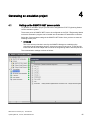
4.1
Setting up the SIMATIC NET access points .......................................................................... 65
4.2
Generating a project .............................................................................................................. 66
4.3
Options for generating the project.......................................................................................... 67
4.4
Completing generation of the project ..................................................................................... 68
4.5
Integrating and starting with SIMIT SF................................................................................... 69
4.6
4.6.1
4.6.2
4.6.3
Integrating WinCC servers ..................................................................................................... 72
Setting up the PCS 7 OS/WinCC computer with the component configurator ...................... 72
SIMATIC NET special configuration ...................................................................................... 73
Adapting the connection parameters ..................................................................................... 74
4.7
4.7.1
4.7.2
4.7.3
Integrating the emulation computer ....................................................................................... 76
Setting up the emulation computer using the component configurator ................................. 76
SIMATIC NET access points on the emulation computers .................................................... 77
Adapting the SIMATIC NET configuration on the emulation computers................................ 78
Special use cases ................................................................................................................................. 79
5.1
Update project ........................................................................................................................ 79
5.2
Subsequent engineering changes to the program logic ........................................................ 79
5.3
The following engineering changes to the process signals or the hardware
configuration........................................................................................................................... 80
5.4
Setting up FB and FC-HLL blocks for automatic replacement .............................................. 81
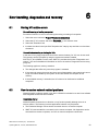
Error handling, diagnostics and recovery ............................................................................................... 83
6.1
Solving VC runtime errors ...................................................................................................... 83
6.2
How to resolve network-related problems ............................................................................. 83
6.3
Diagnostics and recovery ....................................................................................................... 84
Abbreviations ........................................................................................................................................ 89
Index .................................................................................................................................................... 91
SIMIT Virtual Controller (VC) - User Manual
4
Operating Manual, 11/2014, A5E32889042-AB
1
Start
1.1
Requirements
Scope of delivery
SIMIT Virtual Controller (VC) is an emulation platform for S7-400 controllers on MS Windows
PCs. SIMIT VC can only be used in combination with SIMIT SF .
The scope of delivery of the SIMIT VC encompasses:
● SIMIT VC software CD "SIMIT VC V3.0"
● Product information with security code through which a license key can be obtained
The software CD also includes manuals in PDF format.
Requirements for installation and operation
The SIMIT Virtual Controller (VC) V3.0 software can be installed and used with the following
operating systems and in combination with the following software:
● Operating system MS Windows 7 SP1 Professional or Ultimate, 32-bit and 64-bit
The display language of the operating system must be German or English.
● SIMIT Simulation Framework (SF) V8.1
● Process control system PCS 7 V7.0, V7.1, V8.0 and V8.1
● ESXi, V5.5 (observe the releases of any other PCS 7 system components)
● SIMATIC NET V8.2 SP2 HF4 and SIMATIC NET V12 SP2
● Virus scanner: TrendMicro
Your PC must meet the following minimum requirements:
● CD drive
● Available USB slot (do not use USB hubs)
● Minimum 1 Gbyte free memory
SIMIT Virtual Controller (VC) - User Manual
Operating Manual, 11/2014, A5E32889042-AB
5
Start
1.2 Installing the SIMIT Virtual Controller
More information is available in the Readme and in the following chapter: Installing the
SIMIT Virtual Controller (Page 6).
NOTICE
Important information:
• The simulation products of Siemens enable engineering and operation of a
plant/machine to be simulated and/or optimized. The simulation and optimization results
are solely non-binding recommendations that depend on the completeness and
correctness of the input data. The input data and the results must therefore be checked
for plausibility by the user with every simulation / optimization.
• SIMIT VC enables automation programs to be run under MS Windows. However, due to
the functional principles, limitations have to be accepted both with regard to the
availability of the system as well as the precision of the simulation (MS Windows is not a
real-time operating system, no real I/O systems and buses can be coupled).
• Even if the SIMIT VC functions were checked for the intended uses (test and training
systems), no guarantee can be given that the system can always simulate the timespecific behavior exactly and that the available substitute functions always map the
functional scope of the real controller completely.
The system is therefore not intended for controlling real plants.
The results that were determined for virtual commissioning have to be checked and
evaluated accordingly by the user.
Options for accessing documentation on SIMIT VC
You can find the SIMIT VC documentation at the following locations:
● On the SIMIT VC V3.0 CD
● Via the menu item "Help" in the Emulation Manager
The product documentation is installed with the relevant product.
Note
The statements in the Readme take precedence over all other SIMIT VC documents.
1.2
Installing the SIMIT Virtual Controller
The SIMIT Virtual Controller (VC) software has to be installed on a computer on which SIMIT
SF is also installed. The software can also be installed on additional computers. You have to
be logged on to the computer with administrator rights to install SIMIT VC.
SIMIT Virtual Controller (VC) - User Manual
6
Operating Manual, 11/2014, A5E32889042-AB
Start
1.2 Installing the SIMIT Virtual Controller
Installation
Note
Before SIMIT Virtual Controller is installed, the SIMIT SF software has to be installed in a
compatible version. The installation instructions for SIMIT SF are available in the help for
SIMIT SF at: SIMIT > Start > Installation and update".
SIMIT SF may not be executed during the installation of SIMIT VC.
If used in conjunction with SIMIT VC S7 communications connections, SIMATIC NET also
has to be installed in a version released for SIMIT VC before SIMIT VC is installed. You can
find additional information on the compatibility of the versions in the readme file.
The "Emulation Manager" software packages and the diagnostics tool "Diagnostics and
Restore" are installed.
The Setup.exe program required for installation is located on the software CD.
If the current user privileges are insufficient, an error message is displayed. The user must
have "Administrator" or at least "Power User" rights and the user login has to be protected
with a password. The User Account Control must be set to the lowest value.
If you have to carry out changes here, the operating system has to be rebooted before you
begin with the installation of SIMIT VC.
Note
If you bypass the user rights check by changing the compatibility mode of the Setup program
in "Windows XP", the result is a faulty installation of SIMIT VC.
SIMIT Virtual Controller (VC) - User Manual
Operating Manual, 11/2014, A5E32889042-AB
7
Start
1.2 Installing the SIMIT Virtual Controller
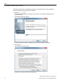
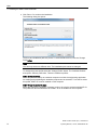
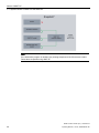
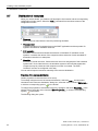
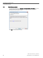
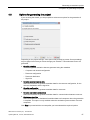
Follow the instructions in the installation program, as described below, during installation.
Internet access is not required for the installation.
● Start the Setup.exe file.
You are prompted whether the setup is to be carried out in German or English and to
confirm with "OK".
The following dialog box opens:
Close all programs you have running before you proceed with the installation.
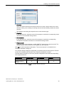
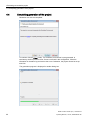
● Click "Next >".
The following dialog box opens:
Accept the conditions of the license agreement.
SIMIT Virtual Controller (VC) - User Manual
8
Operating Manual, 11/2014, A5E32889042-AB
Start
1.2 Installing the SIMIT Virtual Controller
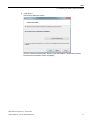
●
Click "Next >".
The following dialog box opens:
Click the "I want to read the notes" button to open the Readme. The Readme contains
important user information. Read it completely.
SIMIT Virtual Controller (VC) - User Manual
Operating Manual, 11/2014, A5E32889042-AB
9
Start
1.2 Installing the SIMIT Virtual Controller
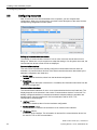
● Click "Next >" to continue the installation.
The following dialog box opens:
The drive and installation path are preset. To select a different drive, click the "Change
Drive"button.
Note
You can only select one different drive. The installation path cannot be changed.
To change the preset profile select the "Change Profile" button. The "Available Profiles"
area opens. Select a profile here. There are 2 different profiles:
SIMIT Virtual Controller
Select this profile to set up an emulation computer on which the engineering application
for creating and maintaining the emulation projects can be executed. To be able to select
this profile, SIMIT SF must be installed on this computer.
SIMIT Virtual Controller Runtime
Select this profile if the emulation computer is only to be used to execute emulated PLCs.
This profile can also be selected even if SIMIT SF is not installed on this computer.
SIMIT Virtual Controller (VC) - User Manual
10
Operating Manual, 11/2014, A5E32889042-AB
Start
1.2 Installing the SIMIT Virtual Controller
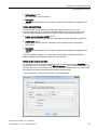
● Click the "Next >" button.
If Setup now finds a different version of SIMIT VC on the computer, a dialog box opens
with the appropriate information. An older software version then first has to be removed.
After removal is complete, setup continues automatically.
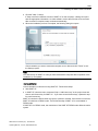
● When the installation process is complete, the following dialog box opens:
Choose whether you want to restart the computer now or later and click "Finish" to exit
the Setup program.
Note
You cannot fully run SIMIT VC until you have rebooted the computer after completion of the
installation (or an update).
License activation
License activation is carried out using SIMIT SF. Follow these steps:
● Start SIMIT SF.
● In SIMIT SF select the menu command "Help > Add license key" in the project view and
enter a valid license key for SIMIT VC . If you have several license keys, repeat this step
for each license key.
SIMIT VC checks the license when a project is opened or created. If the license is not found,
SIMIT VC switches to DEMO mode. The full functionality of SIMIT VC is not available in
DEMO mode.
If SIMIT SF is in DEMO mode, the restrictions of the SIMIT SF DEMO mode affect the entire
system.
SIMIT Virtual Controller (VC) - User Manual
Operating Manual, 11/2014, A5E32889042-AB
11
Start
1.2 Installing the SIMIT Virtual Controller
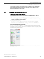
Entries in the Windows Start menu
After the installation of SIMIT VC, you can find the following entries in the Windows Start
menu:
● SIMIT Virtual Controller
– Diagnostic and Recovery
This starts diagnostics and recovery. For more information, refer to the section:
Diagnostics and recovery (Page 84).
– Emulation Manager
This is used to open the Emulation Manager. This entry is only available when the
"SIMIT Virtual Controller" profile has been installed.
– Log files
This is used to open the Windows Explorer in the directory of log files.
– Documentation
This is used to open the user manual or the reference manual. This entry is only
available when the "SIMIT Virtual Controller" profile has been installed.
SIMIT Virtual Controller (VC) - User Manual
12
Operating Manual, 11/2014, A5E32889042-AB
Basics of SIMIT VC
2.1
2
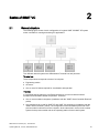
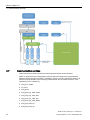
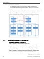
General structure
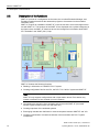
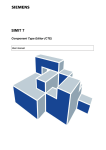
The following figure shows a basic configuration of a typical SIMIT VC/SIMIT SF system
which is suitable for running and testing S7 applications:
Two different network systems are differentiated: Terminal bus and plant bus.
Terminal bus
These components correspond to those of a real plant:
● Engineering station
● OS server
● One or more OS clients required for visualization and operation
Plant bus
It is assumed that the plant bus is an Ethernet network. It is used to interconnect all
emulation and simulation-related components. These are:
● One or more emulation computers (installation with the "SIMIT Virtual Controller Runtime"
profile)
● One computer that is used for SIMIT SF and SIMIT VC engineering (installation with the
"SIMIT Virtual Controller" profile). The configuration of the emulation system and of the
process model is carried out on this computer. At the same time it serves as the runtime
system for the process model and as the operating station for the overall system.
SIMIT Virtual Controller (VC) - User Manual
Operating Manual, 11/2014, A5E32889042-AB
13
Basics of SIMIT VC
2.2 Description of the functions
2.2
Description of the functions
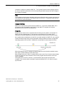
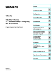
SIMIT VC consists of a configuration environment, the so-called Emulation Manager, and
Emulation Runtime that allows the automation program to be executed on the emulated
controllers (VCs).
SIMIT VC requires an installation of SIMIT SF in the version that is current and approved for
use with SIMIT VC. The functions of the SIMIT VC are displayed with a yellow background in
the figure below; the SIMIT SF functions have a blue background. Information about SIMIT
SF is available in the "SIMIT (V8.1)" Help.
SIMIT VC features the following functions:
● Reading in information of a SIMATIC PCS 7 system
● Creating configuration files for the VCs, the PCS 7 OS / WinCC system and SIMIT SF
Note
SIMIT VC only supports configurations with unique station names. Each station may
contain a maximum of one controller (or one H-system).
● Coordinating the execution of an emulation environment with SIMIT SF (command
transfer, synchronization of the VCs and SIMIT SF)
● Creating snapshots of the emulated systems
● Exchanging data that are distributed on several computers between SIMIT SF and VCs
● Creating communication connections between virtual controllers and PCS 7 system
components
SIMIT Virtual Controller (VC) - User Manual
14
Operating Manual, 11/2014, A5E32889042-AB
Basics of SIMIT VC
2.3 Supported system functions
The virtual controllers (VCs) provide the following basic functions of a controller, regardless
of the individual type:
● Downloading the application software to the virtual memory of the VCs
● Interpretation of MC7 code
● Providing data areas, arithmetic units, accumulators and results of logic operations,
counters, memory bits, timers, memory areas for the process images, etc.
● OB management and scheduling
● Start substitute implementations of system functions (SFCs, SFBs).
● Integration of plug-ins that make the cycle-independent functions available, (e.g.
communication connections)
● Command interface to control the start and stop commands, the cycle execution and the
creation of snapshots
The Emulation Runtime supplements these basic functionalities with the following functions:
● Communication functions. You can find additional information on this in the section:
Supported communications connections (Page 20).
● Access to the I/O section. You can find additional information on this in the section: Input
and output system (mapping of the field bus and its devices) (Page 24).
● Synchronization of the emulated controllers with each other. You can find additional
information on this in the section: Synchronization of the emulated control systems
(Page 25).
● Synchronization of the emulated controllers and their I/Os with the SIMIT SF simulation
system. You can find additional information on this in the section: Synchronization of
SIMIT VC with SIMIT SF (Page 26).
● Creation and storage of snapshots You can find additional information on this in the
section: Synchronization of SIMIT VC with SIMIT SF (Page 26).
2.3
Supported system functions
SIMIT VC enables automation programs to run on virtual controllers. The automation
programs may have been created for different controllers from the S7-300 and S7-400
controller ranges. Differences between the controllers (performances, memory sizes, etc.)
are not taken into consideration in the process.
Extensions that surpass the standard functionality of an S7-417-5H are not supported. This
applies, for example, for add-on functions of an AS 410-5H. SIMIT VC then uses the
functionality of an S7-400 CPU 417-5H.
SIMIT Virtual Controller (VC) - User Manual
Operating Manual, 11/2014, A5E32889042-AB
15
Basics of SIMIT VC
2.3 Supported system functions
Substitute functions in SIMIT VC
Automation programs generally contain the following components:
●
MC7 code (which can be interpreted by the VC)
● Data blocks
● Calling system functions (SFC/SFB) which graphically display access to the hardware
components of the different controllers, for example, to the user.
These components are in a different form on PC systems or not available at all.
Therefore, substitute functions are used for SFCs and SFBs in SIMIT VC in order to
achieve as much compatibility with real controllers as possible.
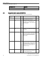
The following system functions are supported by SIMIT VC:
Type
Block number
SFB
0 - 5, 8, 9, 12 - 15, 22, 23, 31,
33 - 36
Comment
SFB
54
SFC
0
SFC
1 - 6, 13 - 15, 17 - 34, 36 - 44,
46 - 50
SFC
51
SFC
62, 64, 79, 80, 81, 85, 87, 90,
107
SFC
65090 - 65097, 65099, 65102,
65103
The VCs are always synchronized internally to the computer
time; SET_CLK therefore only
has a temporary effect
SSLs are supported to a limited
extent by the VC as no simulation of the distributed peripherals exists
SIMIT Virtual Controller (VC) - User Manual
16
Operating Manual, 11/2014, A5E32889042-AB
Basics of SIMIT VC
2.4 Handling synchronous faults
Note
• The use of SFCs is limited due to the functional principles, since the I/Os are not
simulated, for example.
• Before using SIMIT VC, check whether the SFBs and SFCs required by your automation
program are supported. To do this, compare for example the reference data of the blocks
in SIMATIC Manager. You can find more detailed information about the reference data in
the STEP 7 help.
• The substitute functions supply usable feedback signals for standard operation without
hardware faults in as far as this is possible with the implementation depth and the
information available from the SIMATIC project. Statements about the reaction to a fault
are only possible to a limited extent and have to be verified independently by the user.
• If the automation program (via an FB or FC, for example) relies on system functions for
which SIMIT VC has provided no substitute functions, these system blocks are replaced
by a NOP (No Operation). If the automation program relies on reactions of these system
functions, you can make the corresponding (instance) DB addressable in SIMIT SF and
create the required information directly in SIMIT SF. You can find additional information
on this in the section: Importing process signals (Page 63).
2.4
Handling synchronous faults
Not all synchronous faults are recognized or handled correctly by SIMIT VC (calling of a fault
OB). The fault may not be recognized, although it generates a Runtime Error (RTE).
The error handling of SIMIT VC in overview:
Description of error
Supported
BCD conversion error
Yes
Range length error during reading
No, generates RTE
Range length error during writing
No, generates RTE
Range error during reading
Yes
Range error during writing
Yes
Timer number error
No, generates RTE
Counter number error
No, generates RTE
Alignment error during reading
Yes
Alignment error during writing
Yes
Write error data block
No, writing is carried out into the read-only block
Write error instance data block
No, writing is carried out into the read-only block
Block number error DB
No, generates RTE
Block number error DI
No, generates RTE
Block number error FC
No, generates RTE
Block number error FB
No, generates RTE
DB not loaded
Yes
SIMIT Virtual Controller (VC) - User Manual
Operating Manual, 11/2014, A5E32889042-AB
17
Basics of SIMIT VC
2.5 Sequential control system of SIMIT VC
2.5
Description of error
Supported
FC not loaded
Yes
FB not loaded
No, generates RTE
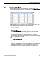
Sequential control system of SIMIT VC
SIMIT VC supports the following organization blocks of a real controller:
Supported by
SIMIT VC
Block type
Block
Description and event
1
User program
OB1
Execution of the user program after restart 1
(end of OB100) and at cycle end.
10-17
Time-of-day interrupt
OB10
Time of day and date. A trigger can be
2
initiated at a specific point in time so that a
time OB (10 - 17) is called which then
executes a program. Is also called time-ofday interrupt OB.
OB11
OB12
OB13
OB14
Priority
OB15
OB16
OB17
20-23
Time-delay interrupt
OB20
OB21
OB22
Time-delay interrupts. After a delay time,
the OB (20 - 23) is called and the program
is executed.
OB23
30-38
Cyclic interrupt
OB30
OB31
OB32
OB33
OB34
Hardware interrupt
Cyclic interrupts start periodically after a
defined period. Similar to clock signals but
much more accurate. The processing of
OB1 is interrupted because they have a
higher priority.
7
8
9
10
11
12
OB36
13
OB37
14
OB40
OB42
OB43
OB44
15
Hardware interrupts. Respond at interruptible input, output or function modules
to configured events, for example, positive
edge, high limit violation. Are used, for
example, when the response time in the
program is too long.
16
17
18
19
20
OB45
21
OB46
22
OB47
DPV1 interrupt
5
OB35
OB41
-
4
6
OB38
-
3
OB55
OB56
OB57
23
DPV1 interrupts Status, update or manufacturer-specific interrupts are triggered in
connection with DPV1 slaves.
2
SIMIT Virtual Controller (VC) - User Manual
18
Operating Manual, 11/2014, A5E32889042-AB
Basics of SIMIT VC
2.5 Sequential control system of SIMIT VC
-
Multicomputing
interrupt
OB60
Synchronous operation of several CPUs
25
-
Isochronous mode
interrupt
OB61
Configure short and equidistant process
response times at the PROFIBUS DP
25
OB62
OB63
OB64
-
Background cycle
OB90
For program execution in the background
29
100-102
Startup
OB100
After restart (warm restart) of the CPU
27
121, not 122
Synchronous errors
OB101
After restart of the CPU
OB102
After cold restart of the CPU
OB121
When a module fault occurs
29
OB122
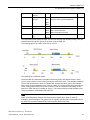
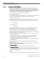
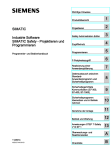
The sequential control system of SIMIT VC does not interrupt OBs already running. They are
classified according to their priority in the basic cycle of SIMIT VC .
The following figure has a basic cycle time of 100 ms:
The following time response results:
The active OBs are executed in accordance with their priority and without delays in each
cycle. A cycle violation occurs in the figure above at the value "400". The complete emulation
cycle is then increased, the token is enabled later and the next basic cycle is then started
with a delay. In the subsequent cycle, however, SIMIT VC corrects all the times internally (as
shown in the graphic above) from "400+x" back to "400" and continues calculating on this
basis even if the real time is already at "400+x". This ensures that the virtual simulation time
is kept consistent in combination with SIMIT SF .
Note
SIMIT VC distinguishes between timer times and the system time, which is used, for
example to send messages. The system time is regularly synchronized to the system time of
the SIMIT SF computer independently of the progress of the timer times.
SIMIT Virtual Controller (VC) - User Manual
Operating Manual, 11/2014, A5E32889042-AB
19
Basics of SIMIT VC
2.6 Supported communications connections
2.6
Supported communications connections
S7 controllers support various communication interfaces and protocols depending on the
type. Various communication processors (CPs) and communication functions (for example,
BSEND / BRECV) are used in the process.
Note
SIMIT VC does not support all of these communications connections. If you use
communications connections in your project other than the ones described here, you must
re-configure these to the supported connections.
SIMIT VC supports the following communications connections:
● Programming device interface for downloading the automation software and online
monitoring of the running controller. Only the TCP/IP-based Ethernet interface can be
used for this. Downloading via MPI or other interfaces is not supported.
● S7 communication of emulated controllers (VC) with real PCS 7 OS/WinCC servers or
clients.
Note
The following requirements apply to a computer on which both WinCC and a VC (single
station) should run:
• The computer must be assigned the role "Emulation/simulation" in the computer
configuration of the Emulation Manager.
• The Station Configuration Editor must be loaded with the generated xdb file of the
corresponding emulation computer (with the prefix "vc_").
• Named connections are not possible on a single station.
● Open communication of emulated controllers (VC) is based on UDP or TCP.
● Communication between emulated controllers (VC).
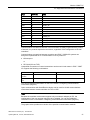
The following blocks can be used depending on the communication paths:
Type
FC/FB No.
Name
FB
12
BSEND
FB
13
BRCV
FB
14
PUT
FB
15
GET
FC
5
AG_SEND
FC
6
AG_RECV
FC
50
AG_LSEND
FC
60
AG_LRECV
SFB
8
USEND
SFB
9
URCV
SFB
12
BSEND
SFB
13
BRCV
SIMIT Virtual Controller (VC) - User Manual
20
Operating Manual, 11/2014, A5E32889042-AB
Basics of SIMIT VC
2.6 Supported communications connections
Type
FC/FB No.
Name
SFB
14
GET
SFB
15
PUT
SFB
22
STATUS
SFB
23
USTATUS
SFB
31
NOTIFY_8P
SFB
33
ALARM
SFB
34
ALARM_8
SFB
35
ALARM_8P
SFB
36
NOTIFY
SFC
17
ALARM_SQ
SFC
18
ALARM_S
SFC
19
ALARM_SC
SFC
107
ALARM_DQ
SFC
108
ALARM_D
Communications connections between virtual controllers are always implemented by means
of internal, non protocol-dependent connections, regardless of the configuration of the real
controllers.
Communications connections between controllers and PCS 7 OS/WinCC systems can
always be implemented as S7 communication via CP by means of
● ISO transport
or
● RFC1006 (ISO-on-TCP).
Unspecified connections or named connections can be used in both cases in PCS 7. SIMIT
VC supports the following combinations:
ISO transport
ISO-on-TCP
Unspecified connection
X
X
Specified connection
X
-
You can find additional information on this in the section: Configuring communications
connections (Page 53)
Open communication with Send/Receive blocks can be used for AS-AS communications
connections between virtual controllers via TCP or UDP.
Note
Because the emulation environment supports only one network adapter per PC, the
configuration of the user program may have to be adapted. You can find additional
information on this in the section: Configuring communications connections (Page 53).
The graphic below provides an overview of the possible communication methods:
SIMIT Virtual Controller (VC) - User Manual
Operating Manual, 11/2014, A5E32889042-AB
21
Basics of SIMIT VC
2.7 Communication services
2.7
Communication services
Actual controllers provide extensive services that permit access to the controller.
SIMIT VC supports a few communication services which are required for communication
between virtual controllers and PCS 7 OS/WinCC servers or PCS 7 OS/WinCC clients. The
services provide answers to the following requests which can be placed via the S7_DOS
interface by PCS 7 OS/WinCC:
● s7ag_brcv_create
● s7_event
● s7ag_bsnd
● s7ag_bub_cycl_read_create
● s7ag_bub_cycl_read_start
● s7ag_bub_cycl_read_stop
● s7ag_bub_cycl_read_delete
● s7ag_bub_read_var
● s7ag_bub_write_var
SIMIT Virtual Controller (VC) - User Manual
22
Operating Manual, 11/2014, A5E32889042-AB
Basics of SIMIT VC
2.7 Communication services
● s7ag_pmc_msg_mode
● s7ag_pmc_msg_on_off
● s7ag_pmc_msg_ack
● s7ag_pmc_update
● s7ag_read_szl
● s7l7_dataexchange2
● s7ag_bub_read_var
● s7ag_bub_write_var
This means the following services used by PCS 7 OS / WinCC are available on the
emulation side:
● VFD / Virtual Device Services
– Read SCL (whereby the scope of SSL IDs is only implemented to the extent required
to support PCS 7 OS/WinCC communication)
● OCM services
– Cyclic Read variables (Start, Stop, Change, Abort, Delete)
– Read variables
– Write variables
● Message services
– Acknowledge
– Announcement for messages (not SCAN, LT group message and archives)
– Lock / Unlock messages (not SCAN, LT group message and archives)
– Message update (not SCAN, LT group message and archives)
● PBK services
– USEND / URCV
– BSEND / BRCV
– PUT (write variables)
– GET (read variables)
Note
Other requests are not answered by the virtual controller. Therefore systems that require
further services cannot communicate correctly with the emulated controllers. These include
for example:
• Route Control
• BRAUMAT Classic
• AS based Batch
SIMIT Virtual Controller (VC) - User Manual
Operating Manual, 11/2014, A5E32889042-AB
23
Basics of SIMIT VC
2.8 Communication with PCS 7 OS/WinCC via SIMATIC NET
2.8
Communication with PCS 7 OS/WinCC via SIMATIC NET
Communication via S7 communication services is implemented with an instance of SIMATIC
NET.
Because several instances of VCs communicate on one computer using the same SIMATIC
NET instance, the following points have to be observed during the configuration and
operation of SIMIT VC and the communication interface:
● The maximum number of send jobs that can be transmitted via SIMATIC NET is limited
by the performance of the computer and the network adapter used.
● If the communication with SIMATIC NET is too slow, data may be lost. If requests of the
PCS 7 OS/WinCC system do not receive a response from SIMIT VC, the connection is
terminated and re-established. The lost data is not sent again, because stable operation
is not possible otherwise.
● A message about the data loss is displayed in the diagnostic window. If such a message
occurs more than once (during startup, for example), the cause is most likely an overload;
it should be eliminated by suitable measures such as the distribution of VCs to several
computers and therefore several instances of SIMATIC NET.
● The connection parameters for ISO transport connections are to be changed on the PCS
7 OS/WinCC side per controller in such a way that a unique assignment of the
connections between PCS 7 OS/WinCC and the controllers is possible via MAC address
and TSAP.
In the case of systems with real controllers this unique assignment is already
implemented via the MAC address.
● Multiple VCs can run on one PC. The connection parameters on the PCS 7 OS/WinCC
side must therefore be adjusted in such a way that the MAC address of the PC network
card is entered for all VCs. The unique assignment is implemented via the manual
allocation of TSAPs composed of the rack and slot number of the connection
configuration.
You can find additional information on this in the chapter: Configuring communications
connections (Page 53).
2.9
Input and output system (mapping of the field bus and its devices)
SIMIT VC exchanges the area of the PIO/PII (process image outputs and inputs) of all virtual
controllers cyclically with SIMIT SF. The bus systems in the configuration of the plant, such
as
● PROFIBUS DP
● Profinet IO
● Modbus
● FF
SIMIT Virtual Controller (VC) - User Manual
24
Operating Manual, 11/2014, A5E32889042-AB
Basics of SIMIT VC
2.9 Input and output system (mapping of the field bus and its devices)
are not simulated. This means functions which depend on the actual presence of
communication processors and/or field devices cannot be used directly. This includes, for
example, information that is exchanged with nodes on the bus using the following system
functions:
● WR_REC(SFC 58)
● RD_REC(SFC 59)
● WRREC(SFB 53)
● RDREC (SFB 52)
● RDSYSST (SFC 51)
In these cases, you must use a substitute function. For more information, refer to the
section: Supported system functions (Page 15).
Note
When a hardware configuration is imported, I/O areas that are cyclically exchanged between
a controller and I/O devices are first created as byte signals. When importing a symbol table,
for example, the symbolic signal names can also be read in order to use them in SIMIT SF.
You can find additional information on this in the section: Importing resources (Page 39).
To transfer data to SIMIT SF that are not exchanged via this I/O area, follow these steps:
• Replace the block that implements the appropriate communication with an NOP
and
• Enter the required signals from the instance data blocks in the VC coupling.
This applies, for example, to data that is exchanged between controllers and I/O devices via
the above-mentioned system functions.
You can find additional information on this in the manual "SIMIT Virtual Controller (VC) Reference Manual" under:
• Menu command "Project" > HLL functions"
• Menu command "Project > Signal list"
2.10
Synchronization of the emulated control systems
In order for emulation to run continuously, all VCs are synchronized. SIMIT VC establishes a
so-called token ring for each participating computer (in the following example, two computers
with two cores each) through which the individual VCs (in our example, a total of eight) are
triggered. The token passes through the following stations one after the other:
● Control Process
The control process implements the interface to SIMIT SF to perform the commands
"Start", "Stop", "Freeze", "Run", etc.
● Signal mirroring
This process mirrors the interface data between all participating computers, reads the
data of the virtual controller coupling and copies the results of the last emulation cycle to
SIMIT Virtual Controller (VC) - User Manual
Operating Manual, 11/2014, A5E32889042-AB
25
Basics of SIMIT VC
2.11 Synchronization of SIMIT VC with SIMIT SF
the virtual controller coupling. The synchronization of the data exchange and the
synchronization via the Proceed command of SIMIT SF depend on the signal process.
● VCs
The token is divided: One token is made available for each available CPU core. The VCs
now compete for the assignment of the tokens until all have been calculated once via the
Windows operating system functions. The tokens are then combined by the control
process and the next cycle can begin.
2.11
Synchronization of SIMIT VC with SIMIT SF
Data exchange between SIMIT SF and SIMIT VC
SIMIT VC and SIMIT SF map two aspects of a technical plant:
● SIMIT VC simulates the automation systems (controllers) including process image of
inputs and outputs (without mapping the field level)
● SIMIT SF simulates the process image of the plant in the form of physical or data values.
Even though field devices can be mapped in their functionality, they are not displayed
directly in the simulation.
SIMIT VC and SIMIT SF exchange this process data through a shared data memory that is
created by SIMIT VC and connecting to SIMIT SF via a coupling when simulation is started.
Configuration of the interface is carried out in the Emulation Manager. The "Virtual
SIMIT Virtual Controller (VC) - User Manual
26
Operating Manual, 11/2014, A5E32889042-AB
Basics of SIMIT VC
2.11 Synchronization of SIMIT VC with SIMIT SF
Controller" coupling is created in SIMIT SF . The "Update" function of the coupling can then
be used to import the information of the corresponding emulation project and thus configure
the coupling completely.
Note
The emulation project and the simulation project are defined through a project name that has
to be identical in both systems. This project name can be up to 17 characters long and may
not include any special characters.
Command interface
SIMIT VC is controlled and synchronized by SIMIT SF . If you have installed SIMIT VC in
accordance with the installation instructions on the SIMIT SF computer, all required
parameters and services are already preset.
Snapshots
Snapshots are used to save a complete state of training or test systems, for example, for
future use as the starting state. To this purpose, the snapshot has to contain all the
information so that the state that was active at the time of storing can be restored exactly.
Also systems that are addressed via the RCI command interface of SIMIT SF, can create an
overall consistent image of the current simulation state provided this function is supported.
Operating systems such as PCS 7 OS/WinCC are excluded from the snapshot function.
When the snapshot "X(t1)" is loaded, all internal states are set so that the emulation at the
time "X(t3)" is placed exactly on the state "X(t1)".
When loaded at the time "X(t3)", a snapshot stored at the time "X(t1)" has the internal states
of the VCs required for the execution of the control program that were active at the time
"X(t1)" as default.
The system time of the VC, however, is synchronized to the current time of the host
computer. This ensures that the emulation system and HMI (PCS 7 OS / WinCC) remain
synchronized.
SIMIT Virtual Controller (VC) - User Manual
Operating Manual, 11/2014, A5E32889042-AB
27
Basics of SIMIT VC
2.11 Synchronization of SIMIT VC with SIMIT SF
Note
If the automation program is reloaded, any existing snapshots of the VCs become invalid.
Delete these snapshots using SIMIT SF.
SIMIT Virtual Controller (VC) - User Manual
28
Operating Manual, 11/2014, A5E32889042-AB
Creating a new emulation project
3.1
3
Requirements
The following requirements must be met to set up a new emulation project:
● SIMIT VC and SIMIT SF are installed.
● A PCS 7 project is created and set up.
● To be able to load the automation program, the PCS 7 engineering station has access to
the emulation computer.
● A PCS 7 hardware configuration file (*.cfg) has been exported.
For additional information about the PCS 7 data export, see section: Exporting PCS 7
engineering data (Page 29)
With this data, you can create a new project with some VCs and corresponding I/O signals.
You should have a list with all the PCs that you want to integrate into the emulation platform.
This list should also include the IP addresses and the MAC addresses (physical addresses
of the network adapter) of the PCs .
3.2
Exporting PCS 7 engineering data
3.2.1
Exporting hardware configuration files
Proceed as follows to export hardware configuration files from PCS 7:
● Start SIMATIC Manager.
● Open the project to be used for the emulation.
● Start NetPro. You can export several stations simultaneously in Netpro.
● Select the menu command Edit > Export….
SIMIT Virtual Controller (VC) - User Manual
Operating Manual, 11/2014, A5E32889042-AB
29
Creating a new emulation project
3.2 Exporting PCS 7 engineering data
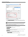
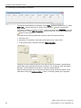
● Please select all stations for export you want to emulate.
● Under Default path for export files, select a suitable storage location for the transfer of
the export file to SIMIT VC. For example, this can be a common network drive or a USB
stick.
Note
The reference file is based on local absolute path information. A reference file cannot be
imported if the Emulation Manager accesses both–the reference file and the exported
hardware configuration files – via a network share.
Select the check box of the dialog box as shown in the figure above:
● Export default values
This is used to export the OB time values.
● Export symbols
This is used to export the symbols. If you have assigned symbols to I/O signals, they are
displayed in the signal list of the emulation project.
● Export subnets
This is used to include signals of I/O modules into the signal list which are related to
subnets, provided you have assigned symbols to I/O signals.
– Export S7 connections
This option does not have any effect on the emulation project.
SIMIT Virtual Controller (VC) - User Manual
30
Operating Manual, 11/2014, A5E32889042-AB
Creating a new emulation project
3.2 Exporting PCS 7 engineering data
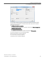
● Apply options and format to all stations
This applies the options and the format to all selected stations.
● Readable
This is used to export the readable format of the file. The Emulation Manager can only
read this format.
Click OK to apply your settings and carry out the export.
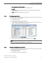
3.2.2
Exporting a symbol table
If you want to import process signals into the emulation via symbol tables, you have to export
the symbol table. Follow these steps:
● Start SIMATIC Manager.
● Open the project to be used for the emulation.
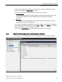
● In the component view, navigate to the "Symbol" object in the station for which you want
to export a symbol table and double-click to open it:
● Select the menu command Table > Export....
● Select the type and storage location for the symbol table and click Save.
Note
SIMIT VC can only import files of the type *.seq, *.dif and *.sdf.
3.2.3
Creating and exporting an STL Source
If you want to import process signals into the emulation via STL sources, you have to create
and export an STL source. Follow these steps:
● Start SIMATIC Manager.
● Open the project to be used for the emulation.
SIMIT Virtual Controller (VC) - User Manual
Operating Manual, 11/2014, A5E32889042-AB
31
Creating a new emulation project
3.2 Exporting PCS 7 engineering data
● Double-click on any program block.
The LAD/STL/FBD program block editor opens.
● Select the menu command File > Generate source….
The "New" dialog box opens.
● Select an existing source or enter a new object name to create a new source element.
● Click OK.
The "Generate source <name>" dialog box opens.
● Here you select all the data blocks you want to export. If one of the data blocks
references a UDT, you have to select it as well.
● Click OK to generate the source element.
● Switch to the component view.
● Navigate to the "Sources" folder in the project hierarchy.
The generated source element is now in the right-hand window.
● Click the generated source element and select Export source... in the shortcut menu.
● Select the storage location of the exported file. *.awl has to be selected as the file type.
SIMIT Virtual Controller (VC) - User Manual
32
Operating Manual, 11/2014, A5E32889042-AB
Creating a new emulation project
3.3 Using wizards
3.3
Using wizards
Wizards facilitate the use of SIMIT VC by guiding the user through the function step-by-step.
The following section briefly describes the use of wizards.
The dialog window of the wizard contains a description of what needs to be done during the
current step or prompts you to input values related to the respective step.
● Click "Next" to proceed with the next step after you have entered all the required values.
● Click "Back" to go back one step. Going back might not be available in all cases.
● The "Finish" button is available at the end of the wizard or when it is possible to shorten a
procedure by skipping further (optional) actions. Clicking this button will perform all the
actions you have prepared during the various steps.
● Use the "Cancel" button if you wish to cancel the wizard.
Canceling a wizard
Any attempt to cancel a wizard requires a confirmation.
● Click the "Yes" button to cancel the wizard.
● Click the "No" button to not cancel the wizard.
● Click the "Continue later" button to mark the actual configuration sequence to be
continued at a later time.
You may continue a canceled wizard by clicking Project > Continue action... in the menu
bar.
SIMIT Virtual Controller (VC) - User Manual
Operating Manual, 11/2014, A5E32889042-AB
33
Creating a new emulation project
3.4 Creating a new project
Continuing a canceled wizard
Whenever you open a project by selecting a wizard to continue or selecting a wizard for
continuing manually, you will be prompted to continue the appropriate action.
● Click the "Yes" button to continue the canceled action.
● Click "No" if you do not want to continue the action. The action remains marked for
continuation.
● If you do not want to continue the action, click "Do not continue".
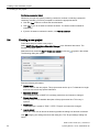
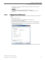
3.4
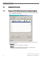
Creating a new project
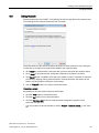
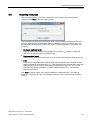
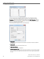
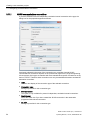
Follow these steps to create a new project:
Select SIMIT Virtual Controller > Emulation Manager in the Windows Start menu. The
Emulation Manager opens.
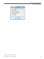
Select the menu command Start > Create new project or click the " " symbol in the toolbar.
The following dialog box opens:
Enter the following information:
● Project name
Enter a name for the new project. This project name can be up to 17 characters in length
and must not include any special characters.
● Emulation directory
The installation folder of SIMIT VC is already preset here and cannot be changed.
● Project description
You may enter a more detailed description of the project name here. This entry is
optional.
● Project type
The project type is preset to "PCS 7 / STEP 7 Project" and cannot be changed.
● Launch wizard
Select this check box to launch the wizard right after the dialog box has been confirmed.
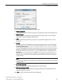
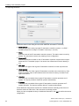
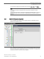
Click OK to apply your settings and close the dialog box. The "Project settings" dialog box
opens:
SIMIT Virtual Controller (VC) - User Manual
34
Operating Manual, 11/2014, A5E32889042-AB
Creating a new emulation project
3.4 Creating a new project
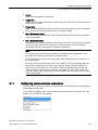
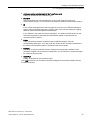
You can make the following settings in this dialog box:
● Project description
The project type from the previous dialog box is displayed and can still be changed here.
● Cycle time (ms)
Set the cycle time in milliseconds for emulation of the current project. This is the time it
would take to compute a single emulation cycle.
● Time
Here you select the time basis for the project. You can select "System time" or "Local
time" here.
● License
The existing license is displayed here. Click the 'magnifying glass' to have the available
licenses displayed. There you select the SIMIT SF license for which one or more SIMIT
VC licenses are installed.
Click the magnifying glass symbol to view available licenses. You can search for licenses
globally in the network or limit the search to the computer defined in the project. Select
. The available licenses are displayed in the
the required function with the symbols
dialog box.
The restriction to computers that are configured in the project is only relevant if you, for
example, open or retrieve an existing project and several SIMIT licenses are accessible
in your network.
Note
If no license is available or if the number of licensed VCs is too small, SIMIT VC switches
to DEMO mode.
● No consistency check
Select this check box to globally deactivate the consistency check.
● Restore consistency check
Select this check box to reactivate the consistency checks that were deactivated in the
individual configuration steps.
Click OK to confirm your settings and close the dialog box.
SIMIT Virtual Controller (VC) - User Manual
Operating Manual, 11/2014, A5E32889042-AB
35
Creating a new emulation project
3.5 Configuring the computer
The new project is now loaded and the wizard for guiding you through the process of setting
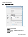
up the new project opens. Click Next to begin with the first step.
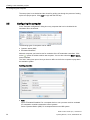
3.5
Configuring the computer
In the "Computer configuration" dialog box every computer that is to be included in the
simulation has to be entered.
The following types of computers can be added:
● Operator station (HMI)
● Emulation/Simulation
Add each computer you intend to use for emulation of the S7 automation controllers. Click
on the " " symbol in toolbar to add a new computer. You can also select the Edit > Insert...
menu command.
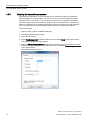
The "Add.." dialog box opens. Here you have to define a role for the computer to play within
the emulation system.
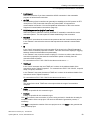
Inputting properties
● Role
Select "Emulation/Simulation" for a computer that is to run a process model or emulated
S7 automation controllers automation control systems.
Select "Operator Station (HMI)" for a computer that runs an HMI system.
SIMIT Virtual Controller (VC) - User Manual
36
Operating Manual, 11/2014, A5E32889042-AB
Creating a new emulation project
3.5 Configuring the computer
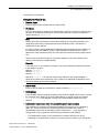
The dialog box is extended.
Settings for the "General" tab:
● Machine Name
Enter the name of the computer that you want to add.
● IP address
From the drop-down list, select the IP address that is used to connect the computer to the
plant bus. If the desired IP address is not in the drop-down list, enter the IP address in
regular format (e.g. 192.168.1.1).
Note
Always select the main address of the network adapter here. System information (e.g.
diagnostics information) is transferred and communication to PCS 7 OS/WinCC is
established via this address.
For each computer, define additional IP addresses that are identical to the IP address of
the controller from the SIMATIC project. These additional IP addresses are used to
address the online interfaces of the VCs and perform the download of the program to the
VCs.
Always enter the lowest IP address of a network adapter as the main address in the
settings of the Windows network adapter.
Example:
3 VCs are to run on an emulation computer. They have IP addresses defined as follows
in the SIMATIC project:
Station1: 192.168.0.1
Station2: 192.168.0.2
Station3: 192.168.0.3
Now enter 192.167.0.1, for example, as the main address of the network adapter in
Windows and enter the IP addresses of the 3 stations as additional IP addresses in the
advanced settings of the network adapter.
● Subnet mask
Enter the subnet mask of the interface in regular format (e.g. 255.255.255.0).
● MAC address
Enter the MAC address (physical address) of the Ethernet adapter that is used to connect
the computer to the plant bus. Enter the MAC address in regular format (for example
00.11.22.AB.CD.EF). This interface is used for S7 communication based on the ISO
protocol.
● Identification Number (only if the "Emulation/Simulation" role is selected)
This parameter is important for Emulation/Simulation PCs that are to be controlled by
SIMIT SF . When you add a new Emulation/Simulation computer the number is
automatically preset with an ascending number starting with "1". If you change the
configuration of your project later, the following conditions must be fulfilled:
– The identification number is only important for computers which are in use for
emulating an S7 automation controller or running a process model. If you change the
SIMIT Virtual Controller (VC) - User Manual
Operating Manual, 11/2014, A5E32889042-AB
37
Creating a new emulation project
3.5 Configuring the computer
resource distribution later and a computer is no longer involved in the emulation, this
computer must have a identification number outside the range of used numbers.
– The lowest identification number in use must be "1".
– The identification numbers of the used computers must be assigned in ascending
order without gap.
Note
The simulation commands cannot be processed correctly with inconsistent
Identification Numbers.
Settings for the "Network Share" tab:
● Domain
Enter the domain name of the computer if it is a member of a domain. Otherwise leave
the box empty. If you are going to use only one single emulation computer and it is
already the current computer, you can also leave the field empty. Otherwise, this
information is required for accessing the remote computer for distribution of the project
configuration files.
● User
Enter the user name related to the network share you are going to use for distribution of
the project configuration files. If you are going to use only one single emulation computer
and it is already the current computer, you can leave the field empty.
● Store password
Enable this option if the network share you are going to use for distribution of the project
configuration files is protected by a password. If you are going to use only one single
emulation computer and it is already the current computer, you can leave the option
disabled.
● Password
Enter the password which has been used to protect the network share you are going to
use for distribution of the project configuration files. This field is available only if the option
Store password has been enabled.
● Network share
Select the network share you want to use for distribution of project configuration files from
the drop-down list. If the desired network share is not part of the suggested list then you
probably do have some sort of authentication problem. Check Domain, User name and
Password for correct values and try again.
Click OK to confirm the entered information. The emulation computer is then added to the
computer configuration window.
Proceed as described above when you add additional required PCS 7 OS/WinCC server
computers.
When using the wizard click Next to proceed with the next step.
SIMIT Virtual Controller (VC) - User Manual
38
Operating Manual, 11/2014, A5E32889042-AB
Creating a new emulation project
3.6 Importing resources
3.6
Importing resources
When using the wizard, you receive a short description of how to import the required
resources. Click Next to start the import process.
The import process starts with requesting at least a single hardware configuration file which
has been exported from an appropriate SIMATIC Manager project in a previous step. You
can find additional information on this in the section: Exporting hardware configuration files
(Page 29)
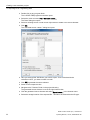
● Hardware configuration file
Enter the path to the hardware configuration file or click the " " symbol to locate and
select one or more hardware configuration files.
● Suppress signal import
Select this check box if the signals are not to be read from the hardware configuration file.
● Filter
Enter regular expressions here to appropriately filter the signal import. Separate multiple
regular expressions with semicolons (";"). These signals are then not imported. Leave the
field empty if you do not want to exclude any signals from the signal list. You can find
information on regular expressions in "SIMIT Virtual Controller (VC) - User manual >
Regular expressions".
Click Next to start the import of the selected hardware configuration files. The following
dialog box is displayed for each S7 automation controller resource that is found during the
import:
SIMIT Virtual Controller (VC) - User Manual
Operating Manual, 11/2014, A5E32889042-AB
39
Creating a new emulation project
3.6 Importing resources
Check the values in this dialog box and enter additional information if necessary.
● Resource type
Select the type of the newly imported S7 automation controller resource. In a PCS 7
emulation project this is always S7 SoftPLC resource (i.e. one VC).
● Name
Enter the name of the S7 automation controller resource. The station name is used by
default. This name does not have any meaning for the configuration.
● Resource ID
Enter an identification number for this S7 automation controller resource that is unique
within this PCS 7 emulation project. You cannot use a Resources ID that is already in
use.
● CPU type
Select the CPU type of the original S7 automation controller from the drop-down list.
● Clock memory
Select this check box if the original S7 automation controller uses clock memory. If the
option is available, enter a valid address where the timer bit memory is located in the
right-hand text box.
● H-system
This check box is available if the original S7 automation controller represents an Hsystem. The import procedure detects H-systems automatically.
● F-system
This check box is available if the original S7 automation controller represents an Fsystem (fail-safe). The import procedure detects F-systems automatically.
Some additional configuration elements are available which are already preset. Some of
these are written at a later time, if the resources are already present.
When you have completed the entry of additional information, click OK to confirm the current
configuration.
SIMIT Virtual Controller (VC) - User Manual
40
Operating Manual, 11/2014, A5E32889042-AB
Creating a new emulation project
3.6 Importing resources
New CPU modules or new I/O modules may be detected during the import. A dialog box
then opens in which you check the detected modules and add further information if
necessary.
Note
We strongly recommended that you do not cancel the configuration of newly detected CPU
and I/O modules. This would leave the CPU and I/O modules unconfigured, leading to
unexpected behavior of the PCS 7 hardware import functionality.
If the "Suppress signal import" check box is not selected and no filter is entered, the entire
I/O range of the detected I/O modules is created. In principle, you can accept the default
settings proposed during the import in the dialogs for the module settings. The import is
performed with default values.
Rules for the hardware configuration import
• First, all I/O signals of the respective resource are deleted, as long as the "Suppress
signal import" check box is cleared.
• CPU modules that were not automatically detected must be created manually. To do this,
select the "In use" check box and select the type "CPU unit" from the drop-down list.
Otherwise, no emulation resource is created and the I/O signals cannot be imported.
• CP modules that were not automatically detected must be created manually. To do this,
select the "In use" check box and select the type "Communication processor (CP)" from
the drop-down list. Otherwise, no logical device addresses (LAddr) can be read, although
they are required for communications connections.
• For I/O modules for which no type was selected, or for which the "In use" check box is not
selected, byte signals are automatically created with generic names.
• Symbols are imported only if the following conditions are met:
– The "In use" check box is selected for the module in question
– The type of module is specified
– It is a digital or an analog module for which a "Fixed sensor type" is set
• The following rules apply to the import of scaling information for analog modules:
– The selection of the sensor type specifies the bit width of the signals fixed to 16 bits.
Therefore, a fixed sensor type can be selected only for I/O modules which have a
continuous signal width of 16 bits.
– The selected sensor type must be available in the basic settings and the project
configuration. The "In use" check box must be selected in the "Sensor types" table
view. Otherwise the "Prescaled Integer" value is used for scaling.
– The configured sensor type or "Prescaled Integer" is used in the import when
- No channel-specific sensor type can be determined from the hardware configuration
- The channel-specific sensor type does not exist in the project configuration
- The "In use" check box is not selected for the channel-specific sensor type in the
project configuration.
• Automatically created signals are updated automatically when you import a symbol table
or during a CSV import of the signal list. Overlapping signals are removed and the data
width of the signals is adapted as required.
Therefore, always perform a corresponding symbol import after a hardware import.
SIMIT Virtual Controller (VC) - User Manual
Operating Manual, 11/2014, A5E32889042-AB
41
Creating a new emulation project
3.7 Distribution of resources
3.7
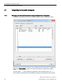
Distribution of resources
When you use the wizard, you obtain a brief description of this action and the corresponding
configuration window opens. Select the "Add..." command from the shortcut menu of the
configuration window.
● Resource
All the resources listed here are used for performing emulation.
● Process model
Contains the names of computers that run the SIMIT applications and that provide I/O
signals to simulated or emulated resources.
● PLC emulation
Emulation of resources that initiates the execution of emulated S7 emulation control
systems. It contains the names of the computers where execution of each emulated S7
automation controller is to take place.
● Execution
Execution of virtual resources. Virtual resources are not an integral part of the emulation
system itself. Via a virtual resource, the emulation system is informed that a particular
component may be present and the computer on which it is located. The PCS 7
OS/WinCC servers are configured in this way.
You can add all required resources manually to the resource distribution.
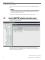
Properties of the resource distribution
Certain properties of resources have to be set up.
To manually add resources to the resource distribution, select the Add… shortcut menu
command in the "Resource distribution" dialog box, select the menu command Edit > Add…,
or click the corresponding symbol ( ) in the toolbar.
To change the properties of a distributed resource, highlight it and select Properties... in the
shortcut menu, select the menu command Edit > Properties…, or click the corresponding
symbol ( ) in the toolbar.
The following dialog box opens:
SIMIT Virtual Controller (VC) - User Manual
42
Operating Manual, 11/2014, A5E32889042-AB
Creating a new emulation project
3.7 Distribution of resources
● Resource
Select the desired resource from the drop-down list or enter a unique name for a virtual
resource. When you are editing an existing resource this field already contains the actual
resource.
The settings in this dialog box depend on the current resource type.
● Execution
In the drop-down list, select the name of the computer on which the corresponding virtual
resource is to be executed during runtime.
● PLC emulation
In the drop-down list, select the name of the computer on which the corresponding
emulated S7 automation controller is to be executed during runtime.
● Process model
Select the name of the computer on which SIMIT SF should run the process model. The
current resource will then receive its I/O signals from this computer.
Click OK to confirm the entered information. The current resource is now added in the
"Resource distribution" dialog box.
You can also directly modify the configuration of imported resources with regard to Process
model, PLC emulation and Execution in the "Resource distribution" window.
The table below provides an overview of possible configurations and distribution depending
on the type of resource.
Resource type
Process model
PLC emulation
Execution
S7 Emulation
X
X
-
WinCC or other resources
X
-
X
When using the wizard click Next to proceed with the next step.
SIMIT Virtual Controller (VC) - User Manual
Operating Manual, 11/2014, A5E32889042-AB
43
Creating a new emulation project
3.8 Configuring resources
3.8
Configuring resources
After all resources have been distributed to the computers, you can complete their
configuration. When you use the wizard, you obtain a brief description of the action and the
corresponding configuration window opens.
Setting up the communications devices
The settings of communications devices of one or more resources are carried out in this
dialog box. Select one or more resources to adapt the settings. If an H-system was used, the
communications devices of both CPUs are displayed.
Communications devices:
This area serves represents the actually configured communications devices within an
emulation. All communications devices of the actual controller that were determined by the
hardware configuration are listed here.
● Device name
columnName of the device, taken from the hardware configuration
● Description
columnGeneral description of the device. If available, this information was taken from the
hardware configuration.
Communications interfaces
The communication interfaces of one or more communications devices are listed here. The
display depends on the selection in the section "Communications devices" on the left. The
actually configured interfaces in networks and network adapters within the emulation are
displayed here. Only the interfaces for ISO communication and for UDP / TCP
communication are displayed.
● Interface column
Name of the interface, taken from the hardware configuration
● Online interface column
This check box is selected if the interface is to be used as online interface.
● IP address column
IP address of the interface. This information is relevant if the communication device is to
be used for TCP or UDP communication.
SIMIT Virtual Controller (VC) - User Manual
44
Operating Manual, 11/2014, A5E32889042-AB
Creating a new emulation project
3.8 Configuring resources
● MAC address column
The MAC address of the interface.
● Description
columnGeneral description of the interface, taken from the hardware configuration if it
exists.
Device address bindings
This tab lists the device addresses and the linked access points of one or more
communications devices in accordance with the selection in the left-hand section. The
actually configured device addresses on SIMATIC NET access points are displayed.
● Logical device address (LADDR) column
Logical device address of the interface in accordance with the hardware configuration
● Access point column
Configurable access point for the emulation of the interface within the emulation
environment
● Description
columnGeneral description of the interface, taken from the hardware configuration if it
exists.
A generic emulation adapter, a corresponding communication interface and a device
address binding are automatically created for each resource.
Setting up the resource properties
To change the resource properties select one or more elements and select Properties… in
the shortcut menu. You can also use the Edit > Properties… menu command or click the " "
symbol in the toolbar. The resource configuration supports multiple editing. This means that
the properties of several elements can be changed simultaneously.
The most important configuration elements are described below:
SIMIT Virtual Controller (VC) - User Manual
Operating Manual, 11/2014, A5E32889042-AB
45
Creating a new emulation project
3.8 Configuring resources
● Resource type
The resource type is specified here. The following settings are possible:
– S7 SoftPLC resource
Emulation of a real S7
– Runtime component
Placeholder for a component or a system that is required during the emulation
runtime, for example HMI or PCS 7 OS/WinCC.
● Name
Name of the resource, can be edited. Is taken from the hardware configuration and is
used within the configuration to represent the resource.
"General" tab
● Resource ID
A resource ID is defined here that identifies the resource uniquely during configuration
and runtime.
● Station
Name of the station, taken from the hardware configuration.
● CPU type
Type of the CPU. Taken from the hardware configuration on the basis of the MLFB
number.
● CPU
Name of the CPU, taken from the hardware configuration.
● MLFB
The MLFB number is taken from the hardware configuration and cannot be changed. If
an MLFB number was entered manually, this field remains empty.
● Clock memory
Select this check box if you wish to use clock memories. When the check box is selected,
a clock memory byte can be specified in the right-hand input box.
● H-system
Select this check box if you want to emulate the CPU as an H-system. Taken from the
hardware configuration. Only one CPU is emulated, regardless of this setting.
● F-system
Select this check box if you want to emulate the CPU as an F-system. Taken from the
hardware configuration.
"Emulation" tab
● Snapshot size
Expected size for snapshots; default is 5 MB. Values that are too small result in an error
during storage and loading of snapshots.
SIMIT Virtual Controller (VC) - User Manual
46
Operating Manual, 11/2014, A5E32889042-AB
Creating a new emulation project
3.8 Configuring resources
"Online settings" tab
● Activate engineering mode (online mode)
Select this check box if the online interface is to be permanently active.
Note
A permanently activated online interface can reduce the emulation performance.
● Security level
The security level of an F-CPU, taken from the hardware configuration. This value has to
match the configuration.
"Special properties" tab
The special properties are internal SIMIT VC settings. These settings should only be
changed in agreement with Product Support.
Adding / changing communications devices
The values displayed here are taken from the hardware configuration.
● Device name
Name of the device, can be edited.
● Rack, slot
Rack and slot of the device, taken from the hardware configuration. A change in these
values can result in the devices not being recognized when a new hardware configuration
is imported and thus not being updated. If a generic emulation adapter is used, these
values cannot be changed.
● Description
Text that can be edited freely
Adding / changing communication interfaces
The values displayed here are taken from the hardware configuration.
● Interface
Name of the interface, can be edited.
● Online interface
If this check box is selected, the interface is used as a PG interface. Depending on the
resource only one interface each can be used as a PG interface. The generic emulation
adapter may not be used as a PG interface except if only one VC is to run per computer.
● Apply IP address of host computer
This function is only available for the communication interface of the generic emulation
adapter.
● IP address
IP address of the interface, can be edited. This function is only available, if the "Apply IP
address of host computer" check box has been selected.
● Subnet mask
Subnet mask of the interface, can be edited.
SIMIT Virtual Controller (VC) - User Manual
Operating Manual, 11/2014, A5E32889042-AB
47
Creating a new emulation project
3.9 Importing HLL Blocks
● Apply MAC address of host computer
This function is only available for the communication interface of the generic emulation
adapter.
● MAC address
MAC address of the interface, can be edited. This function is only available, if the "Apply
MAC address of host computer" check box has been selected.
● Subslot
Subslot of the device. This selection is not available for the communication interface of
the generic emulation adapter.
Note
If you change this value, the interface cannot be recognized during the import of a new
hardware configuration and cannot be updated.
● Description
Text that can be edited freely
Adding / changing a device address binding
The values displayed here are taken from the hardware configuration.
● Logical device address (LADDR)
Logical device address of the interface in decimal representation
● Access point (SIMATIC NET)
Binding of the device address with an access point in SIMATIC NET. The access point
has to be configured on the computer on which the resource is to run. This value is
optional.
● Description
Text that can be edited freely
3.9
Importing HLL Blocks
The project requires configuration of High Level Language (HLL) blocks. The emulation
manager has a standard set of HLL blocks. The blocks are contained in the basic settings
and need to be imported into the project.
Note
A specific group of HLL blocks are always replaced and therefore do not appear in the
configuration window.
FBs are not automatically marked for replacement, even if the corresponding functional area
was selected for import. These blocks must be separately selected for replacement.
Otherwise, they may be accidentally replaced by a block with completely different
functionality.
SIMIT Virtual Controller (VC) - User Manual
48
Operating Manual, 11/2014, A5E32889042-AB
Creating a new emulation project
3.9 Importing HLL Blocks
SIMIT Virtual Controller (VC) - User Manual
Operating Manual, 11/2014, A5E32889042-AB
49
Creating a new emulation project
3.9 Importing HLL Blocks
When using the wizard the actual step already prompts you for the import of HLL blocks.
● Resource ID
Select the resource ID of the emulated S7 automation controller for which you want to
perform the import. When using the wizard you should select "For all" to import the HLL
configuration for all existing emulated S7 automation controllers.
● Use functional area
All HLL blocks are grouped into functional areas. You can select a functional area to use
the respective HLL blocks in your project. Some functional areas are divided further into
elements allowing for individual selection.
Select Basic S7 system functions and Standard S7 communication functions to cover the
most common system functions with a corresponding set of HLL blocks.
Select S7 communication to connect the emulated S7 automation controller via the S7
protocol to PCS 7 OS / WinCC.
If the original engineering utilizes an S7 driver library, select S7 driver library and the
version being used.
If the original engineering utilizes a fail-safe library, select Fail-safe library and the version
being used.
If the original engineering utilizes the S7 Distributed Safety V5.4 (SP5 UP1) library, select
the Distributed Safety Library in the version being used. This will replace the following
blocks of the Distributed Safety library with HLL functions:
– FB140 (F_CTRL_1)
– FB141 (F_CTRL_2)
– FB142 (F_IO_BOI)
– FB143 (FSIO_BOI)
– FB144 (F_RTGCO2)
– FB146 (F_IO_CGP)
– FB147 (FSIO_CGP)
– FB148 (F_DIAG_N)
– FB219 (FIAK_GL)
– FB219 (F_ACK_GL)
– FB225 (F_SENDS7)
– FB226 (F_RECVS7)
– FB278 (FIINT_WR)
– FB279 (FIINT_RD)
– FC178 (F_INT_WR)
– FC179 (F_INT_RD)
SIMIT Virtual Controller (VC) - User Manual
50
Operating Manual, 11/2014, A5E32889042-AB
Creating a new emulation project
3.10 Adapting the timing behavior
Note
Other block numbers may have been assigned when the automation project was created.
Therefore, check the HLL replacement lists of resources based on the block names and
adapt the block numbers in the replacement lists. Set the blocks used in the project to "In
use".
Set the following blocks to "NOP", since these cannot be mapped:
• F_RTGCO2
• F_DIAG_N
• FIAK_GL
• F_ACK_GL
Note
The blocks FB223 (F_SENDDP) or FB224 (F_RECVDP) are not supported by SIMIT VC.
● Preset file
Click this button to restore the default. The default setting contains:
– Basic S7 system functions
– Standard S7 communication functions
– General S7 system functions
– S7 communication
Note
You can specify the configuration of the HLL blocks for each resource separately. SIMIT VC
can thus support controller-specific programming. Therefore, check the replacement tables
for consistency.
If you are using your own blocks that access non-supported system functions, you may have
to exclude these blocks from processing by the VC and provide the information required by
the other blocks via SIMIT SF. To do this you can transfer the contents of the data blocks to
SIMIT SF via an entry in the signal list.
When using the wizard click Next to proceed with the next step.
3.10
Adapting the timing behavior
When you use the wizard, you obtain a brief description of the action and the corresponding
configuration window opens.
Click the
drop-down list in the toolbar to select a resource.
SIMIT Virtual Controller (VC) - User Manual
Operating Manual, 11/2014, A5E32889042-AB
51
Creating a new emulation project
3.10 Adapting the timing behavior
You can change several configuration elements directly in the configuration window.
To view or change all time-related properties, select one or more elements and select
"Properties…" from the shortcut menu by right-clicking, select Edit > Properties… from the
menu bar, or click the corresponding " " symbol in the toolbar. The properties of multiple
items can be changed at the same time.
The most important configuration items are described below.
● Resource ID
The displayed value corresponds to the selection in the toolbar. Cannot be modified in
the dialog box.
● OB/Time OB
Organization block for which the cycle time is set.
● Original cycle time (s)
Taken from the hardware configuration.
● Emulation cycle time (ms)
Enter the cycle time (in milliseconds) of the OB for emulation. This value must be greater
than "0". By default, the original cycle times that came out of the original engineering will
be used.
SIMIT Virtual Controller (VC) - User Manual
52
Operating Manual, 11/2014, A5E32889042-AB
Creating a new emulation project
3.11 Configuring communications connections
● Priority
Taken from the hardware configuration.
● Toggle byte
Defines a memory byte that is inverted before every call of the OB if its address lies in the
range from 0 to 16383.
● Freeze block
SIMIT VC allows a defined block (FC or FB) to be executed cyclically in the Freeze state.
Enter the block number and block type here, for example, FB35.
● Max. LStack depth (calls)
This value is preset. Increase this value if the stack depth is insufficient for the execution
of the user program.
● Max. LStack size (bytes)
Depending on the original engineering, the "LStack size" value may need to be increased.
An incorrect value can result in unexpected or unusual behavior of the emulated S7
automation controller. Taken from the hardware configuration.
Note
The original cycle times may not be suitable for emulation without adaptations. Cycle
times that are too fast may overload the emulation system.
This is particularly true of the cycle time of OB1. OB1 should be set to the cycle time of
the overall system.
If the cycle times are less than the basic cycle of SIMIT VC, the corresponding OBs can
be processed multiple times per basic cycle. However, data exchange in SIMIT SF is
performed only in the basic cycle of emulation. SIMIT SFexchanges the data with the
"Virtual Controller" coupling only in the cycle set in SIMIT SF . As a result, shorter OB
cycles will lead to higher computing load in the emulation but not to faster reaction times
in the overall system.
3.11
Configuring communications connections
When you use the wizard, you obtain a brief description of the action and the corresponding
configuration window opens.
You can filter the display of the communications connections with the drop-down box in the
toolbar. "All connections" is the default:
SIMIT Virtual Controller (VC) - User Manual
Operating Manual, 11/2014, A5E32889042-AB
53
Creating a new emulation project
3.11 Configuring communications connections
To add new communications connections, select "Add…" from the shortcut menu, or select
Edit > Add… from the menu bar, or click the corresponding " " symbol in the toolbar.
To display or change an existing connection, select it and then select Properties… from the
shortcut menu, or select Edit > Properties… from the menu bar, or click the corresponding
" " symbol in the toolbar.
The required connection properties are located in NetPro. Proceed as follows:
1. Select the CPU.
2. Select the S7 connection in the lower screen section in the Type column.
3. In the shortcut menu, select the command Object properties.
Depending on the connection type one of the above units of information is specified after
opening the object properties of a specific connection. This is how you obtain information
about the Local and Remote ID as well as Local and Remote LADDR.
After the object properties of a connection have been opened, further information can be
obtained by clicking the Address details… button. The following dialog box is displayed:
SIMIT Virtual Controller (VC) - User Manual
54
Operating Manual, 11/2014, A5E32889042-AB
Creating a new emulation project
3.11 Configuring communications connections
You can obtain information about the Local and Remote TSAP from the address details.
Only two types of communications connections that are often used in PCS 7 emulation
projects are described here.
● AS/AS communications connections
To create an AS-AS communications connection, select the type Protocol-independent,
emulation-internal connection.
● S7 communications connections
To create an S7 communications connection select the type S7 connection.
You can find information on this in the following chapters:
AS/AS communications connections (Page 56)
S7 communications connections (Page 58)
Connections to PCS 7 OS/WinCC (Page 60)
SIMIT Virtual Controller (VC) - User Manual
Operating Manual, 11/2014, A5E32889042-AB
55
Creating a new emulation project
3.11 Configuring communications connections
3.11.1
AS/AS communications connections
If you have selected Protocol-independent, emulation-internal connection as the type, the
dialog box for the properties appears as follows:
As already indicated in the name of the connection type, emulation-internal AS-AS
communications connections depend on the protocol with regard to the original engineering.
All connections of this type are handled with some manufacturer-specific connections on the
basis of TCP/IP. Therefore these connections can only be established between emulated S7
automation controllers.
● Type
Selection and display of the connection type of the selected connection.
● Connection name
Editing not possible for this connection type.
● Slow connection
This option is only available for protocol-independent, emulation-internal connections.
● Fault-tolerant
Select this check box if you have created the AS-AS connection in the automation
program as fault-tolerant connection.
● via TCP
Editing not possible for this connection type.
SIMIT Virtual Controller (VC) - User Manual
56
Operating Manual, 11/2014, A5E32889042-AB
Creating a new emulation project
3.11 Configuring communications connections
● Active connection establishment (in the "Local" area only)
Editing not possible for this connection type.
● Resource
Select a resource from the drop-down list. In the "Local" area select the local
communication partner; in the "Remote" area select the external communication partner.
● ID
In the "Local" area specify the local connection ID as shown in the "Block Parameters"
section of the connection properties in NetPro. Take in account the display for toggling
between decimal and hexadecimal representation.
In the "Remote" area enter the remote coupling ID. You have to call the value from the
connection properties of the external communication partner or directly from the
connection table of NetPro.
● LAddr
If the connection properties of NetPro output a LADDR message, enter the
corresponding value there. You have to call the value from the connection properties of
the remote communication partner. Otherwise leave the box empty.
● Interface
You set up a logical connection between LAddr and communication interface in the
emulation computer via the resource configuration. This connection is represented again
for reference purposes here.
● TSAP/Port
Editing not possible for this connection type.
Click "OK" to add the new connection and thus configure the connection between the two
emulated controllers.
SIMIT Virtual Controller (VC) - User Manual
Operating Manual, 11/2014, A5E32889042-AB
57
Creating a new emulation project
3.11 Configuring communications connections
3.11.2
S7 communications connections
If you have selected S7 connection as the type, the dialog box for the properties looks as
follows:
With S7 connections, communication connections can be established between an emulated
S7 automation controller and supported original systems such as a PCS 7 OS/WinCC OS
server.
● Type
"S7 connection" is specified as the type here.
● Connection name
Select this check box to establish a named connection. This option can only be set in the
"S7 connection" connection type. To create a named connection, you must enter a
connection name in the text box. The connection name must correspond to the name
configured in SIMATIC PCS 7.
● Slow connection
This cannot be selected for this connection type.
SIMIT Virtual Controller (VC) - User Manual
58
Operating Manual, 11/2014, A5E32889042-AB
Creating a new emulation project
3.11 Configuring communications connections
● Fault-tolerant
Select this check box if you have created the AS-AS connection in the automation
program as fault-tolerant connection.
● via TCP
S7 connections of real controllers can generally be established via ISO protocol or RFC
1006 (ISO-on-TCP). Select this check box only when SIMIT VC supports this
communication connection. You can find additional information on this in the section:
Supported communications connections (Page 20).
● Establishing connection (only in "Local" area)
Select this option to make the currently emulated S7 automation controller the active
connection partner. The active partner initiates establishing of the connection.
● Resource
In the "Local" area select the resource that represents the local communication partner.
In the "Remote" area select the resource that represents the external communication
partner.
● ID
In the "Local" area specify the local connection ID as shown in the "Block Parameters"
section of the connection properties in NetPro. Take into account the display for toggling
between decimal and hexadecimal representation.
In the "Remote" area, enter the remote coupling ID. You have to call the value from the
connection properties of the external communication partner or directly from the
connection table of NetPro.
For connections to PCS 7 OS / WinCC the value must be set to "0".
● TSAP/port
In the "Local" area enter the local TSAP as it is shown in the address details of the
connections under "Object Properties" . For connections to PCS 7 OS / WinCC, a special
setup is required, see below.
In the "Remote" area enter the external TSAP as it is shown in the address details of the
connections under "Object Properties" .
For connections to PCS 7 OS / WinCC the value must be set to "0200".
Note
The values for the local TSAP have to be unique within the range of an emulation
computer.
● LAddr
Editing not possible for this connection type.
● Interface
Editing not possible for this connection type.
Click OK to insert the new connection. If you are using a wizard, it should then be ready for
complete creation of the new project. You can then execute the generation process, if
necessary.
Click Exit to complete the creation of the new project now or click Next to also generate the
newly created project.
SIMIT Virtual Controller (VC) - User Manual
Operating Manual, 11/2014, A5E32889042-AB
59
Creating a new emulation project
3.11 Configuring communications connections
3.11.2.1
Connections to PCS 7 OS/WinCC
S7 communication connections to PCS 7 OS/WinCC require a special setup. Multiple
connections of PCS 7 OS/WinCC to an emulation computer must be realized through a
combination of MAC address and different TSAPs. A deviation from the configuration of the
real connections is also needed. Instead of the real MAC addresses of the controllers, a
system-wide unique combination of the following parameters is used:
● the MAC address of the PC where a VC is running and
● a unique TSAP for this PC
PCS 7 OS/WinCC connections are configured in such a way that the VCs are entered as a
local resource, the PCS 7 OS/WinCC client or server as a remote resource.
The following rules apply here:
If S7 communication connections between a local resource and PCS 7 OS / WinCC are
established, the value for TSAP/port (a 4-digit hexadecimal number) is set up as follows:
You can take the connection resource from the connection parameters of the Industrial
Ethernet connection in the WinCC configuration ("02" is usually entered there).
The second digit (from the right) is determined by multiplying the Rack Number by 2.
To set up valid TSAP values, use your own format for the specification of values for Rack
Number and Slot Number, or proceed as follows:
1. Begin with a value of "0" for the Rack Number and a value of "1" for the Slot Number for
each emulation computer.
2. Then increment by "1" the value of Slot Number for each emulated S7 automation
controller that is implemented on the same emulation computer and for every S7
communication connection that has to be established.
3. When the value of Slot Number exceeds "15", reset it to "1" and increment the value of
Rack Number by "1".
This way, you can set up a maximum of 120 S7 communication connections for each
emulation computer.
Enter the addresses determined this way in the connection configuration of the Emulation
Manager and note the following information:
● Named Connection
Connections to PCS 7 OS/WinCC can be named or unspecified connections.
● Establishing connection
The emulated S7 automation controller is a passive communication partner with regard to
the connection to PCS 7 OS/WinCC. For this reason, the "Active connection partner“
option must not be selected.
● ID
For connections to PCS 7 OS / WinCC, the value for the PCS 7 OS/WinCC resource
SIMIT Virtual Controller (VC) - User Manual
60
Operating Manual, 11/2014, A5E32889042-AB
Creating a new emulation project
3.11 Configuring communications connections
must be set to "0". For the connection ID of the local resource, see the connection
configuration in NetPro.
● TSAP/Port
In the "Local" area, you use the above mentioned TSAP value.
In the "Remote" area, this value must be set to "0200" for connections to PCS 7
OS/WinCC.
3.11.2.2
Configuring the PCS 7 OS/WinCC system
The connection parameters must be entered on the PCS 7 OS/WinCC page. Follow these
steps:
1. Start the WinCC Explorer.
2. Select the menu command "Tag Management" with a double click.
The "Tag Management" window opens.
3. Navigate to the menu command "SIMATIC S7 Protocol Suite > Industrial Ethernet".
4. Select a connection and then select "Connection parameters" in the shortcut menu.
The following dialog box opens:
Enter the previously determined values for MAC, Rack and Slot for each connection.
SIMIT Virtual Controller (VC) - User Manual
Operating Manual, 11/2014, A5E32889042-AB
61
Creating a new emulation project
3.11 Configuring communications connections
Note
As from PCS 7 V8.1, connection parameters that were generated automatically for each
generation procedure can no longer be edited manually. In this case, make sure first that the
connection parameters can be edited. The command line program
emuWinccSetConnPrc.exe is provided for this purpose. It can be found on the engineering
computer in the folder "/tools" of the installation directory of SIMIT VC. Proceed as follows:
1. Copy the program emuWinccSetConnPrc.exe onto the computer where you want to edit
the WinCC connection parameters.
If you configured the WinCC computer with a share, the Emulation Manager stores the
emuWinccSetConnPrc.exe file in this directory when the SIMIT VC project is generated.
2. Start the WinCC Explorer and the WinCC project to be edited without starting WinCC
Runtime.
3. Start the emuWinccSetConnPrc.exe program.
4. Confirm that you want to deactivate the protection for the connection parameters. The
program changes the write access rights for automatically generated connections.
5. Adapt the connection parameters for the WinCC connections.
The user is responsible for modifying the connection parameters.
Configuring the components
SIMIT VC generates configuration files for SIMATIC NET based on the connection data
entered. This configuration must be known to the computers involved in the system. To
achieve this, the "vc_<COMPUTER NAME>.xdb" files in the "/plants/<PROJECT
NAME>/data" folder of all the emulation computers must be manually loaded to the Station
Configuration Editors of the respective "<COMPUTER NAME>" emulation computers.
If corresponding network drives or existing share permissions were provided when creating
the computer in the emulation manager, the xdb files are already distributed to the
computers during generation. If not, these files must be copied manually to the computers.
With unspecified S7 connections, only the Station Configuration Editors of emulation
computers with the generated * .xdb file must be loaded.
With named connections between PCS 7 OS/WinCC and the virtual controllers,
"os_<COMPUTER NAME>.xdb" files generated for PCS 7 OS/WinCC must also be loaded
to the Station Configuration Editors of the respective PCS 7 OS/WinCC systems.
The xdb files must always be loaded manually to the Station Configuration Editor.
Note
SIMIT VC generates a separate xdb file for each WinCC server component.
The application name "WinCC Appl." must be selected under "Tag Management > Named
Connections" in WinCC Explorer for redundant servers of PCS 7 OS/WinCC. The application
name must have been previously transferred to the Station Configuration Editor through the
generated xdb file. In the original configuration, there is the application name "WinCC Appl.
(Stby.)".
SIMIT Virtual Controller (VC) - User Manual
62
Operating Manual, 11/2014, A5E32889042-AB
Creating a new emulation project
3.12 Importing process signals
3.12
Importing process signals
All signals that are exchanged between the emulated S7 automation controllers and the
process model are managed in the signal list. Select the menu command Project > Signal list
to open the following table view:
Because there are various ways for importing process signals, the function is not part of the
wizard. The following options are available for importing process signals:
● PCS 7 hardware import
When resources are imported the PCS 7 hardware import has already been carried out.
This means all contained symbols are already included in the signal list.
● Symbol table import
Select Import > Symbol import in the menu bar. This imports a Symbol table that was
exported beforehand from PCS 7 Engineering using the SIMATIC Manager. The import
uses the files *.seq, *.sdf and *.dif.
This import is the preferred method for including the I/O signals into the signal list.
However, it requires that a symbolic name was assigned to each signal that is connected
with an I/O module in PCS 7 Engineering.
● STL source import
Select Import > STL source import in the menu bar. This imports an STL source that was
created and exported beforehand from PCS 7 Engineering using the SIMATIC Manager.
The STL source import requires the import of a symbol table to break down symbol data
block names into their data block numbers.
This import is the preferred method for including signals contained in the data blocks into
the signal list. It is advantageous when the process model can provide all the signals that
are normally processed by some S7 drivers. The S7 drivers then do not have to be
emulated because the corresponding signals are converted directly into data blocks.
SIMIT Virtual Controller (VC) - User Manual
Operating Manual, 11/2014, A5E32889042-AB
63
Creating a new emulation project
3.12 Importing process signals
Depending on the information that is available use a subgroup or a combination of different
import methods to include all required signals in the signal list.
Note
You can also edit the signal list manually at a later time. You can find additional information
on this in the manual "SIMIT Virtual Controller (VC) - Reference Manual".
SIMIT Virtual Controller (VC) - User Manual
64
Operating Manual, 11/2014, A5E32889042-AB
Generating an emulation project
4.1
4
Setting up the SIMATIC NET access points
To generate an emulation project you first have to integrate the PCS 7 Engineering Station
into the emulation system.
The access points of SIMATIC NET have to be configured on the PCS 7 Engineering Station
so that the automation program can be loaded into the emulated S7 automation controllers.
Select the Communication settings in the SIMATIC NET folder. Here you have to enter the
following access point:
● S7ONLINE
This is the access point that is used by the SIMATIC Manager to establish online
connections to the automation devices. It has to be set up for the use of TCP/IP and be
linked with the Ethernet adapter that connects the Engineering Station with the plant bus.
The communication settings are then as follows:
SIMIT Virtual Controller (VC) - User Manual
Operating Manual, 11/2014, A5E32889042-AB
65
Generating an emulation project
4.2 Generating a project
4.2
Generating a project
To create a new project select the Emulation > Generate Emulation Environment menu entry
from the menu bar or click the corresponding button ( ) in the toolbar. The wizard for
generating the emulation project is started:
Click Next to continue with the next step.
SIMIT Virtual Controller (VC) - User Manual
66
Operating Manual, 11/2014, A5E32889042-AB
Generating an emulation project
4.3 Options for generating the project
4.3
Options for generating the project
If you are using the wizard, you are prompted to select some options for the generation of
the project.
Depending on the project settings, some options may already be preset. Some presettings
may be grayed out so that you cannot change your selection. These elements have to be
generated.
● Compile metadata
The following basic emulation data are generated using the metadata:
– Computer and network configuration
– Resource configuration
– Resource distribution
– Signal list
● Compile signal conversion data
Select this check box to generate emulation data for the resource configuration, for the
resource distribution and the signal list.
● Compile configuration
Select this check box to generate emulation data for resources.
● Compile connection configuration
Select this check box to generate emulation data for communication between resources.
● Distribute project files
Select this check box to distribute all emulation data to all computers when the generation
is complete. This option is only available when the emulation system consists of several
computers.
Click Next to proceed with the next step after you have selected the required options.
SIMIT Virtual Controller (VC) - User Manual
Operating Manual, 11/2014, A5E32889042-AB
67
Generating an emulation project
4.4 Completing generation of the project
4.4
Completing generation of the project
Generation can now be completed:
To continue click the Finish button. The emulation environment is now generated. A
consistency check is performed first. If errors are found in the configuration, follow the
information in the alarm log and resolve the errors. Otherwise, the project cannot be set up
error-free.
The generation progress is displayed in another dialog box.
SIMIT Virtual Controller (VC) - User Manual
68
Operating Manual, 11/2014, A5E32889042-AB
Generating an emulation project
4.5 Integrating and starting with SIMIT SF
The successful completion of the generation process is indicated briefly in the dialog box
with a message which can also be found in the alarm log. Then, the dialog box closes
automatically. Generation is now complete.
4.5
Integrating and starting with SIMIT SF
Integrating the emulation project in SIMIT SF
The following requirements must be met to integrate the emulation project in SIMIT SF :
● Identical names
The emulation project and the SIMIT SF project must have the same name to ensure
correct transfer of the simulation commands. This name can be up to 17 characters long
and may not include any special characters.
● "Virtual Controller" coupling
The "Virtual Controller" coupling must have been created and active in SIMIT SF .
Information about the "Virtual Controller" coupling is available in the SIMIT SF help.
Starting with SIMIT SF as the operator station
When the project is started in SIMIT SF, the virtual controller is started automatically on all
participating emulation computers. Each virtual controller displays the current operating state
in a corresponding operating window:
SIMIT VC is fully operated via SIMIT SF. You can find more information on this topic in the
SIMIT SF Help.
SIMIT Virtual Controller (VC) - User Manual
Operating Manual, 11/2014, A5E32889042-AB
69
Generating an emulation project
4.5 Integrating and starting with SIMIT SF
The following operator actions are also possible via the operating window:
● Stopping the automation program of an individual VC while simulation is running. To do
this, click "Stop".
● Starting the automation program. To do this, click the "Run_P" or "Run" button. SIMIT VC
does not distinguish between the "Run" and "Run_P" modes.
● Enabling or disabling the online interface of the VC:
Click this button to enable the online interface of the VC.
Click this button to disable the online interface of the VC.
The default setting of the online interface is specified via a dialog box in Emulator Manager.
Follow these steps:
1. Open the resource configuration.
2. Select a resource and then select the "Properties..." menu command.
The "Properties..." dialog box opens.
3. Select the "Online settings" tab.
4. Select the "Activate engineering mode (online mode)" check box.
This specifies that this resource is always started with an activated online interface.
This default can be set individually for each resource.
Note
• If the online interface cannot be activated or the VC does not start despite the appropriate
default setting with an activated online interface, the IP address of the VC will be missing
on the host computer. Then enter the IP address set in the Emulation Manager and PCS
7 project as an additional IP address in the network settings of the Windows host
computer.
• The SIMATIC Manager cannot access a VC when its online interface is enabled. Access
from the SIMATIC Manager is required, for example, to load an automation program to
the VC or to monitor a running program using the "Watch" function in the CFC.
• If the automation program is reloaded, any existing snapshots of the VCs become invalid.
Delete these snapshots using SIMIT SF.
SIMIT Virtual Controller (VC) - User Manual
70
Operating Manual, 11/2014, A5E32889042-AB
Generating an emulation project
4.5 Integrating and starting with SIMIT SF
Loading the Virtual Controller
After the emulation runtime has been started the S7 program must be loaded into the VCs
once. The SIMATIC user program is stored permanently on the emulation computers for
each VC. When modifying the automation program, the user program must be loaded again
or changes must be downloaded.
Note
CP programs cannot be loaded. If the PCS 7 project contains programs to be loaded on CP,
these programs must not conflict with the automation program. In this case, only load the
CFCs of the controller into the VC and not the entire controller.
SIMIT Virtual Controller (VC) - User Manual
Operating Manual, 11/2014, A5E32889042-AB
71
Generating an emulation project
4.6 Integrating WinCC servers
4.6
Integrating WinCC servers
4.6.1
Setting up the PCS 7 OS/WinCC computer with the component configurator
All PCS 7 OS / WinCC servers must be set up using the SIMATIC Station Configuration
Editor. The following is a description of the basic procedure. For further information, please
refer to the SIMATIC PCS 7 manuals.
The following components must be added to the station configuration of each PCS 7 OS /
WinCC Server computer:
● WinCC Appl.
This represents the PCS 7 OS/WinCC server application.
● IE General
This represents the network adapter that connects the PCS 7 OS/WinCC server
computer with the emulation system via the plant bus.
SIMIT Virtual Controller (VC) - User Manual
72
Operating Manual, 11/2014, A5E32889042-AB
Generating an emulation project
4.6 Integrating WinCC servers
You can add and configure these elements with the functions Add..., Edit... and Delete....
Note
The settings in the Station Configuration Editor only need to be adjusted for named
connections.
The adjustment can be done by importing an automatically generated .xdb file. You can find
additional information on this in the section: Configuring the PCS 7 OS/WinCC system
(Page 61).
4.6.2
SIMATIC NET special configuration
If you use SIMATIC NET together with the emulation system, its configuration must be
adapted on all computers involved.
Make sure that the "Fast acknowledge" option for the Ethernet adapter which connects the
PCS 7 OS / WinCC Server computer with the plant bus is deactivated. This setting must be
carried out for all PCS 7 OS / WinCC Server computers.
SIMIT Virtual Controller (VC) - User Manual
Operating Manual, 11/2014, A5E32889042-AB
73
Generating an emulation project
4.6 Integrating WinCC servers
4.6.3
Adapting the connection parameters
All emulated S7 automation controls executed on an emulation computer use the same
Ethernet adapter for communication. For this reason, the connection properties must be
adapted in PCS 7 OS / WinCC. This would not be necessary in an actual S7 automation
controller because every S7 automation controller has its own physical CP. Therefore, the
network configuration in the original project cannot be set up as required for the emulation.
PCS 7 engineering does not allow multiple CPs to share the same physical address.
Proceed as follows:
1. Open the PCS 7 project in SIMATIC Manager.
2. Compile and download the project.
3. Open WinCC Explorer.
4. Select Tag Management in the left-hand section and select Open in the shortcut menu.
The WinCC Configuration Studio opens.
5. Open the Connection parameters dialog box for each emulated S7 automation controller.
Select the required connection in the left-hand section and select Connection parameters
in the shortcut menu.
The following dialog box opens:
SIMIT Virtual Controller (VC) - User Manual
74
Operating Manual, 11/2014, A5E32889042-AB
Generating an emulation project
4.6 Integrating WinCC servers
Carry out the following settings here:
● IP Address
Enter the physical address of the emulation computer on which the corresponding
emulated S7 automation controller is executed.
● Rack Number
Enter the value that you entered for theLocal TSAP value of the corresponding
connection.
Refer to "Configuration of communication connections" in the Emulation Manager for the
correct value. Do not enter the value multiplied by 2.
● Slot Number
Enter the value that you entered for the Local TSAP value of the corresponding
connection.
Refer to "Configuration of communication connections" in the Emulation Manager for the
correct value.
Click "OK" to confirm the changes and close the dialog box.
Note
As from PCS 7 V8.1, connection parameters that were generated automatically for each
generation procedure can no longer be edited manually. In this case, make sure first that the
connection parameters can be edited. You can find additional information on this in the
section: Configuring the PCS 7 OS/WinCC system (Page 61)
SIMIT Virtual Controller (VC) - User Manual
Operating Manual, 11/2014, A5E32889042-AB
75
Generating an emulation project
4.7 Integrating the emulation computer
4.7
Integrating the emulation computer
4.7.1
Setting up the emulation computer using the component configurator
All emulation computers must be set up using the SIMATIC Station Configuration Editor.
Enter the name of the station correctly. You can adapt the name of the station, if required, by
clicking the "Station Name..." button. The name of the station must match the computer
name.
A file of the type *.xdb was created during generation of the emulation project. The "data"
folder contains a separate file for each emulation computer in the directory of the emulation
SIMIT Virtual Controller (VC) - User Manual
76
Operating Manual, 11/2014, A5E32889042-AB
Generating an emulation project
4.7 Integrating the emulation computer
project. The file name must contain the computer name. Load the xdb file for the current
computer by clicking the "Import station ..." button.
The station configuration should then agree with the one shown above.
● Softbus gateway
This represents the Softbus S7 Gateway application that ensures multiplexing of the S7
communication between the network adapter and the emulated S7 automation
controllers.
● IE General
This represents the network adapter that connects the emulation computer with its S7
communication partner via the plant bus.
If you wish to download the configuration directly from NetPro, you must add and configure
these elements beforehand using the functions "Add...", "Edit…" and "Delete…". Otherwise
you cannot establish a connection to this computer.
If you use the "Import Station …" function, manual configuration is not required.
4.7.2
SIMATIC NET access points on the emulation computers
The access points of SIMATIC NET have to be configured on each emulation computer.
SIMIT Virtual Controller (VC) - User Manual
Operating Manual, 11/2014, A5E32889042-AB
77
Generating an emulation project
4.7 Integrating the emulation computer
You must set up the following access points in the Communication Settings of SIMATIC
NET:
● CP_H1_1
This represents the access point that is used by the Softbus S7 Gateway application to
establish communication with an S7 communication partner. It has to be set up for the
use of ISO Ind. Ethernet and be linked with the Ethernet adapter that connects the
emulation computer with the plant bus.
The access point configuration should then agree with the one shown above.
4.7.3
Adapting the SIMATIC NET configuration on the emulation computers
If you use SIMATIC NET together with the emulation system, its configuration must be
adapted on all emulation computers.
Make sure that the "Fast acknowledge" option for the network adapter by which the
emulation computer is connected with the plant bus is deactivated. This setting has to be
carried out for all emulation computers.
SIMIT Virtual Controller (VC) - User Manual
78
Operating Manual, 11/2014, A5E32889042-AB
Special use cases
5.1
5
Update project
If the hardware environment or other areas of the project configuration change, the SIMIT
VC project needs to be updated.
Changing the project setting
You can freely integrate updated information via the import actions into the Emulation
Manager. All import operations work both with existing data and with initial execution
(exceptions can be found in the guidelines below).
If you have to change the data manually, open the corresponding document and carry out
the "Edit" function after you have selected the entries to be changed in the table view.
Observe the following guidelines when updating data in the Emulation Manager:
● If you enter data in the Emulation Manager through an import process, you should also
update this data through an import. If you have imported signals through the import of a
symbol table, for example, you should import the signals by importing a newly generated
symbol table instead of carrying out the changes manually.
● As long as only the address information of some signals has changed, but the respective
signal name has remained unchanged, you can carry out the corresponding import action
without any problems. If you have changed the names of some signals, however, you
should first remove all signals from the signal list.
● If you change the names of PCs in the PC configuration, you must check whether the
resource structure is still consistent. The resource structure does not become invalid
when you carry out changes to properties other than the name of the PCs.
The network interfaces of the participating computers must be configured as follows:
– The network addresses required by the virtual controllers must be available on the
computers.
– The network addresses must be unique in the network.
After you have carried out changes in the Emulation Manager project, you have to generate
the project so that the changes are applied to the complete emulation platform. You can find
additional information on this in the section: Generating an emulation project (Page 65).
5.2
Subsequent engineering changes to the program logic
If you carry out changes to the user program of existing S7 automation controllers, you have
to update the emulation system accordingly.
SIMIT Virtual Controller (VC) - User Manual
Operating Manual, 11/2014, A5E32889042-AB
79
Special use cases
5.3 The following engineering changes to the process signals or the hardware configuration
If the changes do not have any effect on the hardware configuration or the timing behavior of
the controllers you can load the changes into the running VCs. To do this, download the
changes or load the entire control:
● Start the emulation system. You can find additional information on this in the section:
Integrating and starting with SIMIT SF (Page 69).
● Download the changed user program. Repeat this step until all (affected) emulated S7
automation controller resources have been downloaded.
After downloading all (affected) emulated S7 automation controllers, the engineering
changes to the user program were applied to the emulation system.
5.3
The following engineering changes to the process signals or the
hardware configuration
If you carry out changes to the process signals or the hardware configuration in PCS 7
Engineering, you must update the emulation system correspondingly. Such changes are for
example:
● Renaming of process signals
● Moving of process signals
● Changes in the properties of process signals (type, direction, scaling, etc.)
● Adding / removing process signals
● Adding / removing AS
After completing these Engineering changes, carry out the following steps to update the
emulation system:
1. Export the hardware configuration files for all (added or changed) S7 automation
controllers from the SIMATIC Manager. You can find additional information on this in the
section: Exporting hardware configuration files (Page 29).
2. Open the signal list. To do so, select the menu command Project > Signal list. Empty the
complete signal list, in particular if process signals have been renamed or moved to a
different address area on a different AS. To do so, select all entries in the table (press
Ctrl + A, the table view must be in the foreground), and select the menu command Edit >
Delete.
3. Import the hardware configuration files of all (added or changed) S7 automation
controllers by selecting the menu command Import > Hardware configuration import. You
can find additional information on this in the section: Importing resources (Page 39).
4. Configure all newly added emulated S7 automation controllers. To do so, select the menu
command Project > resource configuration. You can find additional information in the
section: Configuring resources (Page 44).
5. Open the "Resource distribution" by selecting the menu command Project > Resource
distribution. Delete all emulated S7 automation controllers that were removed in the
course of the engineering changes from the resource distribution and distribute any newly
configured VCs to the available emulation computers.
SIMIT Virtual Controller (VC) - User Manual
80
Operating Manual, 11/2014, A5E32889042-AB
Special use cases
5.4 Setting up FB and FC-HLL blocks for automatic replacement
6. Import the HLL blocks for all newly added emulated S7 automation controllers. First
select the menu command Project > HLL functions > HLL blocks, then the menu
command Edit > Import HLL blocks. You can find additional information in the section:
Importing HLL Blocks (Page 48).
7. Check the timing behavior of all (added or changed) emulated S7 automation controllers
and adapt them. To do so, select the menu command Project > Emulation > Resource
timing-behavior. You can find additional information on this in the section: Adapting the
timing behavior (Page 51).
8. Configure the communication connections for all newly added or changed emulated S7
automation controllers. To do so, select the menu command Project > Communication >
Communication connections. You can find additional information on this in the section:
Configuring communications connections (Page 53).
9. Check and complement, if required, the process signals in the signal list. You can find
additional information in the section Importing process signals (Page 63).
10.Generate the emulation project. To do so, select the menu command Emulation > Create
emulation environment. All required generation options are already selected. You can find
additional information on this in the section Generating an emulation project (Page 65) .
11.Update the signal interface in SIMIT SF.
12.Update the station configuration of each emulation computer by importing a station with
the generated file of the *.xdb type. You can find additional information on this in the
section: Setting up the emulation computer using the component configurator (Page 76).
13.Start the emulation system. You can find additional information on this in the section:
Integrating and starting with SIMIT SF (Page 69).
14.Load the automation program for all newly added emulated S7 automation controllers.
Repeat this step until all (added) emulated S7 automation controller resources have been
downloaded.
After completion of all the actions mentioned above and the download of all (added)
emulated S7 automation controllers, all engineering changes to the process signals were
applied to the emulation system.
5.4
Setting up FB and FC-HLL blocks for automatic replacement
The following section describes how you activate the automatic configuration of the HLL
replacement with regard to the FB and FC HLL blocks.
Note
Normally FB and FC High-Level-Language blocks are never configured so that they are
replaced by default even if the associated functionality area was selected for the import. The
reason for this is the possibility that user-defined blocks with the same name could be
replaced, although they have a completely different interface and function. However,
inconsistent replacement of HLL blocks results in unforeseeable behavior or serious errors
during the runtime of a SIMIT VC project.
SIMIT Virtual Controller (VC) - User Manual
Operating Manual, 11/2014, A5E32889042-AB
81
Special use cases
5.4 Setting up FB and FC-HLL blocks for automatic replacement
Open the configuration window for HLL blocks using the menu command Project > HLL
functions > HLL blocks in the Emulation Manager. For each virtual controller, import the HLL
libraries relevant for the controller and the respective program using the "Import HLL blocks"
shortcut menu".
Then, set up all FB and FC blocks to be "In use" or "NOP" for each individual controller.
You can also insert the blocks (FC, FB, SFC, SFB) manually into the list of HLL blocks and
mark them as NOP to prevent the block from being edited. Then, assign a fictitious name
(e.g. "Dummy DLL") to the replacement library. In this case, make sure that any required
feedback is provided via the mapping of data blocks to SIMIT SF.
Note
If you carried out individual settings for replacement functions for each VC which differ from
the basic setting after import of the replacement library these settings are not overwritten by
a new import of the replacement libraries. In this case, read the messages in the alarm log.
SIMIT Virtual Controller (VC) - User Manual
82
Operating Manual, 11/2014, A5E32889042-AB
Error handling, diagnostics and recovery
6.1
6
Solving VC runtime errors
Error while saving or loading a snapshot
Proceed as follows if an error occurs during the saving or loading of a snapshot:
1. Select the menu command Project > Resource configuration.
2. Select the S7 VC resource and select Properties... in the shortcut menu.
3. Select the "Emulation" tab.
4. Increase the value in the input field "Snapshot size" step-by-step until the error has been
eliminated.
Error while downloading or starting the VCs
In the case of very large projects the size of the reserved memory for VCs can be too small.
This memory can be increased by using the system environment variable
SOFTPLC7_ALLOCMEM. For this case, SIMIT VC provides the function "Diagnostics and
restore". You can find additional information on this in the section: Diagnostics and recovery
(Page 84).
The following applies to memory extension:
● The changes take effect only once the program is restarted.
● If the reserved memory becomes too large, strong fragmentation may mean that it can no
longer be made available by the system. In this case restart the computer to free
memory.
● If the available memory is exceeded, the VCs have to be distributed to additional
computers.
6.2
How to resolve network-related problems
Network-specific problems usually occur when a firewall is activated or an anti-virus software
with integrated firewall has been installed.
Description of error
Network-specific functions do not function or only function partially although there is no
obvious reason. The following incorrect application behavior may be present:
● The Emulation Manager cannot access a network share or a remote computer.
● SIMIT VC cannot establish a connection to the remote computer. No diagnostics can be
accessed from remote computers, and VCs on remote computers cannot start.
SIMIT Virtual Controller (VC) - User Manual
Operating Manual, 11/2014, A5E32889042-AB
83
Error handling, diagnostics and recovery
6.3 Diagnostics and recovery
● The emulation platform cannot start correctly as at least one of the runtime processes
cannot set up a network connection.
● SIMATIC Manager cannot establish a connection to a VC to load the automation
program.
Background information
In most cases the problem is caused by a firewall, because it commonly refuses numerous
network communication protocols and only provides access to the network for trustworthy
sources.
The SIMIT SF and SIMIT VC-specific applications and processes probably do not belong to
the group of trustworthy processes until the firewall settings are adapted accordingly.
Solution
Depending on the firewall, you have to set up the processes and/or protocols for which
access should not be denied, including IP addresses and port areas.
Generally a file enable (SMB) has to be permitted by the firewall if the emulation system is
distributed across several computers.
The following section provides a list of processes and their protocols as well as the port
areas used by them.
Process name
Log
Ports
java.exe
TCP/IP, SMB
9468, 445
emuSciSrv.exe
TCP/IP
2002
Depending on the configuration
UDP
65111
Depending on the configuration
emuCntSrv.exe
TCP/IP
5001
emuSigPrc.exe
TCP/IP
5099
softplc7.exe
TCP/IP, RFC1006
20000…30000, 102
sb_win_gateway.exe
UDP
Depending on the configuration
ISO
Depending on the configuration
TCP/IP, RFC1006
102
ISO
6.3
Comment
Depending on the configuration
Diagnostics and recovery
The "Diagnostics and recovery" function checks the status of the services required for errorfree operation of SIMIT VC and performs measures for restore, if required.
Calling the function and possible settings
Select "SIMIT Virtual Controller > Diagnostics and recovery" in the Windows start menu.
The check is now started automatically. If no error is found during the check, a message is
displayed. Confirm the message window with "Yes" to terminate the function. Click "No" to
carry out analysis and recovery measures.
SIMIT Virtual Controller (VC) - User Manual
84
Operating Manual, 11/2014, A5E32889042-AB
Error handling, diagnostics and recovery
6.3 Diagnostics and recovery
The following dialog box opens:
SIMIT Virtual Controller (VC) - User Manual
Operating Manual, 11/2014, A5E32889042-AB
85
Error handling, diagnostics and recovery
6.3 Diagnostics and recovery
● System state
Current system state of SIMIT VC.
– Diagnostics
Button to start the diagnostics
– Recovery
This button is used to restart the services required for the operation of SIMIT VC.
– Advanced tasks
Select this check box to display additional information and more configuration and
repair options. The dialog box is then extended correspondingly:
● Manage services
Use this drop-down list to select the following services:
– Siemens Emulation Runtime Control Service
This service starts, terminates and synchronizes SIMIT VC on the emulation
computers. For example, it forwards the operating commands of SIMIT SF.
– Siemens Emulation System Control Service
This service forwards the operating commands between the local computer and
multiple connected emulation runtime systems.
– Siemens Emulation SIMIT Monitoring Service
This system monitors the state of SIMIT VC.
– Siemens Emulation SIMIT Command Service
This service sets up the connection to the Remote Control Interface (RCI) of SIMIT SF
to coordinate the opening, starting, pausing, holding, terminating, storing and loading
of snapshots between SIMIT SF and SIMIT VC.
– SIMIT License Server
This service manages the license information. Restart this service if there are
problems concerning the availability of installed licenses.
Use the "Stop" button to hold the selected service manually and "Start" to restart.
SIMIT Virtual Controller (VC) - User Manual
86
Operating Manual, 11/2014, A5E32889042-AB
Error handling, diagnostics and recovery
6.3 Diagnostics and recovery
● Logging
Use the drop-down list (Inactive/Active) to activate or deactivate the logging of SIMIT VC
– Always active
Select this check box to activate logging when SIMIT VC is started.
– Logging
Use this button to open the folder where the log files of SIMIT VC are stored. The log
files are requested from support if required.
● Number of cores for emulation
The number of the CPU cores available for the virtual controllers is determined when
SIMIT VC is installed. Using the drop-down list, you can restrict the number of cores that
can be used by SIMIT VC to a specific number, for example to reserve computer
performance for other tasks.
Via "Default" you can reset to the number determined at the time of installation.
● VC memory allocation
The virtual controllers reserve a preset memory area during the startup process. This
memory area might not be sufficient for large user programs. Use the drop-down list to
increment the reserved memory area step-by-step until the user program runs error-free.
For this purpose, the emulation computer must be provided with the corresponding
hardware (RAM).
Click "Default" to reset to the default.
Possibly, you must reboot your PC to activate the settings. In this case a corresponding
message is displayed.
SIMIT Virtual Controller (VC) - User Manual
Operating Manual, 11/2014, A5E32889042-AB
87
Error handling, diagnostics and recovery
6.3 Diagnostics and recovery
SIMIT Virtual Controller (VC) - User Manual
88
Operating Manual, 11/2014, A5E32889042-AB
7
Abbreviations
AP
Automation Processor (= PLC)
STL
Instruction list
CFC
Control Function Chart
CPU
Central Processing Unit
DB
Data block
FB
Function block
FBD
Function block diagram
Gbyte
Gigabyte (storage capacity)
GHz
Gigahertz (CPU clock frequency)
HLL block
High-Level-Language function, function of a higher-level programming language (used in SIMIT VC as a replacement for SFCs/SFBs)
HMI
Human Machine Interface
HW
Hardware
ICSS
Integrated Control and Safety System
IF
Interface
LAD
Ladder logic
Mbyte
Megabyte (PC storage capacity)
MSDTC
Microsoft Distributed Transaction Coordinator
OB
Organization block
OPC
OLE for Process Control: The OPC specification is a non-manufacturer-specific
technical specification that defines a group of standard interfaces on the basis
of the Microsoft OLE/COM technology.
OS
Operator Station
OTS
Operator Training System
PC
Personal Computer
PLC
Programmable Logic Controller (= automation processor)
SCI
System Control Interface
SDI
SIMIT Data Import Tool (outdated name for the Emulation Manager)
SFB
System function block (operating system function of the SIMATIC S7-CPU)
SFC
Two different meanings: Sequential Function Chart or System function (similar
to SFB)
SoftPLC
Synonym for virtual controller
SW
Software
TCP/IP
TCP/IP (Transmission Control Protocol/Internet Protocol) is the fundamental
communication language or the Internet protocol. It can also be used as a
communication protocol in a private network (either an Intranet or an Extranet).
UI
User Interface
VC
Virtual controller, an emulated automation processor
SIMIT Virtual Controller (VC) - User Manual
Operating Manual, 11/2014, A5E32889042-AB
89
Abbreviations
SIMIT Virtual Controller (VC) - User Manual
90
Operating Manual, 11/2014, A5E32889042-AB
Index
A
Automation program, 15
B
Basic cycle, 19
Bus systems, 24
C
Communication connections, 60
S7, 58
Communication services, 22
Communication via SIMATIC NET, 24
Communications connections, 20, 55, 56
Configuration, 53
Communications devices, 44
Communications interfaces, 44
Computer configuration, 36
Configuration
Automatic replacement, 81
Configuration of a SIMIT VC/SIMIT SF system, 13
Configuration of the PCS 7 OS/WinCC system, 61
Configuring resources, 44
Connection name, 56, 58
Connection parameters, 74
Connections, 60
Consistency check, 35
Coupling, 69
Cycle time, 35, 52
Error
Network, 83
Runtime, 83
Export, 29, 31, 31
F
Function areas, 50
Functions of SIMIT VC, 14
H
Hardware configuration, 29
Hardware configuration import, 39
Hardware import, 63
HLL blocks, 48
I
Identification number, 37
IE General, 72
Import, 39, 48
Process signals, 63
STL source, 63
Symbol table, 63
IP address, 29, 37
L
License, 35
M
D
Data exchange, 26
Device address bindings, 45
Diagnostics, 84
Documentation, 6
E
Emulation Manager, 14, 34
Emulation Runtime, 14
MAC address, 29, 37
Metadata, 67
N
NetPro, 29
New CPU modules, 39
New I/O modules, 39
New project, 29, 34
SIMIT Virtual Controller (VC) - User Manual
Operating Manual, 11/2014, A5E32889042-AB
91
Index
O
System time, 19
Online interface, 70
Online settings, 47
Operator station, 69
Organization block, 18
T
P
PCS 7 OS/WinCC, 60
Plant bus, 13
Process signals, 63
Project
Change, 79, (Process signals)
Completing generation, 68
Generating, 66, (Options)
Updating, 79
Project name, 26, 34, 69
Project setting, 79
Terminal bus, 13
Token, 25
W
WinCC, 61, 72
Wizard, 33
R
Requirements, 5
Resource distribution, 42
Resource timing-behavior, 51
Resource type, 46
Runtime error, 17
S
Scope of delivery, 5
Sequential control system, 18
Signal conversion data, 67
Signal list, 63
SIMATIC NET, 24
Access points, 65, 77
Configuration, 78
Special configuration, 73
Simulation time, 19
Snapshots, 27
Start emulation project, 69
Station Configuration Editor, 72, 76
STL source, 31
Subnet mask, 37
Substitute function, 24
Substitute functions, 16
Symbol table, 31
Synchronization, 25, 26
Synchronization error, 17
System function, 24
System functions, 16
SIMIT Virtual Controller (VC) - User Manual
92
Operating Manual, 11/2014, A5E32889042-AB