1
s
SIMIT 7
Component Type Editor (CTE)
User manual
s
Edition
January 2013
Siemens offers simulation software to plan, simulate and optimize plants and machines. The simulation- and optimizationresults are only non-binding suggestions for the user. The quality of the simulation and optimizing results depend on the
correctness and the completeness of the input data. Therefore, the input data and the results have to be validated by the user.
Trademarks
SIMIT® is a registered trademark of Siemens AG in Germany and in other countries.
Other names used in this document can be trademarks, the use of which by third-parties for their own purposes could violate
the rights of the owners.
Copyright Siemens AG 2013 All rights reserved
Exclusion of liability
The reproduction, transmission or use of this document or its
contents is not permitted without express written authority.
Offenders will be liable for damages.All rights, including rights
created by patent grant or registration or a utility model or
design, are reserved.
We have checked that the contents of this document
correspond to the hardware and software described. However,
deviations cannot be entirely excluded, and we do not
guarantee complete conformance. The information contained
in this document is, however, reviewed regularly and any
necessary changes will be included in the next edition. We
welcome suggestions for improvement.
Siemens AG
Industry Sector
Industry Automation Division
Process Automation
SIMIT-HB-V7CTE-2013-01-en
Siemens AG 2013
Subject to change without prior notice.
s
Contents
1
2
PREFACE
1.1
Target group
1
1.2
Contents
1
1.3
Symbols
1
PRINCIPLES OF COMPONENT TYPES
4
5
6
The SIMIT type-instance concept
3
2.2
Properties of component types
3
USER INTERFACE
4
6
6
7
3.1
Structure of the user interface
8
3.2
Menu bar and toolbar
9
3.3
Project tree
10
3.4
Keyboard shortcuts
11
GENERAL PROPERTIES OF A COMPONENT TYPE
12
4.1
Administration properties
13
4.2
Protection of the component type
14
4.3
Specifics
14
4.4
Changes
16
CONNECTORS OF A COMPONENT TYPE
17
5.1
Special default setting for implicitly connectable inputs
19
5.2
Complex connection types
22
5.3
Defining connection types
23
PARAMETERS OF A COMPONENT TYPE
6.1
7
3
2.1
2.3 The task card components
2.3.1
Updating the task card components
2.3.2
The preview for component types
3
1
Defining enumeration types
THE BEHAVIOUR OF A COMPONENT TYPE
7.1
States
Copyright Siemens AG, 2013
Process Automation
27
28
32
32
SIMIT 7 – CTE
Page I
s
8
9
7.2
Initialisation, cyclic calculation and functions
34
7.3
The Signals task card
35
7.4
Topology
36
VISUALIZATION OF COMPONENT TYPES
37
8.1 The basic symbol
8.1.1
Editing graphics
8.1.2
Adding controls
8.1.3
Editing connectors
8.1.4
Editing properties
37
38
39
40
40
8.2
The link symbol
44
8.3
The operating window
45
BEHAVIOUR DESCRIPTION
49
9.1
Conversion of the behaviour description to C# code
49
9.2 The equation-oriented approach
9.2.1
Local variables
9.2.2
Constants
9.2.3
The calculation order
9.2.4
Operators
9.2.5
Conditional expressions
9.2.6
Enumeration types
9.2.7
Vectors
9.2.8
Function calls for mathematical standard functions
9.2.9
Self-defined functions
9.2.10 Differential equations
9.2.10.1
Notation for the differential
9.2.10.2
Corrections for the state variables
9.2.10.3
Accessing continuous state variables
9.2.11 Accessing discrete state variables
49
50
50
51
52
53
53
54
55
56
57
57
57
58
58
9.3 The instruction-oriented approach
9.3.1
Functions
9.3.2
Blocks
9.3.3
Local variables
9.3.4
Fields
9.3.5
Constants
9.3.6
Loops
9.3.6.1
DO loop
9.3.6.2
FOR loop
9.3.6.3
WHILE loop
9.3.7
Conditional statements
9.3.7.1
IF instruction
9.3.7.2
SWITCH instruction
58
58
59
60
61
61
61
61
62
62
62
62
62
Copyright Siemens AG, 2013
Process Automation
SIMIT 7 – CTE
Page II
s
9.3.8
9.3.9
9.3.10
System functions
Operators
Accessing state variables
63
64
66
9.4
Internal variables and constants
67
9.5
The characteristic parameter type
67
Copyright Siemens AG, 2013
Process Automation
SIMIT 7 – CTE
Page III
s
Table of figures
Figure 2–1:
Figure 2–2:
Figure 2–3:
Figure 3–1:
Figure 3–2:
Figure 3–3:
Figure 3–4:
Figure 3–5:
Figure 4–1:
Figure 4–2:
Figure 4–3:
Figure 4–4:
Figure 4–5:
Figure 4–6:
Figure 5–1:
Figure 5–2:
Figure 5–3:
Figure 5–4:
Figure 5–5:
Figure 5–6:
Figure 5–7:
Figure 5–8:
Figure 5–9:
Figure 5–10:
Figure 6–1:
Figure 6–2:
Figure 6–3:
Figure 6–4:
Figure 7–1:
Figure 7–2:
Figure 7–3:
Figure 7–4:
Figure 8–1:
Figure 8–2:
Figure 8–3:
Figure 8–4:
Figure 8–5:
Figure 8–6:
Figure 8–7:
Figure 8–8:
Figure 8–9:
Two instances of the same component type
The task card components in SIMIT
Component type preview
Selection dialog for the CTE
Context menu of a component type
The CTE user interface
The menus in the CTE menu bar
Project tree for the CTE
Editor for the general properties
Password prompt
Setting the number of inputs on the component symbol
The "graphically scalable" property in the editor
Defining a vector of connectors of variable length
Defining a dimension parameter
The table editor for connectors
Setting an input to a signal by default
Setting an input in the component instance to a default signal
Using the system variable _INDEX
Basic connection concept
Extended connection concept
Inputs of a connector in the property window
Connection Types task card
Defining a connection type
Connection type preview
Editor for parameters
The Enumeration Types task card
Window for defining an enumeration type
Enumeration type preview
Table editor for the state variables
Text editor for the behaviour description
Find and Replace in the text editor
The Signals task card
Graphical editor for the basic symbol
Graphic elements in the Graphics taskcard
Settings for scaling graphics on components
Component type with a pushbutton on the basic symbol
Position of a connector
Name of the basic symbol
Horizontally non-scalable (a) and scalable (b) symbols
Vertically non-scalable (a) and scalable (b) symbols
Graphic of the basic symbol (a) is not scaled with the basic symbol
(b) or is scaled with the basic symbol (c)
Copyright Siemens AG, 2013
Process Automation
3
5
6
7
8
9
10
11
13
14
15
15
15
15
17
20
21
21
22
23
23
24
25
26
27
29
30
30
32
34
35
36
38
39
39
40
40
41
41
42
42
SIMIT 7 – CTE
Page IV
s
Figure 8–10:
Figure 8–11:
Figure 8–12:
Figure 8–13:
Figure 8–14:
Figure 8–15:
Figure 8–16:
Figure 9–1:
Figure 9–2:
Figure 9–3:
Figure 9–4:
Component is not rotatable (a) and is rotatable (b)
Representation of the connector names on the basic symbol
Border of the basic symbol
Graphical editor for the link symbol
Editor for the operating window
The extended operating window in the editor
Operating window for opening the extended window
Example of an equation-oriented behaviour description
Example of a defined calculation order
Example of an undefined calculation order
Parameterising with an enumeration
Copyright Siemens AG, 2013
Process Automation
43
43
43
45
46
47
47
51
52
52
54
SIMIT 7 – CTE
Page V
s
List of tables
Table 3–1:
Table 5–1:
Table 6–1:
Table 7–1:
Table 7–2:
Table 9–1:
Table 9–2:
Table 9–3:
Table 9–4:
Table 9–5:
Table 9-6:
Table 9–7:
Table 9–8:
Table 9–9:
Table 9–10:
Table 9–11:
Table 9–12:
Table 9-13:
Table 9–14:
Table 9–15:
Keyboard shortcuts
Basic connection types
Data types for parameters
Data types for time-discrete states
Colours used for the elements
Data types for local variables
Data types for constants
Permitted operators
List of mathematical standard functions
Accessing continuous state variables
Accessing discrete state variables
Data types for variables in blocks and functions
Data types for constants
System functions
Operators
Operand data types
Data type conversion in expression
Accessing discrete state variables
System constants
System variables to determine a components size
Copyright Siemens AG, 2013
Process Automation
11
24
28
33
34
50
51
53
56
58
58
60
61
64
65
66
66
67
67
67
SIMIT 7 – CTE
Page VI
s
1
1.1
Preface
PREFACE
Target group
This user description is intended to help you, as a user of the SIMIT simulation system, when
you develop your own component types or wish to modify existing component types. It
describes the various aspects of a SIMIT component type and how to use the component
type editor to implement these aspects.
It assumes thorough knowledge of the use of personal computers and the Windows user
interface, plus basic knowledge of SIMIT. It will also be useful to have a knowledge of the
standard SIMIT library, i.e. practical experience in using the standard library to create
simulations.
This manual will merely enable you to implement an existing functional model with the aid of
a SIMIT component type. The objective of this manual is not to describe how a functional
model is formed; it is assumed that you are already familiar with the basic principles of
modelling.
1.2
Contents
The manual is also intended as a reference work, and so is divided into manageable
sections. These are combined to form meaningful, discrete units which will allow you to skip
topics that are of lesser interest to you at present and then to look them up at a later date.
Section 2 describes the basic principles of the component types. The underlying typeinstance concept is explained, followed by an overview of the properties of component types.
You will find detailed descriptions of the user interface in section 3. The individual editors for
various aspects of a component type are described in the following sections 4 to 8: General
properties in section 4, connectors in section 5 and parameters of component types in
section 6. Section 7 explains aspects of the behaviour of a component and section 8 shows
which sorts of visualization can be created in a component type.
Section 9 finally provides a detailed description of the syntax for implementing a component
types behaviour. This description is subdivided into description of the equation-oriented
approach and the description of the instruction-oriented approach.
1.3
Symbols
Particularly important information is highlighted in the text as follows:
NOTE
Notes contain important supplementary information about the documentation
contents. They also highlight those properties of the system or operator input to
which we want to draw particular attention.
CAUTION
This means that the system will not respond as described if the specified
precautionary measures are not applied.
Copyright Siemens AG, 2013
Process Automation
SIMIT 7 – CTE
Page 1
s
STOP
Preface
WARNING
This means that the system may suffer irreparable damage or that data may be
lost if the relevant precautionary measures are not applied.
Copyright Siemens AG, 2013
Process Automation
SIMIT 7 – CTE
Page 2
Principles of component types
s
2
PRINCIPLES OF COMPONENT TYPES
In SIMIT, components are the smallest units that make up a simulation. All components are
instances of types that are made available in libraries. Component types are created and
edited using the component type editor CTE. This takes account of all the aspects that can
be used for components in SIMIT.
2.1
The SIMIT type-instance concept
In SIMIT, the functional simulation model is made up of the functional behaviour of the
individual components that are positioned graphically on diagrams, are assigned parameters
and are interconnected. SIMIT bases this on a type-instance concept: the parameterisable
function is defined in the type, while the individually parameterisable instances of the type
are added to diagrams. We therefore speak of both component types and components as
instances.
Figure 2–1:
Two instances of the same component type
This type-instance concept allows you to change a component type without changing the
instances already created from it.
NOTE
After making changes to a component type, if you want to update the instances
you have already created in your simulation project, you simply use the
Find&Replace function in SIMIT to replace component types.
Every component instance is identified by a separate, unique name in SIMIT. Every instance
can be parameterised individually, with respect to both the actual parameters, any
preassigned inputs and the symbol scaling.
2.2
Properties of component types
A component type is a discrete unit that can be created and modified with the component
type editor. From the technical viewpoint, a component type is a file with the extension
.simcmp. SIMIT libraries are thus simply directories in your file system in which component
types are stored for use.
All the properties that can be used in SIMIT are implemented in a component type. The
implementation of a component type comprises the following aspects:
•
General information
Copyright Siemens AG, 2013
Process Automation
SIMIT 7 – CTE
Page 3
s
Principles of component types
General information relates to the administration, protection and specifics of a
component.
•
Connectors
Connectors are all the visible and invisible signal inputs and outputs of a component
type. The connectors are defined with their properties in the component type.
•
Parameters
Parameters are used to customize the individual component instances. The
component type defines which of its properties should be parameterisable in the
instance.
•
Behaviour
The definition of status variables and the functional behaviour description define the
functional behaviour of a component. The detail thus defines the dependencies
between the output signals and the input signals and parameters.
•
Visualisation
Components are graphically represented on diagrams with a basic symbol.
Optionally, components may also have a symbol for a link and an operating window.
Every functional component type, i.e. one that can be used in SIMIT, is automatically
assigned a unique identifier (ID) when it is saved with the CTE.
2.3
The task card components
The task card components of SIMIT consist of three palettes:
•
Basic components
•
User components
•
Project components
and one palette for the preview (Figure 2–2).
Copyright Siemens AG, 2013
Process Automation
SIMIT 7 – CTE
Page 4
s
Figure 2–2:
Principles of component types
The task card components in SIMIT
The basic components palette contains the component types from the SIMIT basic library.
The basic library is created when you install SIMIT. You cannot modify these component
types, nor can you add further component types to the basic library. You can, however, copy
component types from the basic library to the other two palettes.
User components gives you access to your own libraries of component types, i.e. to
component types that you have created yourself or have been made available to you by
other people. There you can create component types in the fixed Global components
directory as a global library that is available in your SIMIT installation and thus add to the
working range of your SIMIT installation. You can also use the
command to open any
Copyright Siemens AG, 2013
Process Automation
SIMIT 7 – CTE
Page 5
Principles of component types
s
library directories in this palette and access the component types stored in them. The
command will remove the selected directory from this palette.
In the Project components palette you can connect component types to the opened SIMIT
project. When you archive the project, all the component types in this palette are archived
with the project as the project library, and will thus remain available even when you
dearchive the project.
You can move component types anywhere within the two User components and Project
components palettes or add as copies. The component types from the basic components
palette can only be copied to the other two palettes.
2.3.1
Updating the task card components
When you start SIMIT, the basic library, global library and project library are loaded and
made available in the relevant palettes on the Components task card. If when you previously
closed SIMIT there were library directories open in the User components palette, these will
also be opened once more.
Now when you create your own component types using CTE, you must either save them to a
library directory or save them under Global components so that they are available to you in
SIMIT. To do this, SIMIT automatically updates the User components palette when you save
a component type there using the component type editor.
2.3.2
The preview for component types
In the preview for the Components task card, the following information is displayed for a
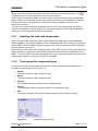
selected component type (see Figure 2–3):
•
Symbol
The basic symbol for the component type
•
Name
The name entered in the component type
•
Version
The version information entered in the component type
•
Library
The information about the library entered in the component type
•
UID
The unique identifier that is automatically assigned to the component type
Figure 2–3:
Copyright Siemens AG, 2013
Process Automation
Component type preview
SIMIT 7 – CTE
Page 6
User interface
s
3
USER INTERFACE
The component type editor (CTE) is a stand-alone SIMIT application. You start it from the
Start menu in the Programs | SIMIT 7 | CTE folder. Once it has started, you have the choice
of opening an existing component type, creating a new component type or migrating a
component type exported from SIMIT V5.4 SP1. You can also access this dialog (Figure 3–
1) at any time via the Components menu.
NOTE
In the CTE user interface, the shortened term 'component' is used, rather than
'component type' as the context in which it is used is clear enough to avoid
confusion.
Figure 3–1:
Copyright Siemens AG, 2013
Process Automation
Selection dialog for the CTE
SIMIT 7 – CTE
Page 7
User interface
s
NOTE
The migration of components from older versions of SIMIT is described in the
"Migration" manual.
You can also open component types for editing from the Components taskcard. Double click
the component type you want to open or select the Open command from its context menu
(Figure 3–2). If CTE was not yet running, CTE will open automatically.
Figure 3–2:
Context menu of a component type
Component types are stored on the file system in a file with a name ending with simcmp.
You may also open a component type in CTE by double clicking the file. Here, too, CTE is
lauchned to open the component type, if CTE was not running already.
3.1
Structure of the user interface
The CTE user interface (Figure 3–3) is based on the SIMIT GUI concept. It is subdivided into
the following palettes:
The menu bar and toolbar allow easy access to the CTE functions. There are additional
functions available in the pop-up menus.
The project window shows the open component type in a tree view.
The editors are opened for editing in the working area. Every editor contains a toolbar for
rapid access to the editor-specific functions.
The Tool window contains the tools that can be used with the editor concerned, such as
connector types and graphics tools in task cards.
The Property window shows the properties of an object selected in the working area.
The editor bar at the bottom left of the GUI allows you to toggle between opened editors.
The status bar at the bottom right of the GUI shows information about the current status of
the CTE.
Copyright Siemens AG, 2013
Process Automation
SIMIT 7 – CTE
Page 8
User interface
s
Figure 3–3:
The CTE user interface
All editors are opened in the working area. The tools window only contains the task cards
specific to the editor concerned. There are menu commands that divide the working area
horizontally (Window | Tile horizontally) or vertically (Window | Tile vertically) so that two
editors can be opened side by side or one below the other in the working area.
3.2
Menu bar and toolbar
The CTE menu bar contains all the commands you will need to create or open and edit
component types (Figure 3–4).
Copyright Siemens AG, 2013
Process Automation
SIMIT 7 – CTE
Page 9
User interface
s
Figure 3–4:
The menus in the CTE menu bar
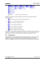
Frequently used functions are also provided on the toolbar. Specifically these are the
following functions:
•
(New Component) for creating a new component type
•
(Open ...) for opening a component type
•
(Save) for saving a component type
•
(Cut) for cutting selected objects
•
(Copy) for copying selected objects
•
(Paste) for pasting copied objects
•
(Update) for updating a component type
Some aspects of a component type affect one another. The Update function ensures that all
information in one aspect is compared with the information in the other aspects. When you
update, there is also a check to ensure that the component was written to correctly.
3.3
Project tree
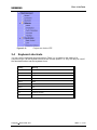
The project tree lists all the aspects of a component type (Figure 3–5). For every aspect an
associated editor can be opened by double clicking the relevant entry in the project
hierarchy. Formal errors in the implementation of an aspect are identified by an overlay in
the project tree: . All the higher levels of this aspect are identified with this overlay as well.
Copyright Siemens AG, 2013
Process Automation
SIMIT 7 – CTE
Page 10
User interface
s
Figure 3–5:
3.4
Project tree for the CTE
Keyboard shortcuts
You can use the keyboard shortcuts listed in Table 3–1 to speed up the editing of a
component type. All the keyboard shortcuts are context-specific, i.e. they can only be used if
the associated editor has the keyboard focus.
Hotkey
Meaning
Ctrl-A
Select all
Ctrl-C
Copy
Ctrl-F
Find
Ctrl-H
Replace
Ctrl-S
Save
Ctrl-V
Paste
Ctrl-X
Cut
F2
Rename
F3
Continue search
F5
Update
Table 3–1:
Keyboard shortcuts
Copyright Siemens AG, 2013
Process Automation
SIMIT 7 – CTE
Page 11
General Properties of a Component Type
s
4
GENERAL PROPERTIES OF A COMPONENT
TYPE
General properties of a component type concern
•
Administration
•
Protection
•
Specifics and
•
Changes
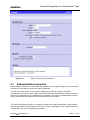
of that component type. To edit the general properties open the corresponding editor (Figure
4–1) by double clicking the aspect General in the project tree. The general properties editor
provides a fixed arrangement of input boxes to edit the individual properties.
Copyright Siemens AG, 2013
Process Automation
SIMIT 7 – CTE
Page 12
s
Figure 4–1:
4.1
General Properties of a Component Type
Editor for the general properties
Administration properties
Administration information is the name and version of the component type, plus the identifier
and family of the library to which this type is assigned.
You can enter any name. This is used to display the component type in the SIMIT
Components task card. It is thus also used as the basis for automatically assigning a name
when the component type is instantiated on a diagram. The name is independent of the file
name under which the component type is stored in the file system.
The version and library family of a component type can be defined arbitrarily, these values
are solely provided as information for the user. They are displayed in the Components task
card preview, but are not analyzed any further.
Copyright Siemens AG, 2013
Process Automation
SIMIT 7 – CTE
Page 13
s
General Properties of a Component Type
When chaning the name or version of a component type, saving the component will
automatically yield a file selection dialog so that you can also save the component under a
new filename. The default filename will match the component types name.
Libraries that are included in the SIMIT product range have a predefined library ID. The
library ID is entered in every component type in a library. When you create user
components, the library ID will be set to "0" automatically.
The File location of the component type in the file system and its unique identifier UID are
displayed for information.
4.2
Protection of the component type
You can assign a password to prevent the component type you have created being opened
in CTE by unauthorised persons. To do this, simply enter a password. You will be prompted
to enter the password again, just to check that you entered it correctly.
When you attempt to open a password-protected component type, the prompt as shown in
Figure 4–2 appears.
Figure 4–2:
Password prompt
The component type cannot be opened unless you enter the correct password. The
password protection has no effect on the use of a component type in SIMIT; it can be
dragged onto a diagram, instantiated and interconnected, just like any other component
type.
WARNING
STOP
4.3
Keep the password safely. Without the right password, you will not be able to
open this component type in the component type editor, even though you
created it!
Specifics
A component type may be assigned the special general property of "graphically scalable". In
this case, the component type has exactly one connector (Graphically scalable connection)
defined as an input or output which can be changed to any number in every instance. The
number of connectors is set on the diagram by scaling the symbol vertically using its grab
handle on the selection border (Figure 4–3).
Copyright Siemens AG, 2013
Process Automation
SIMIT 7 – CTE
Page 14
s
Figure 4–3:
General Properties of a Component Type
Setting the number of inputs on the component symbol
To set this property, use the Is graphically scalable option in the editor and specify which
connector can be scaled graphically (Figure 4–4).
Figure 4–4:
The "graphically scalable" property in the editor
The graphically scalable connection must be defined as a vector of connectors of which
there is a variable number (Figure 4–5), wherein the number must be created as a
parameter of the type dimension (Figure 4–6).
Figure 4–5:
Defining a vector of connectors of variable length
Figure 4–6:
Defining a dimension parameter
A component type may have other connectors in addition to the one that is graphically
scalable. The graphically scalable connection must always be positioned on its symbol
beneath all the other connectors, however.
Copyright Siemens AG, 2013
Process Automation
SIMIT 7 – CTE
Page 15
s
4.4
General Properties of a Component Type
Changes
The changes in the component type are for documentation purposes only and are not
evaluated by SIMIT. They can be used to keep the change history of a component type, for
example.
Copyright Siemens AG, 2013
Process Automation
SIMIT 7 – CTE
Page 16
s
5
Connectors of a Component Type
CONNECTORS OF A COMPONENT TYPE
The connectors of a component primarily define the interface that is used to exchange
information with other components. Connectors are also used to incorporate signals in their
operating window. All the connectors of a component type are edited in the connector editor,
which is set out like a table editor as seen in Figure 5–1. You can open the Connectors
editor by double clicking the aspect Connectors in the project tree.
Figure 5–1:
The table editor for connectors
Every connector is identified by the following properties:
•
Name
Every connector must have a unique name. The name must contain only letters,
digits and the underscore character, and must start with a letter. The name is case
sensitive. Reference is made to the name of a connector in the behaviour description,
for example.
Copyright Siemens AG, 2013
Process Automation
SIMIT 7 – CTE
Page 17
s
•
Connectors of a Component Type
Connection type
All connectors in SIMIT are typed, i.e. the connection type precisely defines which
information can be exchanged via a connector of this type. Connectors must always
be of the same type so that they can be connected to one another on a diagram. The
available connection types are suggested in a selection box.
•
Direction
The direction defines whether the connector is defined in the IN or OUT direction.
Binary, integer and analogue connectors are thus defined as inputs or outputs.
The special case of a connector without a direction (NONE) is only of relevance in
association with special libraries. You will find further details in the manuals for these
libraries.
•
Number
If you have entered a value other than the default number one, then you have a
connector vector with the specified number of elements. These connectors are simply
numbered consecutively in the component instance by appending an index number
starting with one to the name.
You can also enter a parameter that determines the number of connectors as the
number. This parameter must then be of the type dimension.
•
Default
Connectors that are defined as inputs can be given a default numerical value. This
default setting can be overwritten in every component instance.
Connectors also have other properties that can be defined in the property window for every
connector:
•
Usage
A connector can be used in different ways. The connector should generally be visible
on a diagram at the component symbol and thus allow it to be interconnected with
other components. Set the Usage to Symbol and property view to do this.
If you want the connector to only be visible in the property view for a component, and
not on the component symbol on the diagram, set the usage to In property view only.
This connector will then be permanently identified as an invisible connector by the
in the property window for the component.
symbol
The In CTE only setting allows the connector to be used in the component type, but
not to be visible on the symbol or in the component property window.
•
Visibility Default
If a connector has the usage Symbol and property view, you can set whether it is
) after instantiation on a diagram.
initially visible ( ) or invisible (
•
Implicit Connectable (for input signals only)
All connectors that have the usage Symbol and property view can also be implicitly
interconnected in the property window for the component instance. The Implicit
connectable property is permanently set for this usage.
Here you can define whether connectors with the usage In property view only should
be implicitly connectable connectors or not. If you set a connector with this usage to
not implicitly connectable, then only the default assignment for this connector can be
overwritten in the property window for the component. If you set it to Implicit
connectable, then the Value/Signal Default is changed to Signal.
Copyright Siemens AG, 2013
Process Automation
SIMIT 7 – CTE
Page 18
s
•
Connectors of a Component Type
Value/Signal Default (for input signals only)
If the usage of the connector is set to Symbol and property view, you can determine
whether the connector is set to Value ( ) or Signal ( ) by default in the component
instance.
If the default is Signal, the visibility default setting is automatically set to Not visible.
•
Is moveable
This allows you to define whether the connector in the component instance may be
moved on the outer edge of the component. Hold down the "Alt" button and drag the
connector with the mouse to move it.
•
Description
The description of a connector is for documentation purposes only and is not
evaluated by SIMIT.
•
Connection type ID
The name of a connection type does not have to be unique, so the unique ID allows
you to identify it if you are in any doubt.
5.1
Special default setting for implicitly connectable
inputs
Inputs are normally set by default to a numerical value for analogue and integer inputs or the
value True/False for binary inputs. If the default setting for Value/Signal is set to Signal ( ),
there is another option for the default setting: You can now set a default signal name (Figure
5–2).
Copyright Siemens AG, 2013
Process Automation
SIMIT 7 – CTE
Page 19
s
Figure 5–2:
Connectors of a Component Type
Setting an input to a signal by default
for this input is then set to the signal name specified in the property window
The symbol
for an instance of the component. This input of the component is thus permanently
interconnected to the output of another component. For the sample signal illustrated in
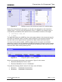
Figure 5–2, this is the output T of a component with the name GlobalValues (Figure 5–3).
Copyright Siemens AG, 2013
Process Automation
SIMIT 7 – CTE
Page 20
Connectors of a Component Type
s
Figure 5–3:
Setting an input in the component instance to a default signal
Rather than fixed names for the signal, you can also use parameters or the component
instance name. To do this, write the parameter name or _NAME for the instance name in
curly brackets, preceded by the $ symbol for the source and/or connector of the signal:
•
{$Parameter name} or
•
{$_NAME}.
The parameter name and _NAME are thus merely space holders in the component type for
the values of Parameter value or Instance name assigned in the component instance. You
can also make up the signal name as required from space holders and fixed names.
You may use the system variable _INDEX to define implicit connections for individual
elements of a vector. Use the expression {$_INDEX} as shown in Figure 5–4 in an example.
When instanciating the component this expression will be replaced in each element by this
elements index, index counting starting at one.
Figure 5–4:
Using the system variable _INDEX
When for a component according to the example in Figure 5–4 the values
•
Parameter MaxObjects is set to 2 and
•
Parameter BaseName is set to “LifterBase#1”
This yields the following default values for the input vector XPosition:
•
XPosition1:
LifterBase#1 XPositionOut1
•
XPosition2:
LifterBase#1 XPositionOut2
Copyright Siemens AG, 2013
Process Automation
SIMIT 7 – CTE
Page 21
Connectors of a Component Type
s
5.2
Complex connection types
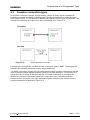
In the basic connection concept, a single analog, integer or binary signal is transferred
between connected connectors of components. The signal connection is always directed
from output to input, i.e. the direction is determined implicitly from the type of connector. This
concept for connecting an output to an input is sketched out in Figure 5–5.
Figure 5–5:
Basic connection concept
Connections of this type are provided as basic connection types in SIMIT. These types are
offered in the selection screen as analog, integer and binary.
The SIMIT connection concept is a little wider than this basic concept: a connection may be
used to transfer multiple signals between connectors in both directions. The direction of a
signal thus can no longer be derived from the connected connectors, so it needs to be
defined as a forward or backward signal in the connection type. Forward signals are
transferred from an output to an input; backward signals are exactly the reverse. Such a
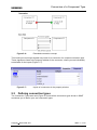
complex connection is depicted in Figure 5–6.
Copyright Siemens AG, 2013
Process Automation
SIMIT 7 – CTE
Page 22
Connectors of a Component Type
s
Figure 5–6:
Extended connection concept
Thus both input and output signals may result for a connector of a complex connection type.
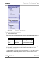
These signals are listed in the property window for the connector, where you can individually
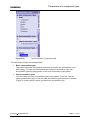
set defaults for the inputs (Figure 5–7).
Figure 5–7:
5.3
Inputs of a connector in the property window
Defining connection types
The Connection Types task card (Figure 5–8) lists all the connection types known in SIMIT
and allows you to define your own connection types.
Copyright Siemens AG, 2013
Process Automation
SIMIT 7 – CTE
Page 23
Connectors of a Component Type
s
Figure 5–8:
Connection Types task card
This task card is divided into three palettes:
•
Basic connection types
This section shows the connection types that are used in the component types in the
basic library. These are essentially the basic connection types as described in Table 5–1.
Connection type
Value
Range of values
binary
Binary values
True/False
analog
Floating point values
±5.0 × 10
integer
Integer values
-9,223,372,036,854,775,808 to
+9,223,372,036,854,775,807
Table 5–1:
-324
to ±1.7 × 10
308
Basic connection types
You can use the basic connection types as the basis for your own connection types. To
do this, copy the connection type to the User connection types palette and edit it.
•
User connection types
This palette allows you to create your own connection types. To do this, copy an existing
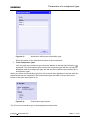
connection type or click the New connection type entry. A window (Figure 5–9) then
opens in which you define the signals.
Copyright Siemens AG, 2013
Process Automation
SIMIT 7 – CTE
Page 24
Connectors of a Component Type
s
Figure 5–9:
Defining a connection type
You can create any number of signals in the Forward and Backward direction. For the
signal type, you can only choose between the analog, binary and integer data types.
If you want to allow a component output to be connected to one or more inputs, then you
must check the Multiple Connection checkbox in the connection types. Multiple
connections are not permitted for connection types that contain backward signals,
otherwise multiple output signals would be routed to the same input. You can thus only
check the Multiple Connection check box if no signals are defined in the backward
direction.
When you close the dialog, a unique identification number (ID) is assigned to this
connection type.
•
From Component Types
When you create components and you want their connectors to be compatible with the
connectors of other components, it is important to use the same connection type for
them. To do this, you can open any component types from this palette on the task card
command. The connection types used in the component type will then not
using the
only be displayed under this component type, but will also be included in the selection list
of connection types.
When you select a connection type from one of these three palettes on the task card, the
signals that can be transferred using this connection type are listed in the preview at the
bottom of the task card (Figure 5–10):
Copyright Siemens AG, 2013
Process Automation
SIMIT 7 – CTE
Page 25
s
Figure 5–10:
Connectors of a Component Type
Connection type preview
The ID of the connection type is also displayed in the preview. Please note that connection
types are only identical if they have the same ID. The name of the connection type is not a
sufficient criterion. Connection types for which the same signals are defined are also not
identical.
Copyright Siemens AG, 2013
Process Automation
SIMIT 7 – CTE
Page 26
Parameters of a component type
s
6
PARAMETERS OF A COMPONENT TYPE
Instances of component types can be individually configured using parameters. To do this,
the relevant parameters must be provided in the component type. To define the parameter,
open the parameter editor (Figure 6–1) by double clicking the Parameter aspect in the
project tree.
Figure 6–1:
Editor for parameters
You can divide your parameters into two palettes: Primary and Secondary in order, for
example, to be able to isolate as primary parameters essential parameters that are generally
used to parameterize the components from inessential and thus rarely used secondary
parameters. If you define secondary parameters here, SIMIT will take this distinction into
account in the property window for the component instance. A further category (Additional
parameters, which contains the secondary parameters) will then appear in the property
window in addition to the Parameter category.
Parameters are identified by the following properties:
•
Name
Every parameter must have a unique name. The name must contain only letters,
digits and the underscore character, and must start with a letter. The name is case
sensitive.
•
Data type
Parameters can have one of the data types illustrated in Table 6–1.
Copyright Siemens AG, 2013
Process Automation
SIMIT 7 – CTE
Page 27
Parameters of a component type
s
Data type
Meaning
Range of values
binary
Binary values
True/False
analog
Floating point values
±5.0 × 10
integer
Integer values
-9,223,372,036,854,775,808 to
+9,223,372,036,854,775,807
dimension
Number of a connector or
parameter vector
1 .. 256
text
Single line of text
characteristic
Characteristic
Table 6–1:
-324
to ±1.7 × 10
308
Data types for parameters
All the enumeration types are also available for parameters. The enumeration types
are described in detail in section 6.1.
•
Dimension
If you have entered a value other than the default number one, then you have a
parameter vector with the specified number of elements. These parameters are
simply numbered consecutively in the component instance by appending an index
number starting with one to the name.
You can also enter as the number another parameter that determines the number of
this parameter. This parameter must then be of the type dimension.
•
Default
Parameters can be assigned a default numerical value.
Parameters also have other properties that you can edit in the property window for that
parameter.
•
Online-changeable
Online changeable parameters are parameters that can be changed for a component
instance while a simulation is running.
Parameters of the type dimension are not online-changeable.
•
Unit
The unit entered here only appears as an additional property of the parameter in the
property window for the component instance.
•
Comment
The comment for a parameter is for documentation purposes only and is not
evaluated by SIMIT.
All the names of parameters and connectors must be unique, i.e. a connector must not have
the same name as a parameter and vice versa.
6.1
Defining enumeration types
The Enumeration types (Figure 6–2) task card contains all the enumeration types that can
be used for enumeration parameters.
Copyright Siemens AG, 2013
Process Automation
SIMIT 7 – CTE
Page 28
Parameters of a component type
s
Figure 6–2:
The Enumeration Types task card
This task card is divided into three palettes:
•
Basic enumeration types
This palette shows the enumeration types that are used in the components in the
basic library. You can use these enumeration types as the basis for your own
enumeration types by copying them to the User enumeration types palette.
•
User enumeration types
You can create your own enumeration types in this palette. To do this, copy an
existing enumeration type or click the New enumeration type command. A window
(Figure 6–3) then opens in which you define the enumeration type.
Copyright Siemens AG, 2013
Process Automation
SIMIT 7 – CTE
Page 29
Parameters of a component type
s
Figure 6–3:
Window for defining an enumeration type
Enter the names for the individual elements of the enumeration.
•
From Component Types
You can open any component types from this palette on the task card using the
command. The enumeration types used in the component type will then not only be
displayed under this component type, but will also be included in the selection list of
enumeration types.
When you select an enumeration type from one of these three palettes on the task card, the
elements that can be contained in this enumeration type are listed in the preview at the
bottom of the task card (Figure 6–4).
Figure 6–4:
Enumeration type preview
The ID of the enumeration type is also displayed in the preview.
Copyright Siemens AG, 2013
Process Automation
SIMIT 7 – CTE
Page 30
s
Parameters of a component type
In the behaviour description you use an element of an enumeration type by entering the
name of the enumeration type, followed by a dot and the name of the actual element. The
entire construct must also appear in single quotes, for example: ’ClosedOpen.Closed’.
Copyright Siemens AG, 2013
Process Automation
SIMIT 7 – CTE
Page 31
The behaviour of a component type
s
7
THE BEHAVIOUR OF A COMPONENT TYPE
The functional behaviour of a component type is defined by state variables and the
behaviour description. The behaviour description is divided into the individual aspects of
Initialisation, Cyclic calculation and Functions. The component type editor provides suitable
editors for all aspects: a table editor for the states and a text editor for the sub-aspects of the
behaviour description.
7.1
States
State variables of a component are the memory of a component, as it were. They contain
values that, at any point in time, cannot be calculated from the input variables and
parameters alone, but depend on what has happened in the past. For example, the fill level
in a container cannot be calculated by simply balancing the inflow and outflow at a given
point in time; it also depends on the content of the container before the point under
consideration.
A table editor is provided for editing the states (Figure 7–1). You can open the editor by
double clicking the aspect States in the project tree.
Figure 7–1:
Table editor for the state variables
A state has the following properties:
•
Name
Every state variable must have a unique name. The name must contain only letters,
digits and the underscore character, and must start with a letter. The name is case
sensitive.
Copyright Siemens AG, 2013
Process Automation
SIMIT 7 – CTE
Page 32
The behaviour of a component type
s
•
State type
There are two different state types: time-discrete and continuous. The difference is
determined by how the new value of a state is calculated:
For time-discrete states, the value is calculated in every processing cycle by a
calculation rule in the form of an explicit equation that you define in the behaviour
description. The rule for calculating a continuous state variable is defined by a
differential equation. SIMIT calculates the state values in every processing cycle by
solving this differential equation using a suitable numerical method.
You will find detailed information about how to handle time-discrete and continuous
state variables using explicit equations and differential equations in the behaviour
description in the relevant section in chapter 9.2.
•
Data type
Time-discrete state variables can have any of the data types listed in Table 7–1.
Data type
Description
Range of values
binary
Binary values
True/False
analog
Floating point values
±5.0 × 10
integer
Integer values
-9,223,372,036,854,775,808 to
+9,223,372,036,854,775,807
byte
Byte
0 to 255
Table 7–1:
-324
to ±1.7 × 10
308
Data types for time-discrete states
Continuous state variables are always of the type analog.
•
Dimension
If you have entered a value other than the default number one, then you have a state
vector with the specified number of elements. These states are simply numbered
consecutively in the component instance by appending an index number starting with
one to the name.
You can also enter as the number another parameter that determines the number of
this parameter. This parameter must then be of the type dimension.
State variables also have other properties that can be defined in the property window for the
component type:
•
Default
Every state variable has a default setting suitable for its type. This default setting can
be overwritten in the component instance.
•
Only visible in CTE
Set this option if you do not want this state to be visible in the component property
window.
•
Description
The description of a state variable is for documentation purposes only and is not
evaluated by SIMIT.
Copyright Siemens AG, 2013
Process Automation
SIMIT 7 – CTE
Page 33
The behaviour of a component type
s
7.2
Initialisation, cyclic calculation and functions
The behaviour description for a component consists of a part that is executed once during
initialisation and a part that is carried out in every cyclic calculation step. Calculations that
are used multiple times can optionally be defined as functions. The component type editor
provides a text editor for each of these three sub-aspects of the behaviour description
(Figure 7–2). The editor for any of these sub-aspects can be opened by double clicking the
corresponding sub-aspect in the project tree.
Figure 7–2:
Text editor for the behaviour description
For ease of orientation, you can activate the Highlight syntax option in the property window.
Important elements of the description syntax are then made easier to identify by different
colours. Table 7–2 lists the colours used for the individual elements.
Element
Colour
Input signal
Green
Output signal
Red
State
Olive green
Parameter
Pink
Text constant
Brown
Keyword
Blue
Description
Grey
Table 7–2:
Copyright Siemens AG, 2013
Process Automation
Colours used for the elements
SIMIT 7 – CTE
Page 34
The behaviour of a component type
s
NOTE
The use of highlight colours increases the computing power needed to update
the user interface of the text editor, and the extra time needed is sometimes
sufficient to cause a short delay while you are typing. You may therefore find it
useful to switch off the highlighting, at least temporarily, if your texts are very
long.
All three text editors have a function for finding and replacing text located beneath the
icon. You can also call up this function using the Ctrl+F or Ctrl+H shortcuts. There are
various options you can use for searching, as shown in Figure 7–3.
Figure 7–3:
Find and Replace in the text editor
The syntax for the behaviour description is described in section 0.
7.3
The Signals task card
For every behaviour description text editor there is a Signals task card. This contains all the
signals that exist in this component type. Here the "source" of signals is the actual
component type, so you only need the name for the signals in this case.
Copyright Siemens AG, 2013
Process Automation
SIMIT 7 – CTE
Page 35
s
Figure 7–4:
The behaviour of a component type
The Signals task card
The task card signals allow you to filter by name, signal type and data type. It thus provides
a rapid overview of the signals available in this component type. You can also easily drag a
signal name from the signal task card into the text editor, thus ensuring that you do not make
any typing errors, for example.
7.4
Topology
The topology description is only meaningful in association with special libraries. You will find
further details concerning topology aspects in the manuals for these libraries.
Copyright Siemens AG, 2013
Process Automation
SIMIT 7 – CTE
Page 36
s
8
Visualization of component types
VISUALIZATION OF COMPONENT TYPES
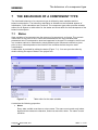
A graphical representation of a component instance is created in the form of a basic symbol
for every component type. The basic symbol is displayed in the preview of the task card
component; it represents every component instance on the diagram.
Optionally a link view can be created for a component type. This provides additional access
to the component instance. It is also possible to define an operating window for a component
type that can be opened for every instance while the simulation is running in order to set and
display component values.
8.1
The basic symbol
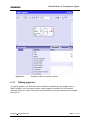
To edit the basic symbol, open the graphical symbol editor (Figure 8–1) by double clicking
the Basic symbol aspect in the project tree. The Graphics task card contains the graphical
elements of the diagram editor for designing the graphical aspects of the basic symbol. You
can use these graphical functions to design the basic symbol as required in the available
space.
Copyright Siemens AG, 2013
Process Automation
SIMIT 7 – CTE
Page 37
Visualization of component types
s
Figure 8–1:
8.1.1
Graphical editor for the basic symbol
Editing graphics
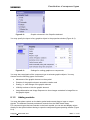
For editing graphics you have the full set of features available that the graphic editor in
SIMIT provides. You may drag and drop various graphic elements from the Graphics
taskcard (Figure 8–2) onto the symbol view and edit them using the features as provided in
the tool bar.
Copyright Siemens AG, 2013
Process Automation
SIMIT 7 – CTE
Page 38
Visualization of component types
s
Figure 8–2:
Graphic elements in the Graphics taskcard
You may specify the layout of any graphics object in the properties window (Figure 8–3).
Figure 8–3:
Settings for scaling graphics on components
You may also use signals of the component type to animate graphic objects. You may
choose from the following types of animation
•
Movement of the graphic element on the symbol
•
Rotation of the graphic element around the rotation axis
•
Scaling, i.e. size change of the graphic element
•
Visibility to show or hide the graphic element
•
Image Alternation and Image Sequence to show images contained in image files on
the graphic object
8.1.2
Adding controls
You may also place controls on the basic symbol and connect them to input or output
signals. The taskcard Controls provides all controls from the SIMIT basic library.
For component types that use controls on the basic symbol you can set and display values
directly on the symbol without having to open the component types operating window (Figure
8–4).
Copyright Siemens AG, 2013
Process Automation
SIMIT 7 – CTE
Page 39
Visualization of component types
s
Figure 8–4:
8.1.3
Component type with a pushbutton on the basic symbol
Editing connectors
All connectors as specified in the connectors editor can be automatically arranged on the
in the toolbar. Connectors are automatically
basic symbol. Just click the symbol
arranged in a specified order on the border of the basic symbol: Inputs are placed on the left
hand side, outputs on the right hand side. You may use the mouse to drag any connector to
the desired position within a raster of 5 pixels.
A connectors coordinates are displayed in the properties view (Figure 8–5), you can also
manually edit the desired position there. In contrast to positioning with the mouse, manual
input is not limited to the raster. Coordinates also do not need to be integer values.
Figure 8–5:
Position of a connector
If there is a vector of inputs or outputs that has a fixed, i.e. not variable dimension, each
individual connector of that vector can be freely positioned.
8.1.4
NOTE
Changes in the connector editor do not appear in the symbol editor until you
save the component type or run an update from the toolbar ( ) or by pressing
function key F5.
Editing properties
You can define properties for the basic symbol in the property window:
•
Name
If you enter a Name, this appears centred at the top of the basic symbol and is offset
from the rest of the area by a horizontal separating line (Figure 8–6).
Copyright Siemens AG, 2013
Process Automation
SIMIT 7 – CTE
Page 40
Visualization of component types
s
Figure 8–6:
Name of the basic symbol
When combined with the Draw border option, this represents a rudimentary way to
design a component view.
•
Width
Here you can specify the Width of the basic symbol in pixels as a numerical value.
Alternatively, you can hold down the left mouse button on the left or right edge of the
symbol area in the editor window to move it. The numerical value for the width will
change automatically as you do so.
•
Height
Here you can specify the Height of the basic symbol in pixels as a numerical value.
Alternatively, you can hold down the left mouse button on the top or bottom edge of
the symbol area in the editor window to move it. The numerical value for the height
will change automatically as you do so.
•
Horizontal scalable
The Horizontal scalable option is used to define whether the basic symbol for the
component instance should be scalable in the horizontal direction on a diagram.
Suitable grab handles are then provided on the selection border for the basic symbol
(Figure 8–7).
Figure 8–7:
•
Horizontally non-scalable (a) and scalable (b) symbols
Vertical scalable
The Vertical scalable option is used to define whether the basic symbol for the
component instance should be scalable in the vertical direction on a diagram.
Suitable grab handles are then provided on the selection border for the basic symbol
(Figure 8–8).
Copyright Siemens AG, 2013
Process Automation
SIMIT 7 – CTE
Page 41
s
Figure 8–8:
•
Visualization of component types
Vertically non-scalable (a) and scalable (b) symbols
Minimal width
The Minimal width of the basic symbol cannot be undershot when scaling the basic
symbol horizontally on the diagram.
•
Minimal height
The Minimal height of the basic symbol cannot be undershot when scaling the basic
symbol vertically on the diagram.
•
Scale graphics
If you design a scalable basic symbol with graphics, this option allows you to define
whether the graphic should be scaled with the basic symbol (Figure 8–9).
Figure 8–9:
•
Graphic of the basic symbol (a) is not scaled with the basic
symbol (b) or is scaled with the basic symbol (c)
Is rotatable
This option defines whether the basic symbol can be rotated on a diagram or not. If it
is rotatable, a suitable grab handle appears on the selection border of the basic
symbol (Figure 8–10).
Copyright Siemens AG, 2013
Process Automation
SIMIT 7 – CTE
Page 42
Visualization of component types
s
Figure 8–10:
•
Component is not rotatable (a) and is rotatable (b)
Show connector names
This option allows you to define whether the connector names of the inputs and
outputs should be displayed in the symbol. Please note that inputs can only be
displayed on the left-hand edge and outputs on the right-hand edge of the basic
symbol.
Figure 8–11:
•
Representation of the connector names on the basic symbol
Draw border
This option allows you to define whether the basic symbol should appear with a black
border.
Figure 8–12:
•
Border of the basic symbol
Proportional scalable only
This option can be used to specify that a components with and height cannot be
scaled independently but only proportionally, i.e. maintaining a constant ratio
between width and height. This option can only be selected when the component is
both horizontally and vertically scalable!
•
Scale
Copyright Siemens AG, 2013
Process Automation
SIMIT 7 – CTE
Page 43
s
Visualization of component types
When creating user component types for material transport (i.e. component types
with library type CONTEC) you may specify a scale for the basic symbol. This scale
fulfils two tasks:
1. All sizes and positions can be defined in millimetres according to the scale
specified when creating the symbol of a material transport component.
2. When creating the symbol of a material transport component the size as
resulting from the specified scale is the default size with which the material is
placed into the material list in SIMIT.
8.2
NOTE
The property Scale is available only if you have the CONTEC library licensed in
SIMIT!
The link symbol
The basic symbol of a component type is used to parameterize and link the component
instance on a diagram. Optionally, a component type can have a link view. The symbol
shown in this view (the link symbol) may be designed graphically entirely independently of
the basic symbol. It has no connectors, in contrast to the basic symbol. Otherwise, the
graphic elements of the link symbol can be freely designed as in the basic symbol, i.e. they
can be animated, for example, to visualize current simulation states of a component
instance.
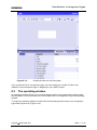
Double click the Link entry in the project tree to open the editor for the link symbol (Figure 8–
13). The graphical editor that opens provides the same functions as the basic symbol editor,
apart from the functions that relate to connectors.
Copyright Siemens AG, 2013
Process Automation
SIMIT 7 – CTE
Page 44
Visualization of component types
s
Figure 8–13:
Graphical editor for the link symbol
If you provide a link for a component type, you can create any number of links for an
instance of this component type on diagrams in your SIMIT project.
8.3
The operating window
An operating window allows you to set and display values of the component instance while
the simulation is running. Double click the components in the diagram to open the operating
window.
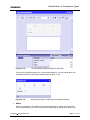
To create an operating window, double click the Operating window entry in the component
type editor project tree (Figure 8–14).
Copyright Siemens AG, 2013
Process Automation
SIMIT 7 – CTE
Page 45
s
Figure 8–14:
Visualization of component types
Editor for the operating window
You can use all the controls for the SIMIT basic library in an operating window. These
controls are provided on the Controls task card. You can drag these controls from the task
card onto the drawing surface of the editor and connect them to suitable input or output
signals for the component type.
The Graphic task card also provides the SIMIT graphic functions for graphically designing
the operating window. Please note that graphic objects in the operating window cannot be
animated.
The property window contains further options for designing the operating window:
•
Extended window
You can divide the operating window into two areas in order to separate frequently
required controls from those that are needed less often, for example. To do this,
activate the Extended window option. The editor then contains another area for the
extended window (Figure 8–15). This area is just as wide as the area for the
operating window, and the height can be changed as required.
Copyright Siemens AG, 2013
Process Automation
SIMIT 7 – CTE
Page 46
s
Figure 8–15:
Visualization of component types
The extended operating window in the editor
In the open operating window for a component instance, you can easily open the
extended window by clicking the bottom edge (Figure 8–16).
Figure 8–16:
•
Operating window for opening the extended window
Width
Here you can specify the width of the operating window in pixels as a numerical
value. Alternatively, you can move the left or right edge of the window area in the
Copyright Siemens AG, 2013
Process Automation
SIMIT 7 – CTE
Page 47
s
Visualization of component types
editor by holding down the left mouse button. The numerical value is updated
automatically.
•
Height
Here you can specify the height of the operating window in pixels as a numerical
value. Alternatively, you can move the top or bottom edge of the window area in the
editor by holding down the left mouse button. The numerical value is updated
automatically.
Copyright Siemens AG, 2013
Process Automation
SIMIT 7 – CTE
Page 48
s
9
Behaviour description
BEHAVIOUR DESCRIPTION
The behaviour description for a component consists of a part that is executed once during
initialisation and a part that is carried out in every cyclic calculation step. The same
description syntax applies to both parts.
There are two different approaches to the behaviour description for a component:
•
Equation-oriented approach
The equation-oriented approach describes every new status value or output value as
an explicit function of the inputs, parameters and states. It is particularly suitable for
modelling physical contexts. This approach allows you to describe the change in
continuous state variables using common differential equations as well.
•
Instruction-oriented approach
The instruction-oriented approach describes the calculation of new state variables or
outputs in the form of programming instructions that are processed sequentially in the
specified order. This approach is particularly suitable for modelling technical
behaviour.
The two approaches can also be combined in a component type.
9.1
Conversion of the behaviour description to C# code
Regardless of which approach is used to define the behaviour of a component type, it is
ultimately converted into C# code in the simulation project for every component instance.
This conversion takes place automatically and cannot be seen by and is of no significance to
the user.
Not all syntax errors are detected before the code is generated, so the compiler may also
generate error messages. Please note that the information in such error messages relates to
the generated code that differs from the behaviour specified in the component type in terms
of both syntax and breakdown.
9.2
The equation-oriented approach
In the equation-oriented approach, the syntax in which you set out the behaviour of your
component type consists of relationships in the form of equations, rather than instructions.
These equations explicitly describe how a state variable or an output is calculated from other
variables, for example as follows:
Output = Parameter * Input;
Essentially:
•
Every equation contains the equals sign.
•
On the left of the equals sign is the variable that is being determined. On the right of
the equals sign are the variables that are read (explicit form of an equation).
•
At the end of every equation there is a semicolon.
•
Any variable may occur only once on the left of the equals sign, i.e. a variable may
only be determined once.
The following variables may appear on the left of the equals sign:
•
Outputs
Copyright Siemens AG, 2013
Process Automation
SIMIT 7 – CTE
Page 49
Behaviour description
s
•
States (for time-discrete states, only the new value; for continuous states, only the
differential, i.e. the change in value) and
•
Local variables.
The following variables may appear on the right of the equals sign:
•
Inputs
•
States (only the differential may appear here for continuous states)
•
Parameters
•
Local variables and
•
Constants
9.2.1
Local variables
You can define local variables as follows in the behaviour description for initialisation or
cyclic calculation:
Data type Name[,Name];
Example:
binary b1, b2, b3;
The data types listed in Table 9–1 are permitted.
Data type
Description
Range of values
binary
Binary values
True/False
-324
Default
False
308
analog
Floating point values
±5.0 × 10
integer
Integer values
-9,223,372,036,854,775,808 to
+9,223,372,036,854,775,807
Table 9–1:
to ±1.7 × 10
0.0
0
Data types for local variables
The name of a local variable must contain only letters, digits and the underscore character,
and must start with a letter.
Local variables are used to save interim results that will be needed again in the same
processing step. In the subsequent calculation step, local variables have their originally
assigned value once more.
If you wish to access calculated values once more in the next calculation step, always create
time-discrete state variables, rather than local variables.
9.2.2
Constants
The constants you can use will depend on the data type of the result variable. The constants
for each data type are described in Table 9–2.
Copyright Siemens AG, 2013
Process Automation
SIMIT 7 – CTE
Page 50
Behaviour description
s
Data type
Constants
binary
"FALSE" or "TRUE"
analog
Decimal fraction with a decimal points as the separator, e.g. "125.61"
Exponential notation, e.g. 62.2e-4"
integer
Sequence of digits without a thousands separator, e.g. "125985"
Table 9–2:
9.2.3
Data types for constants
The calculation order
The behaviour description for a component type both for initialisation and for cyclical
calculation consists of individual equations. With the description you are only describing
relationships and dependencies in those relationships. In particular, you are not defining any
order for the calculation. The order in which you write these equations is of no relevance to
the calculation.
When you generate an executable simulation, SIMIT analyzes all the equations in a
component instance and determines the order in which they need to be calculated with
reference to the interdependencies. SIMIT always arranges the calculation order so that
equations that define a variable are calculated before equations in which this variable is
needed.
In the example in Figure 9–1, the local variable p is first assigned the value 3.14, then the
new state Z is calculated and then the value of the newly calculated state is assigned to the
output.
Figure 9–1:
Example of an equation-oriented behaviour description
The calculation order is automatically obtained from the analysis of the dependencies and, in
this case, is exactly the reverse of the order in the description.
However, SIMIT does not analyze the equations within a single component instance, but
rather across all the component instances with their reciprocal links in your SIMIT project
and defines a suitable calculation order for the project. In the example in Figure 9–2,
multiplication is always carried out before addition because the product is needed for the
addition.
Copyright Siemens AG, 2013
Process Automation
SIMIT 7 – CTE
Page 51
s
Figure 9–2:
Behaviour description
Example of a defined calculation order
Situations may occur in which no unique calculation order can be determined. In the
example in Figure 9–3, the input values of the two AND operations are independent of the
output value of the other operation. This feedback means that one of the two AND
operations is always calculated with a non-current input value, i.e. with a value originating
from the previous calculation cycle.
Figure 9–3:
Example of an undefined calculation order
In such cases the order in which the equations must be processed is not defined, but SIMIT
always attempts to maximize the calculation order, i.e. to sort as many equations as possible
into an order. Thus, in the above example, SIMIT always processes the "Switch - AND - NOT
- binary indicator" sequence in this order. It is also not defined whether the top or the bottom
sequence should be processed first.
9.2.4
Operators
The variables on the right of the equals sign can be linked to one another with operators.
The operators listed in Table 9–3 are permitted, depending on the data type.
Copyright Siemens AG, 2013
Process Automation
SIMIT 7 – CTE
Page 52
Behaviour description
s
Operation
Operator
Data type
Priority
Brackets
(expression)
binary, integer, analog
highest
Function call
Function name (parameter list)
binary, integer, analog
Conversion
-
integer, analog
Negation
NOT
binary
Multiplication
*
integer, analog
Division
/
integer, analog
Modulo
%
integer
Addition
+
integer, analog
Subtraction
-
integer, analog
Comparison
<, >, <=, >=
integer, analog
Equality
=
binary, integer, analog
Inequality
!=
binary, integer, analog
Logical AND
AND
binary
Logical exclusive
OR
XOR
binary
Logical OR
OR
binary
Table 9–3:
9.2.5
lowest
Permitted operators
Conditional expressions
You can assign different values with the following syntax to a variable, according to one or
more conditions:
y = {Condition1: Expression1; Condition2: Expression2; ...
Example:
ELSE Expression0};
m = {p<1: m1; p<0: m2; ELSE m3};
The conditions are processed from left to right. Once a condition is fulfilled, the associated
expression is evaluated and assigned to the variable on the left of the equals sign. If no
condition is fulfilled, the expression after the keyword ELSE is evaluated.
You can specify as many condition/expression pairs as you wish. The "ELSE" expression
must always be specified.
9.2.6
Enumeration types
Parameters can have enumeration types as the type. You can then select the desired entry
from a list in the property window of the diagram editor in order to parameterize the
component instance (Figure 9–4).
Copyright Siemens AG, 2013
Process Automation
SIMIT 7 – CTE
Page 53
Behaviour description
s
Figure 9–4:
Parameterising with an enumeration
You can look up such parameters in the behaviour description by relating the corresponding
list entry to the name of the enumeration type, separated by a dot, as shown in the following
example:
9.2.7
Vectors
You can also define all inputs, outputs, parameters and states as vectors. You can then
access the elements of the vector in the behaviour description as follows:
• Individual elements
To access an element of a vector, append the desired index in square brackets to the
signal name.
Please note that the first element of the vector has index 0. The index must be a
constant, non-negative integer value and must not exceed the number of elements that
this vector has.
Example:
Output[2] = Input * 2.0;
• Range
You can specify an equation for multiple elements of a vector by entering a range:
Vector_name[Index1 TO Index2]
SIMIT resolves this vector equation so that the following two examples are identical:
Example 1:
Output[0 TO 2] = 1.0;
Example 2:
Output[0] = 1.0;
Output[1] = 1.0;
Output[2] = 1.0;
When you want to refer to the index in a vector equation, you can specify an index
variable:
Vector_name[Index variable: Index1 TO Index2]
This index variable can then be used on the right-hand side of the equation. It does not
also have to be declared as a local variable. Its name must be a single character!
Example:
Copyright Siemens AG, 2013
Process Automation
SIMIT 7 – CTE
Page 54
Behaviour description
s
Output[i:0 TO 2] = Input[i + 1];
In this case, the resolution into individual equations is as follows:
Output[0] = Input[1];
Output[1] = Input[2];
Output[2] = Input[3];
• Whole vector
If you want to extend the range to the whole vector, you can also write:
Vector_name[ALL]
or by specifying an index variable:
Vector_name[Index variable: ALL]
• Vector of a complex variable
If a signal has a complex connection type, the index is specified in square brackets at
the end of the complete name.
Example:
X1.Re[3] = Y1.Im[1] * Y2.Im[2];
9.2.8
Function calls for mathematical standard functions
You can use all the mathematical standard functions anywhere in your behaviour description
that a scalar input variable would be permitted.
Simply prefix the name of the mathematical standard function with an underscore and
append a list of parameters in round brackets. The individual parameters are separated by
commas. If a function has no parameters, it is called with an empty parameter list. Table 9–4
lists all the available mathematical standard functions.
Function
Return value
Description
_sqrt(x)
analog
y= x;
_abs(x)
analog/integer
y= x
_exp(x)
analog
y = ex
_pow(x, z)
analog
y = xz ;
_log(x)
analog
Natural logarithm: y = ln ( x ) ; x > 0
_log10(x)
analog
Common logarithm: y = lg( x ) ; x > 0
_ceil(x)
analog
Smallest integer greater than or equal to x
_floor(x)
analog
Largest integer less than or equal to x
_rand()
integer
Random value between 0 and 32767
_sin(x)
analog
y = sin (x ) ; Angle x in the radian measure
_cos(x)
analog
y = cos(x ) ; Angle x in the radian measure
_tan(x)
analog
y = tan (x ) ; Angle x in the radian
x≥0
measure x ≠ ±( 2n + 1 ) π 2
Copyright Siemens AG, 2013
Process Automation
SIMIT 7 – CTE
Page 55
Behaviour description
s
Function
Return value
_asin(x)
analog
y = arcsin (x ) ; − 1 ≤ x ≤ 1
_acos(x)
analog
y = arccos(x ) ; − 1 ≤ x ≤ 1
_atan(x)
analog
y = arctan(x ) ;
_atan2(y, x)
analog
y
x>0
arctan( x )
y
π + arctan( )
y ≥ 0, x < 0
x
− π + arctan( y ) y < 0, x < 0
y=
x
π
y > 0, x = 0
2
π
−
y < 0, x = 0
2
undefined
y = 0, x = 0
_sinh(x)
analog
y = sinh (x ) ; Angle x in the radian measure
_cosh(x)
analog
y = cosh (x ) ; Angle x in the radian measure
_tanh(x)
analog
y = tanh (x ) ; Angle x in the radian measure
_min(x, y)
analog/integer
The smaller of the two values x or y
_max(x, y)
analog/integer
The larger of the two values x or y
_trunc2byte(x)
byte
The integer part of x modulo 2
8
_trunc2int(x)
int
The integer part of x modulo 2
16
_trunc2long(x)
long
The integer part of x modulo 2
32
_round2byte(x)
byte
The rounded number x modulo 2
8
_round2int(x)
int
The rounded number x modulo 2
16
_round2long(x)
long
The rounded number x modulo 2
32
_characteristic(c[ALL], x)
analog
Special case of a characteristic (see section
9.5)
Table 9–4:
9.2.9
Description
List of mathematical standard functions
Self-defined functions
If you need your own operator you can define a self-defined function under the Functions
sub-aspect in the behaviour description. You can call self-defined functions in the
Initialization and Cyclic calculation sub-aspects.
When you call a self-defined function, you can also set multiple variables if you have
declared the function accordingly. When you call a self-defined function, always specify the
list of calculated function values in round brackets.
Example:
Copyright Siemens AG, 2013
Process Automation
SIMIT 7 – CTE
Page 56
s
Behaviour description
(y1, y2) = UserFunction(x1, x2);
Even a single function value as a return value must be placed in round brackets.
You can only use self-defined functions with a call as shown above. Even if your self-defined
function has only one return value, you cannot use this function like the mathematical
standard functions as a scalar value in other relationships; the function must always be
called as shown above.
The syntax used to describe functions differs significantly from the equation language. It
follows the instruction-oriented approach and is described in section 9.3.1.
9.2.10 Differential equations
If you have defined an analogue state of your component type as continuous, the behaviour
description does not specify how this state is calculated. Rather it states from which
variables and how this state changes over time: The change of state is defined in the form of
a standard differential equation.
9.2.10.1 Notation for the differential
The mathematical notation for the differential d/dt is abbreviated to a Dollar sign in SIMIT.
For example, for the change in the continuous state "Mass" in a container, you would write
an equation as follows:
$Mass = Inflow - Outflow;
The new value of the state variable is now determined by SIMIT in every step of the
computation by numerically solving the differential equation.
You can also describe multiple continuous states in your component type by differential
equations that are dependent on one another. This will then give the following system of
differential equations, for example:
$Z1 = Z2 + Factor1 * Z3 – Input1;
$Z2 = Factor2 * Z1;
$Z3 = Z1 + Z2;
To solve such standard differential equation systems, SIMIT uses a numerical solution
method based on the Runge-Kutta-Merson method.
As already discussed for defining the calculation order, the SIMIT global view again
accesses the simulation project: SIMIT not only handles the differential equations of a
component, but all the differential equations of the entire simulation project in a closed
manner, i.e. the differential equation system of the entire simulation model is mapped onto
the numerical solution method.
9.2.10.2 Corrections for the state variables
The simulation cannot generally take account of every aspect of reality. A simulation model
is thus simplified compared to reality and also applies only within a range defined by the
assumed requirements. The defined range for state variables can generally be exceeded
when solving differential equations. Typical situations are, for example, the states Container
empty and Container full when calculating the container fill level as described above. In
these cases, the state variables must be checked after solving the differential equation
system and corrected if necessary.
Copyright Siemens AG, 2013
Process Automation
SIMIT 7 – CTE
Page 57
Behaviour description
s
SIMIT allows you to write a conditional equation for correcting state variables. You simply
identify the correction value for the state by prefixing it with a # sign, and write a correction
equation as in the following example:
#Mass = {@Mass < 0.0: 0.0; ELSE @Mass};
In this equation, the value for Mass is set to 0.0 if the solution method has calculated a value
that is less than 0.0, otherwise the value for Mass is identical to the calculated value @Mass.
9.2.10.3 Accessing continuous state variables
As mentioned above, continuous state variables are also calculated cyclically. The values
are thus only available at the times defined by the cycle. In a given time step you can only
access the value in the previous calculation cycle and the newly-calculated or corrected
value. As can be seen in the list in Table 9–5, you access the newly-calculated value for a
state Z by prefixing it with an @ sign.
Notation
Access
Z
Value from the previous computation cycle
@Z
New value after integration of the status equation
#Z
Corrected value that is to be used in the next computation cycle in
place of @Z
Table 9–5:
Accessing continuous state variables
9.2.11 Accessing discrete state variables
For discrete state variables you define the initial value or the new value in each cycle with
the aid of an explicit equation. The new value for a state Z is identified by prefexing it with a
@ sign (see Table 9-6).
Notation
Access
Z
Value from the previous computation cycle
@Z
New value
Table 9-6:
9.3
Accessing discrete state variables
The instruction-oriented approach
The instruction-oriented approach is used to formulate user functions or entire function
blocks. No equations are used within self-defined functions and blocks; these are replaced
by program commands that are executed in the defined order. The syntax is identical within
the function or block definition.
9.3.1
Functions
Functions are created in the Functions sub-aspect of the behaviour description. Double click
the Functions entry in the navigation bar to open the text editor provided.
Copyright Siemens AG, 2013
Process Automation
SIMIT 7 – CTE
Page 58
Behaviour description
s
A function consists of the following elements:
•
The keyword FUNCTION,
•
The function declaration
•
The instruction part and
•
The keyword END_FUNCTION.
Syntax:
FUNCTION Function_name (Data_type Output variable1 [,
Data_type Output_variable2]) : (Data_type
Input_variable1 [, Data_type Input_variable2])
Instruction_part
END_FUNCTION
Only the basic data types binary, integer and analog are permitted as data types for the input
and output variables.
Example:
FUNCTION Trigonometry (analog y1, analog y2) :
(analog x1, analog x2, binary state)
if (state) {
y1 = _sin(x1);
y2 = _tan(x2);
}
else {
y1 = 0.0;
y2 = 0.0;
}
END_FUNCTION
This function can then be called as follows in the initialisation part or in the cyclic calculation:
(Out1, Out2) = Trigonometry(In1, In2, In3);
9.3.2
Blocks
You can add as many blocks as you like to the initialisation or cyclic calculation and can use
an instruction-oriented behaviour description within these blocks as with functions.
A block consists of the following elements:
•
The keyword BLOCK,
•
The instruction part and
•
The keyword END_BLOCK.
Syntax:
BLOCK
Instruction_part
END_BLOCK
Copyright Siemens AG, 2013
Process Automation
SIMIT 7 – CTE
Page 59
Behaviour description
s
The instructions within a block are carried out in exactly the same order that you defined.
However, SIMIT defines the order in which the blocks are calculated as a whole with
reference to the dependencies, as in the equation-oriented approach. To do this, SIMIT
analyzes which variables of the behaviour description are calculated within a block, i.e. are
changed, to which only read access is permitted.
If you change a variable in more than one block by, for example, setting an output variable in
two blocks, this will create a contradiction that SIMIT is unable to resolve. Multiple variable
definitions of this type are thus not permitted.
9.3.3
Local variables
You can define local variables within the behaviour description for initialisation or cyclic
calculation as described in section 9.2.1. These can then be used in all blocks. You can also
define local variables within a function or a block:
Data_type Name[,Name];
Example:
binary b1, b2, b3;
These variables are then only valid within the block or the function in which they are defined.
The data types listed in Table 9–7 are permitted for these variables.
Data type
Description
Range of values
binary, bool
Binary values
True/False
-324
Default
False
analog, double
Floating point values
±5.0 × 10
integer, long
Integer values
-9,223,372,036,854,775,808 to
+9,223,372,036,854,775,807
0
byte
Integer values
0 to 255
0
sbyte
Integer values
-128 to 127
0
ushort
Integer values
0 to 65535
0
short
Integer values
-32,768 to 32,767
0
uint
Integer values
0 to 4,294,967,295
0
int
Integer values
-2,147,483,648 to 2,147,483,647
0
ulong
Integer values
0 to 18,446,744,073,709,551,615
0
text, string
Character string (text)
Table 9–7:
to ±1.7 × 10
308
0.0
Data types for variables in blocks and functions
The name of a local variable must contain only letters, digits and the underscore character,
and must start with a letter.
Here again the local variables in the block are only used to save interim results that will be
needed again in the same processing step. In the subsequent calculation step, the local
variables have their originally assigned value once more. If you wish to access calculated
values once more in the next calculation step, always create time-discrete state variables,
rather than local variables.
Copyright Siemens AG, 2013
Process Automation
SIMIT 7 – CTE
Page 60
Behaviour description
s
9.3.4
Fields
You can also define local variables as fields (arrays):
Data_type Name[Dimension];
The dimension must be an integer constant. Alternatively, you can also define an array of
values:
Data_type Name[] = {Value1, Value2, …};
In this case, the dimension is automatically obtained from the number of defined values. The
field elements are initialised with the values specified in the definition.
9.3.5
Constants
The constants you can use will depend on the data type of the result variable. The constants
for each data type are described in Table 9–8.
Data type
Constants
Binary value
"FALSE" or "TRUE"
Floating point value
Decimal fraction with a decimal point as the separator, e.g. "125.61"
Exponential notation, e.g. 62.2e-4"
Integer value
Sequence of digits without a thousands separator, e.g. "125985"
Table 9–8:
9.3.6
Data types for constants
Loops
You can use DO, FOR and WHILE loops in blocks and functions to control the sequence.
9.3.6.1
DO loop
Syntax:
do
Instruction_list;
while (Condition);
Example:
i = 0;
do
{
}
i++;
v[i] = 5 * i;
while (i < 10)
Copyright Siemens AG, 2013
Process Automation
SIMIT 7 – CTE
Page 61
s
9.3.6.2
Behaviour description
FOR loop
Syntax:
for (Initialisation; Cancel_condition; Iteration)
Statement list
You can assign values to variables in the initialisation part. The variables must first have
been declared. The cancel condition determines how many passes are made through the
loops. The iteration is always carried out at the end of the loop.
Example:
for (i = 0; i < 10; i++)
k = k + 1;
9.3.6.3
WHILE loop
Syntax:
while (Condition);
Instruction_list;
The instructions in the while loop are carried out for as long as the condition is true.
Example:
i = 0;
while (i < 10)
{
}
9.3.7
k++
i++;
Conditional statements
The IF and SWITCH instructions provide two nested loops for controlling the sequence in
blocks and functions.
9.3.7.1
IF instruction
The IF instruction has the following syntax:
if (Condition)
Instruction_list;
else
Instruction_list;
The else branch is optional and is executed if the condition proves to be false.
9.3.7.2
SWITCH instruction
The SWITCH instruction is used to compare a variable with different constants.
Syntax:
Copyright Siemens AG, 2013
Process Automation
SIMIT 7 – CTE
Page 62
Behaviour description
s
switch (Variable)
{
case Constant1:
Instruction_list;
break;
case Constant2:
Instruction_list;
break;
[default:
Instruction_list;
}
break;]
You can create any number of case blocks. The keyword break is needed and acts as an
end marker for instruction lists. The default block is optional.
Example:
switch (Status)
{
case 0:
Output = Input;
break;
case 1:
Output = Factor * Input;
break;
case 2:
Output = -1 * Factor * Input;
break;
default:
Output = 0.0;
}
break;
The variable that is looked up in the switch instruction must be either an integer or an
enumeration type. If it is an enumeration type, the alternatives in the case instruction are
given in single quotes.
9.3.8
System functions
The following system functions may be used in blocks in addition to the functions described
in section 9.2.8:
Copyright Siemens AG, 2013
Process Automation
SIMIT 7 – CTE
Page 63
Behaviour description
s
Call
Description
_message(C, T, D)
The text T is entered as a category C message in the alarm system.
The parameter D determines whether the message is incoming
(D=True) or outgoing (D=False).
_printlog(T)
The text T is written to a file that is opened by the script.
_resetSimTime()
The simulation time is reset to zero.
Table 9–9:
System functions
The category and message text in the _message call must be simple, non-composite text
constants.
Example:
_message(“ERROR“, “Error_message“, True);
Text parameters, input variables and state variables may also be used in the _printlog call. In
this case, the current values are passed at the time of the call.
Example:
_printlog(“Calculated value: “ + Z + “seconds.“);
9.3.9
Operators
The following operators are available within the functions and blocks. In Table 9–10 they are
arranged in order from highest to lowest priority. Where several operators appear together in
a section, they have the same priority.
Copyright Siemens AG, 2013
Process Automation
SIMIT 7 – CTE
Page 64
Behaviour description
s
Operation
Notation
Brackets
Function call
Increment
Decrement
(Expression)
Function name(Parameter list)
I++
I--
Increment
Decrement
Unary plus (sign)
Arithmetic negation
Bit-serial complement
Logical negation
++I
--I
+Z
-Z
~I
!B
Multiplication
Division
Modulo remainder
Z * Z
Z / Z
Z % Z
Addition
Subtraction
Z + Z
Z - Z
Bit-serial shift left
Bit-serial shift right
I << J
I >> J
Comparison for less than
Comparison for greater than
Comparison for less than or equal to
Comparison for greater than or equal to
Z
Z
Z
Z
Equality
Inequality
Z == Z or B == B
Z != Z or B != B
Bit-serial AND
I & I
Bit-serial exclusive OR
I ^ I
Bit-serial inclusive OR
I | I
Logical AND
B && B
Logical OR
B || B
Conditional expression
B ? Expression : Expression
Simple expression
B = B or Z = Z
Composite expressions
Z
Z
Z
Z
I
I
I
I
I
Table 9–10:
Copyright Siemens AG, 2013
Process Automation
< Z
> Z
<= Z
>= Z
*= Z
/= Z
+= Z
-= Z
<<= J
>>= J
&= I
^= I
|= I
Operators
SIMIT 7 – CTE
Page 65
Behaviour description
s
The type of permitted operand is divided into the groups listed in Table 9–11:
Description
Data types
B
binary, bool
I
integer, sbyte, byte, short, ushort, int, uint, long, ulong
Y
sbyte, byte, short, ushort, int
Z
analog, float, double, integer, sbyte, byte, short, ushort, int, uint, long, ulong
Table 9–11:
Operand data types
For all expressions it should be noted that it is not possible to assign from a larger to a
smaller data type. Table 9–12 shows the permitted expressions.
Target data
type
Permitted expression data types
binary, bool
binary, bool
sbyte
sbyte
byte
byte
short
short, byte, sbyte
ushort
ushort, byte
int
int, short, ushort, sbyte, byte
uint
uint, ushort, byte
integer, long
integer, long, int, uint, short, ushort, sbyte, byte
ulong
ulong, uint, ushort, byte
float
float, integer, long, ulong, int, uint, short, ushort, sbyte, byte
analog, double
analog, double, float, integer, long, ulong, int, uint, short, ushort, sbyte, byte
Table 9–12:
Data type conversion in expression
There are functions for rounding or truncating the integer component when converting the
data type (see section 9.2.8).
9.3.10 Accessing state variables
You cannot access state variables in functions. If necessary, you have to call the function
with state variables in the parameter list. Within blocks you can access only discrete state
variables. For accesing state variables the notation listed in Table 9-13 is valid.
Copyright Siemens AG, 2013
Process Automation
SIMIT 7 – CTE
Page 66
Behaviour description
s
Notation
Access
Z
Value from the previous computation cycle
@Z
New value
Table 9-13:
9.4
Accessing discrete state variables
Internal variables and constants
The system variables that you can use as constants are listed in Table 9–14.
Name
Data type
Description
_NAME
text
The name of the component instance
_TA
analog
Configured sampling time (=cycle time) in microseconds
_Time
analog
Current simulation time in milliseconds
_ta
analog
Configured sampling time (=cycle time) in seconds
_load
analog
-- reserved --
_scriptmode
binary
This is True while a script is running
_PI
analog
Pi (3.14159...)
_E
analog
Euler's constant (2.71828... )
_GRAVITY
analog
Gravitational constant (9.81)
Table 9–14:
System constants
In component types used for matrial transport you may also use the system variables as
listed in Table 3–1. There variables allow you to evaluate the dimension of a component in
its behavior description.
System variable
Data type
Description
_WIDTH
analog
Width (unscaled) of the component in pixels
_HEIGHT
analog
Height (unscaled) of the component in pixels
_SCALEX
analog
Horizontal scaling of the component
_SCALEY
analog
Vertical scaling oft he component
_TECHSCALE
analog
Scale of the diagram the component is placed on (in mm
per pixel)
Table 9–15:
9.5
System variables to determine a components size
The characteristic parameter type
Parameters can have the data type characteristic. They allow you to use one or more
characteristic curves in a component. Please note that you cannot create a vector of
characteristics; the "number" of such a parameter is thus always set to "1".
The use of such a parameter (P) that maps an input value (IN) onto an output value (OUT)
differs according to the description approach used:
•
Instruction-oriented:
Copyright Siemens AG, 2013
Process Automation
SIMIT 7 – CTE
Page 67
s
Behaviour description
OUT = _characteristic(P, IN);
•
Equation-oriented:
OUT = _characteristic(P[ALL], IN);
Copyright Siemens AG, 2013
Process Automation
SIMIT 7 – CTE
Page 68