1
SIMIT Virtual Controller (VC) Reference Manual
Reference Manual
11/2014
A5E32888913-AB
Introduction
1
"Start" menu
2
"Project" menu
3
"Import" menu
4
"Emulation" menu
5
"Edit" menu
6
"Help" menu
7
Abbreviations
8
Regular expressions
9
Legal information
Warning notice system
This manual contains notices you have to observe in order to ensure your personal safety, as well as to prevent
damage to property. The notices referring to your personal safety are highlighted in the manual by a safety alert
symbol, notices referring only to property damage have no safety alert symbol. These notices shown below are
graded according to the degree of danger.
DANGER
indicates that death or severe personal injury will result if proper precautions are not taken.
WARNING
indicates that death or severe personal injury may result if proper precautions are not taken.
CAUTION
indicates that minor personal injury can result if proper precautions are not taken.
NOTICE
indicates that property damage can result if proper precautions are not taken.
If more than one degree of danger is present, the warning notice representing the highest degree of danger will
be used. A notice warning of injury to persons with a safety alert symbol may also include a warning relating to
property damage.
Qualified Personnel
The product/system described in this documentation may be operated only by personnel qualified for the specific
task in accordance with the relevant documentation, in particular its warning notices and safety instructions.
Qualified personnel are those who, based on their training and experience, are capable of identifying risks and
avoiding potential hazards when working with these products/systems.
Proper use of Siemens products
Note the following:
WARNING
Siemens products may only be used for the applications described in the catalog and in the relevant technical
documentation. If products and components from other manufacturers are used, these must be recommended
or approved by Siemens. Proper transport, storage, installation, assembly, commissioning, operation and
maintenance are required to ensure that the products operate safely and without any problems. The permissible
ambient conditions must be complied with. The information in the relevant documentation must be observed.
Trademarks
All names identified by ® are registered trademarks of Siemens AG. The remaining trademarks in this publication
may be trademarks whose use by third parties for their own purposes could violate the rights of the owner.
Disclaimer of Liability
We have reviewed the contents of this publication to ensure consistency with the hardware and software
described. Since variance cannot be precluded entirely, we cannot guarantee full consistency. However, the
information in this publication is reviewed regularly and any necessary corrections are included in subsequent
editions.
Siemens AG
Division Digital Factory
Postfach 48 48
90026 NÜRNBERG
GERMANY
A5E32888913-AB
Ⓟ 12/2014 Subject to change
Copyright © Siemens AG 2014.
All rights reserved
Table of contents
1
2
3
Introduction ............................................................................................................................................. 7
1.1
The user interface of SIMIT VC ................................................................................................ 7
1.2
Overview of symbols ................................................................................................................. 9
1.3
Sorting table contents .............................................................................................................11
1.4
Filtering table contents ............................................................................................................12
1.5
Basic operator control actions ................................................................................................15
1.6
Wizards ...................................................................................................................................17
1.7
Automatic check of entries ......................................................................................................17
"Start" menu.......................................................................................................................................... 19
2.1
Create new project ..................................................................................................................19
2.2
Open project ...........................................................................................................................20
2.3
Close view ...............................................................................................................................21
2.4
Archive project ........................................................................................................................21
2.5
Retrieve project .......................................................................................................................23
2.6
Options ....................................................................................................................................24
2.7
2.7.1
2.7.1.1
2.7.1.2
2.7.2
2.7.2.1
2.7.2.2
2.7.3
2.7.3.1
2.7.3.2
Basic settings ..........................................................................................................................25
Sensor types ...........................................................................................................................25
Sensor types ...........................................................................................................................25
Sensor types - "Properties..." dialog box ................................................................................26
Module types ...........................................................................................................................28
Module types ...........................................................................................................................28
Module types - "Properties..." dialog box ................................................................................29
CPU modules ..........................................................................................................................30
CPU modules ..........................................................................................................................30
CPU modules - "Properties..." dialog box ...............................................................................31
2.8
Exit application ........................................................................................................................32
"Project" menu ...................................................................................................................................... 33
3.1
Project settings .......................................................................................................................33
3.2
3.2.1
3.2.2
Computer configuration...........................................................................................................34
Computer configuration...........................................................................................................34
"Properties..." dialog box.........................................................................................................36
3.3
3.3.1
3.3.2
3.3.3
3.3.4
Configuring resources .............................................................................................................38
Resource configuration ...........................................................................................................38
"Properties..." dialog box.........................................................................................................40
Communication devices - "Properties" dialog box ..................................................................42
Communication interfaces - "Properties" dialog box ..............................................................43
SIMIT Virtual Controller (VC) - Reference Manual
Reference Manual, 11/2014, A5E32888913-AB
3
Table of contents
4
5
6
3.3.5
Device address bindings - "Properties" dialog box ................................................................ 44
3.4
3.4.1
3.4.2
Resource distribution ............................................................................................................. 45
Resource distribution ............................................................................................................. 45
"Properties..." dialog box ........................................................................................................ 46
3.5
3.5.1
3.5.2
Signal list ................................................................................................................................ 47
Signal list ................................................................................................................................ 47
"Properties..." dialog box ........................................................................................................ 49
3.6
3.6.1
3.6.1.1
3.6.1.2
3.6.2
3.6.2.1
3.6.2.2
3.6.3
3.6.3.1
3.6.3.2
Emulation ............................................................................................................................... 51
Resource timing behavior ...................................................................................................... 51
Resource timing behavior ...................................................................................................... 51
"Properties..." dialog box ........................................................................................................ 53
Sensor types .......................................................................................................................... 54
Sensor types .......................................................................................................................... 54
"Properties..." dialog box ........................................................................................................ 56
CPU modules ......................................................................................................................... 57
CPU modules ......................................................................................................................... 57
"Properties..." dialog box ........................................................................................................ 58
3.7
3.7.1
3.7.2
High-level language functions ................................................................................................ 59
HLL blocks ............................................................................................................................. 59
"Properties..." dialog box ........................................................................................................ 61
3.8
3.8.1
3.8.1.1
3.8.1.2
3.8.2
3.8.2.1
3.8.2.2
Communication ...................................................................................................................... 62
Communications connections ................................................................................................ 62
Communications connections ................................................................................................ 62
"Properties..." dialog box ........................................................................................................ 64
Connections to auxiliary systems........................................................................................... 66
Connections to auxiliary systems........................................................................................... 66
"Properties..." dialog box ........................................................................................................ 67
3.9
CSV export ............................................................................................................................. 68
3.10
Continue action ...................................................................................................................... 69
"Import" menu ....................................................................................................................................... 71
4.1
Hardware configuration import ............................................................................................... 71
4.2
Symbol import ........................................................................................................................ 72
4.3
4.3.1
4.3.2
4.3.2.1
4.3.2.2
STL source import .................................................................................................................. 73
STL source import wizard ...................................................................................................... 73
Database import ..................................................................................................................... 78
Database import ..................................................................................................................... 78
"Database import" dialog box ................................................................................................. 80
"Emulation" menu ................................................................................................................................. 85
5.1
Consistency check ................................................................................................................. 85
5.2
Diagnostics ............................................................................................................................. 86
5.3
Creating an emulation environment ....................................................................................... 89
"Edit" menu ........................................................................................................................................... 93
6.1
Save ....................................................................................................................................... 93
SIMIT Virtual Controller (VC) - Reference Manual
4
Reference Manual, 11/2014, A5E32888913-AB
Table of contents
7
6.2
Add... .......................................................................................................................................93
6.3
Properties... .............................................................................................................................93
6.4
Undo........................................................................................................................................93
6.5
Delete ......................................................................................................................................94
6.6
CSV import ..............................................................................................................................94
6.7
CSV export ..............................................................................................................................94
6.8
Consistency check ..................................................................................................................94
"Help" menu .......................................................................................................................................... 95
7.1
Version ....................................................................................................................................95
7.2
User manual ............................................................................................................................95
7.3
Reference manual...................................................................................................................95
8
Abbreviations ........................................................................................................................................ 97
9
Regular expressions ............................................................................................................................. 99
Index................................................................................................................................................... 103
SIMIT Virtual Controller (VC) - Reference Manual
Reference Manual, 11/2014, A5E32888913-AB
5
Table of contents
SIMIT Virtual Controller (VC) - Reference Manual
6
Reference Manual, 11/2014, A5E32888913-AB
Introduction
1.1
1
The user interface of SIMIT VC
The Emulation Manager opens when you start SIMIT VC. The operator control actions,
dialog boxes and wizards are called and shown in the Emulation Manager.
(1) Menu bar
The menu bar provides access to actions and functions of SIMIT VC. The display of the
menu bar is context-dependent. After starting SIMIT VC , for example, only the "Start" menu
command is available here.
SIMIT Virtual Controller (VC) - Reference Manual
Reference Manual, 11/2014, A5E32888913-AB
7
Introduction
1.1 The user interface of SIMIT VC
SIMIT VC has the following menus:
● Start
You can find additional information on this in the section: "Start" menu (Page 19)
● Project
You can find additional information on this in the section: "Project" menu (Page 33)
● Import
You can find additional information on this in the section: "Import" menu (Page 71)
● Emulation
You can find additional information on this in the section: "Emulation" menu (Page 85)
● Edit
You can find additional information on this in the section: "Edit" menu (Page 93)
● Help
You can find additional information on this in the section: "Help" menu (Page 95)
(2) Toolbar
You use the toolbar to directly select frequently used functions. The symbols available vary
depending on which document or dialog box is active. You can also use these buttons to put
open documents in the foreground. You will find an overview and a brief description of the
symbols in section: Overview of symbols (Page 9).
(3) Tabs
Work areas such as projects or certain default setting documents are displayed in individual
tabs. All project-related tabs have their own work area. The documents can be moved,
minimized, maximized or resized.
(4) Active dialog box
The currently active dialog box is in the foreground. The menu bar and the toolbar match this
dialog box.
(5) Document information
The following symbols followed by a corresponding number are used to display the
document information:
The total number of data records currently displayed in the document.
The total number of data records currently selected in the document.
The total number of directly changed data records in the document that have not
yet been backed up.
The last time and date on which the data records displayed in the document were
updated.
SIMIT Virtual Controller (VC) - Reference Manual
8
Reference Manual, 11/2014, A5E32888913-AB
Introduction
1.2 Overview of symbols
(6) Message log
Context-dependent messages for executed actions are displayed in the message log. The
messages are listed from bottom to top, the last (newest) message is displayed at the top.
Each message has one of the following 3 symbols.
●
(error)
●
(warning)
●
(information)
Each message has a date and a description.
To clear the list, select a message and select the "Delete" command from the shortcut menu.
There is a dividing line above the message log (in the figure you can see two small arrows).
You can adjust the size of the message log using this dividing line. Left-click on the dividing
line and drag it to the required position.
1.2
Overview of symbols
The table below lists all the symbols that can be displayed in the toolbar. The symbols that
are available at any given moment depends on the current dialog box or document.
Closes the current tab
Opens the "Sensor types" tab. You can find additional information on this in the section:
Sensor types (Page 25).
Opens the "Module types" tab. You can find additional information on this in the section:
Module types (Page 28).
Opens the "CPU modules" tab. You can find additional information on this in the section: CPU modules (Page 30).
Opens the "Project settings" dialog box. You can find additional information in: Project
settings (Page 33).
Opens the "Computer configuration" dialog box. You can find additional information in:
Computer configuration (Page 34).
Opens the "Resource configuration" dialog box. You can find additional information in:
Resource configuration (Page 38).
Opens the "Resource distribution" dialog box. You can find additional information in:
Resource distribution (Page 45).
Opens the "Resource timing behavior" dialog box. You can find additional information
in: Resource timing behavior (Page 51).
Opens the "HLL blocks" dialog box. You can find additional information in: HLL blocks
(Page 59).
Opens the "Signal list" dialog box. You can find additional information in: Signal list
(Page 47).
Opens the "Communication connections" dialog box. You can find additional information
in: Communications connections (Page 62).
SIMIT Virtual Controller (VC) - Reference Manual
Reference Manual, 11/2014, A5E32888913-AB
9
Introduction
1.2 Overview of symbols
Opens the "Connections to auxiliary systems" dialog box. You can find additional information in: Connections to auxiliary systems (Page 66).
Executes a consistency check for the current project. You can find additional information in: Consistency check (Page 85).
Starts the wizard for generating the emulation environment. You can find additional
information in: Creating an emulation environment (Page 89).
Starts the diagnostics for monitoring the emulation environment. You can find additional
information in: Diagnostics (Page 86).
Opens the "Hardware configuration import" dialog box. Only available if one of the following dialog boxes is active:
• Resource timing behavior
• Resource configuration
• Signal list
You can find additional information on this in the section: Hardware configuration import
(Page 71).
Opens the "Symbol import" dialog box. Only available if the "Signal list" dialog box is
active. You can find additional information on this in the section: Symbol import
(Page 72).
Opens the STL source import wizard. Only available if the "Signal list" dialog box is active. You can find additional information on this in the section: STL source import wizard
(Page 73).
Saves a change in an active dialog box.
Imports the basic settings. Only available if one of the following dialog boxes is active:
• Sensor types
• CPU modules
• HLL blocks
You can find additional information on this in the section: Basic settings (Page 25).
Opens a dialog box for inserting a new object.
Opens the "Properties..." dialog box. Content and view depend on the dialog box from
which the properties are accessed.
Deletes one or more selected objects. This action cannot be undone.
Undoes all changes that have not yet been saved.
Updates one or more selected objects.
Selects the "In use" checkbox for the selected object. Only available if the "HLL blocks"
dialog box is active. You can find additional information on this in the section: HLL
blocks (Page 59).
Selects the "NOP" checkbox for the selected object. Only available if the "HLL blocks"
dialog box is active. You can find additional information on this in the section: HLL
blocks (Page 59).
Sets the selected object to the default settings. Only available if the "HLL blocks" dialog
box is active. You can find additional information on this in the section: HLL blocks
(Page 59).
SIMIT Virtual Controller (VC) - Reference Manual
10
Reference Manual, 11/2014, A5E32888913-AB
Introduction
1.3 Sorting table contents
Opens the "Signal statistics" window. This window displays the number of binary and
analog inputs and outputs in the signal list. Only available if the "Signal list" dialog box is
active.
Carries out memory reset for the selected resource. Only available if the "Resource
configuration" dialog box is active.
1.3
Sorting table contents
All documents and dialog boxes with a table view feature a sorting function. Click the table
header to activate the sorting function. When the sorting function is activated for the first
time, the table contents appear in ascending order and an arrow symbol appears before the
column header:
Click the table header to change the order from ascending to descending and vice versa.
The arrow symbol changes accordingly :
Right-click on the column header to open a window that lists the column names and in which
you can change the current sorting and filtering rules:
In the top part of the window, you select one or more columns and start the sorting
processes.
SIMIT Virtual Controller (VC) - Reference Manual
Reference Manual, 11/2014, A5E32888913-AB
11
Introduction
1.4 Filtering table contents
In the bottom part of the window, you select the filter criteria for the selected columns. You
can find additional information on filters in the section: Filtering table contents (Page 12).
The following functions are available for sorting:
● Exclude columns from sorting.
Select at least one entry in the list and click " ".
● Reset the sorting rule.
Click " ".
● Change sorting for each column from ascending order to descending order and vice
versa
by double-clicking the relevant column name.
● Change the priority of a column.
Drag the column name in the list to a different position. The column at the very top has
the highest priority.
● Apply sorting rules and close the window.
Click " ".
You cannot change the sorting rules if the document contains unsaved changes.
Sorting function symbols
The sorting function uses the following symbols to indicate the current status:
This column is sorted in ascending order.
This column is sorted in descending order.
1.4
Filtering table contents
A filter can also be applied to each column for which the sorting function is activated. You
select the filter criteria in the same window.
In the top part of the window, you select one or more columns and start the filtering and
sorting processes. You can find additional information on sorting in the section: Sorting table
contents (Page 11).
In the bottom part of the window, you specify the filter criteria for the selected columns. The
filter criteria that are displayed depend on the data type of the selected column. There are
three value ranges:
● Boolean values
● Numerical values
● Text
The following filter processes can be executed directly:
● Exclude columns from sorting and filtering.
Select at least one entry in the list and click " ".
● Reset the sorting or filtering rule.
Click " ".
SIMIT Virtual Controller (VC) - Reference Manual
12
Reference Manual, 11/2014, A5E32888913-AB
Introduction
1.4 Filtering table contents
● Apply filtering and sorting rules and close the window.
Click " ".
● Activate/deactivate current filter criteria.
Click " ".
Note
Filter criteria can only be activated when a valid filter criterion has been specified.
Filter based on Boolean values
When filtering for Boolean values, a corresponding column must be selected and the check
box must then be selected or cleared:
A check box with the column header is displayed for this filter instead of the text box.
The filter becomes active as soon as you select or clear the check box or when you click "
".
Filter based on numerical values
To apply a filter based on numerical values, you must select a valid column and then an
operator. The available operators are shown in the lower window area:
Select the required operator and drag it into the text box. Alternatively, double-click the
operator:
SIMIT Virtual Controller (VC) - Reference Manual
Reference Manual, 11/2014, A5E32888913-AB
13
Introduction
1.4 Filtering table contents
If the operator is in the text box, the cell contents of the selected column are now displayed
in the lower window area. Select the required content and drag it into the text box as well.
You can also double-click the content. The content in the text box is automatically set in
single quotation marks:
The filter is automatically activated when the filter criterion is complete and valid. You can
link additional filter criteria with the current criterion by selecting the operators "And" ("&&")
and "Or" ("||") and adding additional table contents.
Filtering based on text
You filter for text as you would for numerical values. Instead of the cell content, you select
the value "Textual expression". Single quotation marks are then displayed in the text box into
which you enter the required text.
You can also use placeholders when you filter based on text. The use of placeholders (%) is
only possible in connection with the operators "like" and "not like". In connection with the
other operators, the placeholder character is used as a normal character for filtering. The
filter is automatically activated when the filter criterion is complete and valid.
SIMIT Virtual Controller (VC) - Reference Manual
14
Reference Manual, 11/2014, A5E32888913-AB
Introduction
1.5 Basic operator control actions
Filter function symbols
The filter function uses the following symbols to indicate the current status of a filter criterion
and the associated sorting:
The edited filter criterion is complete and valid. It can be activated or deactivated.
The modified filter criterion requires additional information to be activated. Enter filter
criteria, or simply click on the toggle button to the left of the filter editor component to
activate the filter.
The modified filter criterion is incomplete and therefore invalid. If you do not correct it,
you cannot activate it.
For this column, a filter criterion was activated with additional, ascending sorting order
of the columns.
For this column, a filter criterion was activated with additional, descending sorting
order of the columns.
The filter criterion was assigned to a column but it is invalid and was deactivated. This
column is sorted in ascending order, however.
The filter criterion was assigned to a column but it is invalid and was deactivated. This
column is still sorted in descending order, however.
Once a filter has been successfully applied, the table header is highlighted to indicate that
the table is now only showing filtered content:
1.5
Basic operator control actions
Some basic operator control actions are available in each document and in many dialog
boxes; they also have the same functionality.
The following options are available for accessing a basic operator control action:
● Select from the shortcut menu
Highlight a cell in the table and select the required operator control action from the
shortcut menu.
● Select from the toolbar
Click on the corresponding symbol in the toolbar.
● Select from the "Edit" menu command
Click on "Edit" in the menu and select the required operator control action.
● Use keyboard shortcut
You can find the keyboard shortcuts below in the description of the respective operator
control action.
The basic operator control actions are described below. You can find the corresponding
symbol from the toolbar and the keyboard shortcut for each description. Whether or not an
operator control action can actually be executed depends on the context. Actions that cannot
be executed are grayed out.
SIMIT Virtual Controller (VC) - Reference Manual
Reference Manual, 11/2014, A5E32888913-AB
15
Introduction
1.5 Basic operator control actions
Save
Ctrl + S
This operator control action saves all changes that you have made to the database.
If you try to close a document containing changes that have not yet been applied, a
corresponding message is displayed.
Import
Ctrl + I
This operator control action transfers application data to the project database.
A dialog box opens in which you enter the import settings. An import function is only
available in the context of certain documents. You can find additional information on this in
the section: "Import" menu (Page 71).
Add
Ctrl + N
This operator control action creates a new entry based on the current dialog box or the
current document. A dialog box opens in which you can enter data and view information
about the new entry.
Undo
Ctrl + Z
This operator control action undoes all changes that have not yet been saved.
Execution of this operator control action must be confirmed in a message window.
Properties
Enter key or double-click
This operator control action opens a dialog box in which you can enter data and view
information about the currently selected entry.
Note
If you have made changes directly in the table view, you must save before this operator
control function can be called.
Delete
Del
This operator control action deletes one or more entries. At least one entry must be selected.
Execution of this operator control action must be confirmed in a message window.
Note
"Delete" cannot be undone, nor can deleted entries be restored.
SIMIT Virtual Controller (VC) - Reference Manual
16
Reference Manual, 11/2014, A5E32888913-AB
Introduction
1.6 Wizards
Update
F5
This operator control action refreshes the current view. All data is retrieved again from the
database. This operator control action is only available if you have not made any changes
directly to the document.
1.6
Wizards
Wizards guide you through a particular application scenario step-by-step. The individual
steps are performed in turn using actions. Wizards provide a user interface that includes all
property pages of the actions that have to be performed.
The wizard ensures that you execute the required steps completely and in the correct order.
Wizards can be stopped and continued at a later point without your losing information
already entered.
1.7
Automatic check of entries
SIMIT VC checks some user entries in dialog boxes for plausibility. Input boxes with this
functionality show missing or incorrect entries outlined in red or yellow:
If the entry is essential for correct functioning, it is outlined in red. Editing and saving are not
possible.
If the entry is optional or the text box can be filled at a later point, it is outlined in yellow.
Editing and saving are possible.
SIMIT Virtual Controller (VC) - Reference Manual
Reference Manual, 11/2014, A5E32888913-AB
17
Introduction
1.7 Automatic check of entries
SIMIT Virtual Controller (VC) - Reference Manual
18
Reference Manual, 11/2014, A5E32888913-AB
"Start" menu
2.1
2
Create new project
Symbol
Description
Use this menu command to create a new project. The following dialog box opens:
Enter the following data:
● Project name
The name of the project as it appears in the storage path. The corresponding SIMIT
project must be given the same name when you generate it.
If the SIMIT project already exists and you later want to create an Emulation Manager
project, you must enter the name previously specified for the SIMIT project.
The name must not exceed a maximum length of 17 characters and must not contain any
special characters.
● Emulation folder
The path to the folder where you have installed SIMIT VC. The emulation project is stored
in the subfolder "\plants\<project name>". This path cannot be changed.
● Project description
A user-defined description of the project. This entry is optional.
● Project type
The project type is preset to "PCS 7 / STEP 7 Project".
● Launch wizard
Select this check box if you want to use the wizard for creating a new project. The wizard
starts automatically as soon as you close the dialog box. You can find more information
about the wizard in the section: Wizards (Page 17).
SIMIT Virtual Controller (VC) - Reference Manual
Reference Manual, 11/2014, A5E32888913-AB
19
"Start" menu
2.2 Open project
Click "OK" to create the new project and close the dialog box. The project opens
automatically.
2.2
Open project
Symbol
Description
This menu command opens the following dialog box:
The following values and information are displayed:
● Project file
This is where you specify the project file that you want to open. The project file must be in
the emulation folder. Enter the full path directly or click " " to navigate to the emulation
folder.
Project information
Some additional data for the project currently selected are displayed in this area:
● Project name:
The name of the project.
● Project type:
The project type is always "PCS 7 / STEP 7 Project".
● Modified with Version:
The SIMIT VC version with which the project was created or last modified.
● Size of the database:
The size of the project database in bytes.
SIMIT Virtual Controller (VC) - Reference Manual
20
Reference Manual, 11/2014, A5E32888913-AB
"Start" menu
2.3 Close view
● Last modified at:
The date of the last modification.
● Last archived on:
Date last archived.
● Project description
All available descriptions for the project.
Project information cannot be changed here.
All project files are located in the directory which you specified as the "Emulation folder"
when you created the project. You can find additional information in: Create new project
(Page 19).
Click "OK" to open the desired project. When you open a project, it is displayed in its own
tab. Several projects can be open at the same time. Each project is displayed in a separate
tab.
The "Continue a canceled action" dialog box may appear. You can find additional information
on this in the section: Continue action (Page 69).
2.3
Close view
Symbol
Description
Click this symbol to close the current tab. If a project is closed with this command, you will
first see a message that you have to confirm. The command can only be executed when at
least one tab is open.
2.4
Archive project
Symbol
Description
Use this menu command to archive an existing project. Use this function if you want to back
up a project or transfer the project to a different location. This could be either a new file path
or a different machine.
The following dialog box opens:
SIMIT Virtual Controller (VC) - Reference Manual
Reference Manual, 11/2014, A5E32888913-AB
21
"Start" menu
2.4 Archive project
The following values and information are displayed:
● Project file
Here, you have to specify the full path of the project file to be archived. Enter the full path
directly or select the path to the project file using the " " button. When you have a project
open and the corresponding tab is selected, the project is automatically archived and
there is no need to make a selection.
● Destination folder
Here, you specify the destination directory in which the archived project is to be saved.
Enter the path directly or select the destination directory using the " " button.
● Include compiled files
Select this check box if you want to integrate the following generated files in the archive:
– Files that were created during generation
– Default files
– Files imported into the project
– All other files in the directory of the project
● Logging
Select this checkbox if you also want to archive the message log of the project.
● Include snapshot files
Select this check box if you want to archive the snapshots of the project as well.
● Archive information
Shows you some information about the archive you are about to create. The scope of the
archive is also displayed depending on the selection of the "Include compiled files" option:
– Compact contains only the project database. This needs the least space.
– Local contains all local data. This option is only relevant when a non-open project is
archived. In this case, cross-computer data is left out.
– Complete includes additional data from other computers that are part of the project.
This type requires the most disk space.
SIMIT Virtual Controller (VC) - Reference Manual
22
Reference Manual, 11/2014, A5E32888913-AB
"Start" menu
2.5 Retrieve project
Click "OK" to apply the settings you have made. The selected project is archived.
Note
Do not execute any file operations with project files or project directories using operating
system tools (e.g. Windows Explorer). This can damage the project. An SIMIT VC project
can only be renamed or moved using archive and then retrieve.
2.5
Retrieve project
Symbol
Description
Use this menu command to retrieve a project from an archive.
The following dialog box opens:
The following values and information are displayed:
● Archive file
Here, you have to specify the full path of the file which is to be retrieved. Enter the full
path directly or select the file using the " " button.
● Emulation folder
This is the installation directory of SIMIT VC. This setting cannot be changed here.
● Project name
The project name that the project is to receive after retrieval. Accept the default name or
SIMIT Virtual Controller (VC) - Reference Manual
Reference Manual, 11/2014, A5E32888913-AB
23
"Start" menu
2.6 Options
enter a new one. If there is already a project with the same name, overwrite the existing
project or cancel the retrieve process.
● Open project
Select this check box if you want to immediately open the project after retrieving it.
● Archive information
Displays certain information about the archive:
– The original project name
– The archived project type
– The SIMIT VC version used to create the archive
– Archive content
– The size of the project database
– Descriptions for the project
Click "OK" to apply the settings you have made and start the retrieve process.
2.6
Options
Symbol
Description
You can make general settings under "Options". The following dialog box opens:
SIMIT Virtual Controller (VC) - Reference Manual
24
Reference Manual, 11/2014, A5E32888913-AB
"Start" menu
2.7 Basic settings
The following values and information are displayed:
● Language
The available languages are "English" and "German". The interface of SIMIT VC is then
displayed in this language.
● Open project - Database integrity check
Select this check box if you want to perform an automatic integrity check every time you
open a project.
● Close project - Database compression
Select this checkbox if you want to compress the database every time you close a
project. SIMIT VC will then compress the project data in order to reduce the storage
space required.
Click "OK" to apply the changes you have made. The settings are active immediately.
2.7
Basic settings
2.7.1
Sensor types
2.7.1.1
Sensor types
Symbol
Description
This tab provides a table view of all sensor types that have already been preselected in
SIMIT VC.
Sensor types are bound to a signal to control its normalization and conversion. The sensor
types included in these basic settings are only a predefined list. They can be used in any
project.
SIMIT Virtual Controller (VC) - Reference Manual
Reference Manual, 11/2014, A5E32888913-AB
25
"Start" menu
2.7 Basic settings
The following data is displayed in the table view:
● Sensor name
The name of the sensor type.
● In use
Select this check box if you want to use this sensor type in your project.
● Conversion
The type-specific conversion type for the sensor values. Valid values are:
– INT (integer S7 representation)
– EXP (exponential S7 representation)
– FLOAT (IEEE 754 representation)
If this box is empty, this corresponds to normalization depending on the sensor type
configuration and conversion into integer S7 representation.
● Description
A comment for the sensor type. This value can be changed directly in the table view.
Changes do not automatically affect the sensor types used in the projects. They must first be
imported in the context of the project.
You can add, edit and delete entries in the table view. You can find additional information on
this in the section: Basic operator control actions (Page 15).
You can filter and sort the table columns. You can find additional information about this in the
following sections:
● Sorting table contents (Page 11)
● Filtering table contents (Page 12)
2.7.1.2
Sensor types - "Properties..." dialog box
When you select the "Add" or "Edit" command from the "Sensor types" table view, the
following dialog box opens:
The dialog box shows the properties of the selected sensor type.
SIMIT Virtual Controller (VC) - Reference Manual
26
Reference Manual, 11/2014, A5E32888913-AB
"Start" menu
2.7 Basic settings
If you have selected the "Edit" action, the dialog box already includes data. If you have
selected the "Add" action, the dialog box is empty.
The following values and information are displayed:
● Sensor name
The name of the sensor type. Each name may only be assigned once.
● CFG name
Enter the name of the sensor type as it is displayed in the CFG file (*.cfg) . This name
can be used only once, because it is used during the import of the hardware configuration
to identify the sensor type. Note that the specified name is case-sensitive.
● In use
Select this check box if you want to use this type of sensor. If the check box is cleared,
the sensor type is treated as undefined.
● Conversion
Select the conversion type from the drop-down list. The following types are available:
– S7 exponential display
– IEEE-754 float display
– S7 integer display
– User-defined
Linear mapping of the physical variables to the normalization values in the S7 integer
display.
● Physical minimum value
Enter the physical minimum value of the sensor type that corresponds to the low
engineering value. Only floating point numbers are allowed here.
Enter "0.0" as the default if no normalization is required.
● Physical maximum value
Enter the physical maximum value of the sensor type that corresponds to the high
engineering value. Only floating point numbers are allowed here.
Enter "0.0" as the default if no normalization is required.
● Normalization low limit
Enter the low limit for the normalization here. Only integers are allowed here.
Enter "0" as the default if no normalization is required.
● Normalization high limit
Enter the high limit for the normalization here. Only integers are allowed here.
Enter "0" as the default if no normalization is required.
● l_limit
Enter the low limit of the value range after normalization. All values below this are
truncated. Only integers are allowed here.
Enter "0" as the default if no normalization is required.
SIMIT Virtual Controller (VC) - Reference Manual
Reference Manual, 11/2014, A5E32888913-AB
27
"Start" menu
2.7 Basic settings
● u_limit
Enter the high limit of the value range after normalization. All values above this are
truncated. Only integers are allowed here.
Enter "0" as the default if no normalization is required.
● Description
Enter any comment on the sensor type or leave this box empty.
The normalization settings (physical minimum and maximum values, high and low limits of
normalization, and high and low value range) are not important if you have specified a
specific conversion type. In this case, all the boxes are grayed out (disabled).
2.7.2
Module types
2.7.2.1
Module types
Symbol
Description
This tab shows a table view of all known module types.
The module types provide the PCS 7 hardware import with information about the different I/O
devices. This information then determines the imported signal types. SIMIT VC has a
predefined list of module types. This list may be extended by the PCS 7 hardware import if
new unknown modules are identified. You can find additional information on this in the
section: Hardware configuration import (Page 71)
The following values and information are displayed in the table view:
● MLFB
A unique identification number of the modules as it is used in PCS 7.
● Type
The type of the module. All modules with no type specification are treated as "other"
modules.
SIMIT Virtual Controller (VC) - Reference Manual
28
Reference Manual, 11/2014, A5E32888913-AB
"Start" menu
2.7 Basic settings
● In use
Select this check box if the module should be available for the PCS 7 hardware import.
● Description
An optional description of the module. This value can be changed directly in the table
view.
You can add, edit and delete entries in the table view. You can find additional information on
this in the section: Basic operator control actions (Page 15).
You can filter and sort the table columns. You can find additional information about this in the
following sections:
● Sorting table contents (Page 11)
● Filtering table contents (Page 12)
2.7.2.2
Module types - "Properties..." dialog box
When you select the "Add" or "Edit" command from the "Module types" table view, the
following dialog box opens:
The dialog box shows the properties of the selected module type.
If you have selected the "Edit" action, the dialog box already includes data. If you have
selected the "Add" action, the dialog box is empty.
The following values and information are displayed:
● MLFB
The MLFB number (unique identification number) of the module.
● In use
Select this check box if the module should be available for the PCS 7 hardware import. If
this option is not activated, the module is treated as already known but is not included in
the evaluations.
● Type
Select a type from the drop-down list.
● Description
Here you can enter any comment as a module description (optional).
SIMIT Virtual Controller (VC) - Reference Manual
Reference Manual, 11/2014, A5E32888913-AB
29
"Start" menu
2.7 Basic settings
● Channel grouping
A channel grouping is a logical configuration unit. Here you specify how many channels
are grouped in one channel grouping. This setting applies to all channels of this group. If
the module does not have channel groupings, enter "1".
● Channel offset
This setting specifies the offset of two channels in a channel grouping. This option is only
available if the value of "Channel grouping" is above "1".
● Fixed sensor type
Some modules have fixed sensor types for all channels. Enter the appropriate sensor
type for the module or select "None" if no specified sensor type is available.
The options "Channel grouping", "Channel offset" and "Fixed sensor type" are only available
for analog input and output modules.
2.7.3
CPU modules
2.7.3.1
CPU modules
Symbol
Description
This tab provides a table view of all predefined CPU modules that have already been
selected in SIMIT VC.
Use this tab to define specific CPU modules.
The CPU modules contained in these basic settings are a predefined list of available
modules that can be used in each project.
SIMIT Virtual Controller (VC) - Reference Manual
30
Reference Manual, 11/2014, A5E32888913-AB
"Start" menu
2.7 Basic settings
The following data is displayed in the table view.
● Name
The name of the CPU module.
● MLFB
The MLFB number (unique identification number) of the CPU module.
● Firmware
The firmware version of the CPU module.
Changes do not automatically have an effect on the projects. The CPU modules first have to
be imported into them. The settings from the "Project settings" have priority. You can find
additional information on this in the section: Project settings (Page 33).
You can add, edit and delete entries in the table view. You can find additional information on
this in the section: Basic operator control actions (Page 15).
You can filter and sort the table columns. You can find additional information about this in the
following sections:
● Sorting table contents (Page 11)
● Filtering table contents (Page 12)
2.7.3.2
CPU modules - "Properties..." dialog box
When you select the "Add" or "Edit" command from the "CPU modules" table view, the
following dialog box opens:
The dialog box shows the properties of the selected CPU module.
If you have selected the "Edit" action, the dialog box already includes data. If you have
selected the "Add" action, the dialog box is empty.
The following values and information are displayed:
● Name
Enter a name for the CPU module. The name must only be assigned once within the
project.
● MLFB
Select the MLFB number (unique identification number) of the CPU module here. The
drop-down list contains all the known MLFB numbers from the "Module types" tab. You
can find additional information on this in the section: Module types (Page 28).
● CPU type
Select the CPU type of the CPU module here. The drop-down list contains all the known
SIMIT Virtual Controller (VC) - Reference Manual
Reference Manual, 11/2014, A5E32888913-AB
31
"Start" menu
2.8 Exit application
CPU types from the "CPU modules" tab. You can find additional information on this in the
section: CPU modules (Page 57).
● Firmware
Enter the firmware version of the CPU module as a four-digit integer. Example: Firmware
version "V3.1" becomes "3100".
2.8
Exit application
Symbol
Description
This menu command closes the Emulation Manager and SIMIT VC . If a project is open, it,
too, is closed.
This command must be confirmed in a message window.
SIMIT Virtual Controller (VC) - Reference Manual
32
Reference Manual, 11/2014, A5E32888913-AB
"Project" menu
3.1
3
Project settings
Symbol
Description
This dialog box allows you to change settings related to the project currently open.
The following values and information are displayed:
● Project name
The name of the currently open project. This value cannot be changed here.
● Emulation folder
The installation directory of SIMIT VC. This value cannot be changed here.
● Project description
Corresponds to the value that has been entered via the "Create new project" dialog box.
This entry is optional.
You can find additional information on this in the section: Create new project (Page 19).
● Cycle time (ms)
This value defines the cycle time in milliseconds for emulation of the current project. The
emulation cycles are started in this cycle. This setting should match the cycle time of
these components in the SIMIT project, which is responsible for signal exchange between
the SIMIT SF model and the emulation.
● Time
The time base for the project. Select "System time (GMT)" or "Local time". The time is
SIMIT Virtual Controller (VC) - Reference Manual
Reference Manual, 11/2014, A5E32888913-AB
33
"Project" menu
3.2 Computer configuration
communicated to the VCs at the start of simulation and serves as the basis for functions
such as time stamps of the virtual controller.
● License
The license associated with the project is displayed here. If this license is not available,
the system searches for a suitable license in the network and then temporarily links it to
the project.
Click the magnifying glass icon to display the available licenses. You can search for
licenses globally in the network or limit the search to the computer defined in the project.
symbols.
Select the required function with the
The available licenses are displayed in a dialog box. There you select the SIMIT SFlicense for which one or more SIMIT VC-licenses are also installed and confirm the dialog
box with "OK". The license is now linked to the project.
● No consistency check check box
Select this check box to globally deactivate the consistency check.
● Restore consistency check check box
Select this check box to reactivate the consistency checks that were deactivated in the
individual configuration steps.
Click "OK" to confirm the changes you have made. The new properties are applied
immediately.
3.2
Computer configuration
3.2.1
Computer configuration
Symbol
Description
This dialog box provides a table view of all PCs in an emulation project.
This dialog box allows you to add additional computers to the emulation project. All
computers defined here are available for the resource distribution.
SIMIT Virtual Controller (VC) - Reference Manual
34
Reference Manual, 11/2014, A5E32888913-AB
"Project" menu
3.2 Computer configuration
The following data is displayed in the table view:
● Computer name
The name of the PC (hostname) as it appears in the network.
● IP address
The IP address of the PC (main IP address).
This IP address is entered for the network adapter used in Windows under the network
connections in the properties for the "Internet Protocol version 4 (TCP/IPv4)". If you have
entered additional IP addresses in the advanced properties of the network adapter for
addressing VCs, these must be greater than the main IP address. You can find additional
information in the manual "SIMIT Virtual Controller (VC) - User Manual > Creating a new
emulation project > Computer configuration".
● Subnet mask
The subnet mask of the interface.
● MAC address
The MAC address (hardware address) of the network adapter installed in the PC.
● Network share
The network share, if any.
● User
The user name, if any, required for accessing a network share. This box can be changed
directly in the table view.
You can add, edit and delete entries in the table view. You can find additional information on
this in the section: Basic operator control actions (Page 15)
You can filter and sort the table columns. You can find additional information about this in the
following sections:
● Sorting table contents (Page 11)
● Filtering table contents (Page 12)
Note
Changes to the computer name or the IP address for PCs with resources already assigned
may invalidate the resource distribution and the configuration of project AS already assigned.
If you make such changes, check the resource distribution and the AS configuration for
consistency afterwards.
SIMIT Virtual Controller (VC) - Reference Manual
Reference Manual, 11/2014, A5E32888913-AB
35
"Project" menu
3.2 Computer configuration
3.2.2
"Properties..." dialog box
If you select an "Edit" or "Properties" action from the computer configuration, the following
dialog box opens:
The following values and information are displayed:
● Role
The assigned role of the computer: "Operator station (HMI)" or "Emulation/Simulation".
"General" tab
● Computer name
Name of the PC (host name) as it appears in the network. Note that the specified name is
case-sensitive.
● IP address
Select the IP address either from the drop-down list or enter it directly in the text box.
If no IP address could be determined automatically, a warning is displayed in the
message log. This message can indicate one of the following errors:
– The device name of the computer is incorrect.
– The corresponding computer cannot be reached.
● Subnet mask
The subnet mask of the interface.
Note
To enter the default (255.255.255.0), click the "
" button.
● MAC address
The MAC address of the Ethernet adapter for this computer. Entered in regular format.
"Network share" tab
This tab is only relevant if the emulation platform consists of multiple computers. Otherwise,
these text boxes can remain empty and the option deselected.
SIMIT Virtual Controller (VC) - Reference Manual
36
Reference Manual, 11/2014, A5E32888913-AB
"Project" menu
3.2 Computer configuration
● Domain
Name of the domain in which the computer is a member.
● User
User name of the account on the computer accessed with network share properties.
● Store password
Select this check box if a password is required for the account belonging to the given
user name.
● Password
Password for the account of the specified user name.
● Network share
Network share which represents the root folder of SIMIT VC on the PC. If no network
share properties can automatically be determined, enter them manually here. Network
share properties are required if the emulation platform consists of multiple PCs.
The drop-down list contains all subfolders of the most recently selected network share
property. Navigate through the directory structure by selecting subfolders.
Click " " to list all subfolders of the currently selected folder.
Click " " to access the higher levels or delete the corresponding folder hierarchy directly
in the editing box. Now press <ENTER>.
If no share property can be determined automatically (this can take some time), a
corresponding warning is displayed in the message log. This message can indicate one
of the following errors:
– The computer is member of a domain but no domain name was specified.
– The specified user name is incorrect.
– The account that belongs to the specified user name requires a password or the
specified password is incorrect.
– No network shares are available on the computer.
SIMIT Virtual Controller (VC) - Reference Manual
Reference Manual, 11/2014, A5E32888913-AB
37
"Project" menu
3.3 Configuring resources
3.3
Configuring resources
3.3.1
Resource configuration
Symbol
Description
This dialog box provides an overview of the configured resources and the corresponding
communication devices and communication interfaces.
Resources
The configured resources are displayed in a table view.
"Communications devices" area
This area serves to represent the actually configured communication devices within an
emulation. All communication devices of the actual control system that were determined by
the hardware configuration are listed here.
● Device name column
Name of the device, taken from the hardware configuration
● Description column
General description of the device, taken from the hardware configuration.
SIMIT Virtual Controller (VC) - Reference Manual
38
Reference Manual, 11/2014, A5E32888913-AB
"Project" menu
3.3 Configuring resources
"Communications interfaces" area
The communication interfaces of one or more communication devices are listed here. The
display depends on the selection in the "Communications devices" section. The actually
configured interfaces in networks and network cards within the emulation are displayed here.
Only the interfaces for ISO communication and for UDP/TCP communication are displayed.
● Interface column
Name of the interface, taken from the hardware configuration
● PG interface column
Select this check box if the interface is to be used as PG interface.
● IP address column
IP address of the interface. This information is relevant if the communication device is to
be used for TCP or UDP communication. The IP address must be entered using the
control panel on the computer on which a virtual controller is to run. It may be the primary
IP address or a supplementary IP address.
● MAC address column
The MAC address of the interface.
● Description column
General description of the interface, taken from the hardware configuration.
"Device address link" area
The device addresses and the linked access points of one or multiple communications
devices are listed here according to the selection in the "Communications devices" area. The
actually configured device addresses on SIMATIC NET access points are displayed.
● Logical device address (LADDR) column
Logical device address of the interface in accordance with the hardware configuration.
● Access point column
Configurable access point for the emulation of the interface within the emulation
environment.
● Description column
General description of the interface, taken from the hardware configuration.
A generic emulation adapter, a corresponding communication interface and a device
address binding are automatically created for each resource.
SIMIT Virtual Controller (VC) - Reference Manual
Reference Manual, 11/2014, A5E32888913-AB
39
"Project" menu
3.3 Configuring resources
3.3.2
"Properties..." dialog box
If you select a resource in the "Resource configuration" dialog box and select the "Add" or
"Edit" command, the following dialog box opens:
The following values and information are displayed:
● Resource type
The resource type is specified here. The following settings are possible:
– S7 SoftPLC resource (virtual controller)
Emulation of a real controller.
– Runtime component (RTM)
Placeholder for a component or a system that is required during emulation runtime, for
example HMI, PCS 7 OS/WinCC or another controller.
● Name
The name of the resource, can be edited. Is taken from the hardware configuration and is
used within the configuration to represent the resource.
"General" tab
● Resource ID
The resource ID identifies the resource uniquely during configuration and runtime.
● Station
The name of the station, taken from the hardware configuration.
● CPU type
The type of the CPU. Taken from the hardware configuration on the basis of the MLFB
number.
● CPU
The name of the CPU, taken from the hardware configuration.
SIMIT Virtual Controller (VC) - Reference Manual
40
Reference Manual, 11/2014, A5E32888913-AB
"Project" menu
3.3 Configuring resources
● MLFB
The MLFB number is taken from the hardware configuration and cannot be changed. If
an MLFB number was entered manually, this field remains empty.
● Clock memory
Select this check box if you wish to use clock memories. When the check box is selected,
a clock memory byte can be specified in the right input box. If the resource is created by
importing a hardware configuration, these values are applied automatically.
● H-system
Select this check box if you want to emulate the CPU as an H-system. Taken from the
hardware configuration. Only one CPU is emulated, regardless of this setting.
● F-system
Select this check box if you want to emulate the CPU as an F-system. Taken from the
hardware configuration.
"Emulation" tab
● Snapshot size
Expected size for snapshots; default is 5 MB. Values that are too small result in an error
during storage and loading of snapshots.
"Online settings" tab
● Activate engineering mode (online mode)
Select this check box if the online interface is to be permanently active.
Note
A permanently activated online interface increases the computing load and can reduce
the performance of the system as a whole.
● Security level
The security level of an F-CPU, taken from the hardware configuration. This value has to
match the configuration.
"Special properties" tab
The special properties are internal SIMIT VC settings. These settings should only be
changed in agreement with Product Support.
SIMIT Virtual Controller (VC) - Reference Manual
Reference Manual, 11/2014, A5E32888913-AB
41
"Project" menu
3.3 Configuring resources
3.3.3
Communication devices - "Properties" dialog box
If you perform an "Add" or "Edit" action from the "Communication devices" area of the
"Resource configuration" document, the following dialog box opens:
The values displayed here are taken from the hardware configuration.
The following values and information are displayed:
● Device name
Name of the device, can be edited.
● Rack
Rack number of the device, taken from the hardware configuration. A change in this value
can result in the device not being recognized when a new hardware configuration is
imported and thus not being updated. If a generic emulation adapter is used, this value
cannot be changed.
● Slot
Slot number of the device, taken from the hardware configuration. A change in this value
can result in the device not being recognized when a new hardware configuration is
imported and thus not being updated. If a generic emulation adapter is used, this value
cannot be changed.
● Description
Text that can be edited freely
SIMIT Virtual Controller (VC) - Reference Manual
42
Reference Manual, 11/2014, A5E32888913-AB
"Project" menu
3.3 Configuring resources
3.3.4
Communication interfaces - "Properties" dialog box
If you perform an "Add..." or "Properties..." action from the shortcut menu of the
"Communication interface" area of the "Resource configuration" document, the following
dialog box opens:
The values displayed here are taken from the hardware configuration.
The following values and information are displayed:
● Interface
The name of the interface, can be edited.
● PG interface
Select this check box to use the interface as PG interface. Per resource, only one
interface can be used as a PG interface. The generic emulation adapter must not be used
as a PG interface unless only one VC is to run per computer.
● Apply IP address of host computer
Select this check box if the IP address of the host computer is to be applied. This function
is only available for the communication interface of the generic emulation adapter.
● IP address
The IP address of the interface. The text box cannot be edited if the "Apply IP address of
host computer" check box has been selected.
● Subnet mask
The subnet mask of the interface.
● Apply MAC address of host computer
Select this check box when the MAC address of the host computer is to be applied. This
function is only available for the communication interface of the generic emulation
adapter.
SIMIT Virtual Controller (VC) - Reference Manual
Reference Manual, 11/2014, A5E32888913-AB
43
"Project" menu
3.3 Configuring resources
● MAC address
The MAC address of the interface. The text box cannot be edited when the "Apply MAC
address of host computer" check box has been selected.
● Subslot
The subslot of the device. This selection is not available for the communication interface
of the generic emulation adapter.
Note
If you change this value, the interface cannot be recognized during the import of a new
hardware configuration and cannot be updated.
● Description
Text that can be edited freely
3.3.5
Device address bindings - "Properties" dialog box
If you perform an "Add" or "Edit" action from the "Device address bindings" tab of the
"Resource configuration" document, the following dialog box opens:
The values displayed here are taken from the hardware configuration.
The following values and information are displayed:
● Logical device address (LADDR)
The logical device address of the interface in decimal representation
● Access point (SIMATIC NET)
Binding of the device address with an access point in SIMATIC NET. The access point
must be configured on the computer on which the resource is to run. This value is
optional.
● Description
Text that can be edited freely
SIMIT Virtual Controller (VC) - Reference Manual
44
Reference Manual, 11/2014, A5E32888913-AB
"Project" menu
3.4 Resource distribution
3.4
Resource distribution
3.4.1
Resource distribution
Symbol
Description
This dialog box lists the resources that were configured for the project. To create a valid
resource distribution, you must have added at least one computer to the computer
configuration and one VC to the resource configuration of the project.
You use this dialog box to add or change the allocation of resources to PCs. Resources
include all virtual controllers that are contained in the project, as well as some other
components such as HMI systems and real AS/PLCs.
The following data can be displayed:
● Resource
The name of a resource, a virtual controller or an HMI system.
● Process or simulation model
The name of the PC on which the process model of the resource is run.
● PLC emulation
The name of the PC on which the resource is emulated as virtual controller. Can be
changed directly in the table.
● Execution
The name of the PC on which the resource is executed. Can be changed directly in the
table.
You can add, edit and delete entries in the table view. You can find additional information on
this in the section: Basic operator control actions (Page 15).
You can filter and sort the table columns. You can find additional information about this in the
following sections:
● Sorting table contents (Page 11)
● Filtering table contents (Page 12)
SIMIT Virtual Controller (VC) - Reference Manual
Reference Manual, 11/2014, A5E32888913-AB
45
"Project" menu
3.4 Resource distribution
Note
Each emulation of a controller consists of two parts: The S7 program that is to be emulated
and the corresponding part of the IO area, and in some cases also the process or simulation
model that is to be simulated with SIMIT SF . Each of these parts must be assigned to a PC
where emulation or simulation takes place. This can be the same PC.
All external resources such as HMI systems and real control systems are executed as they
are. All these resources must be assigned to a PC where execution takes place.
3.4.2
"Properties..." dialog box
If you perform an "Add" or "Edit" action from the "Resource distribution" dialog box, the
following dialog box opens:
If you have selected the "Edit" action, the dialog box already includes data. If you have
selected the "Add" action, the dialog box is empty.
The following values and information are displayed:
● Resource
The resource number of the virtual controller; can be selected from the drop-down list.
● Execution
From the drop-down list, select the name of the PC to which you want to assign an
execution resource.
● PLC emulation
From the drop-down list, select the name of the PC to which you want to assign an
emulation resource (VC).
● Process model
From the drop-down list, select the name of the PC to which you want to assign a
process or simulation model resource.
The drop-down lists only contain those PCs that are included in the PC configuration of the
project.
SIMIT Virtual Controller (VC) - Reference Manual
46
Reference Manual, 11/2014, A5E32888913-AB
"Project" menu
3.5 Signal list
3.5
Signal list
3.5.1
Signal list
Symbol
Description
This dialog box provides a table view of all signals in the project.
The signal list is automatically filled by an import functions, but it can also be edited
manually.
The following data is displayed in the table view:
● Signal name
The symbolic name of the signal (tag name).
● Symbolic DB name
The symbolic name of the data block.
● Direction
The direction of the signal (from a VC point of view).
● Resource ID
The resource ID of the controller to which the signal is assigned.
● DB number
The number of the data block, if any; otherwise the number of the I/O or memory.
● Address
The address of the signal (in the data block, I/O or memory).
● Bit offset
The bit offset for binary signals.
● Type
The specific data type for SIMIT VC .
SIMIT Virtual Controller (VC) - Reference Manual
Reference Manual, 11/2014, A5E32888913-AB
47
"Project" menu
3.5 Signal list
● Trace
Select this check box if you want to monitor the signal.
● Hardwired
Shows whether or not the signal has a fixed connection.
● Fixed
Select this check box if the signal is fixed.
● Sensor type
The sensor type of the signal.
● Physical minimum value
The minimum engineering value.
● Physical maximum value
The maximum engineering value.
● Normalization low limit
The low limit of normalization.
● Normalization high limit
The high limit of normalization.
● Description
The description of the signal.
You can add, edit and delete entries in the table view with the "Properties..." dialog box. You
can find additional information on this in the section: Basic operator control actions
(Page 15).
You can filter and sort in the table view. You can find additional information about this in the
following sections:
● Sorting table contents (Page 11)
● Filtering table contents (Page 12)
You can find information on connecting the signal interface in SIMIT SF and on using data
block routing in the SIMIT SF help.
SIMIT Virtual Controller (VC) - Reference Manual
48
Reference Manual, 11/2014, A5E32888913-AB
"Project" menu
3.5 Signal list
3.5.2
"Properties..." dialog box
If you select the "Add" or "Edit" actions from the signal list, the following dialog box opens:
If you have selected the "Edit" command, the dialog box contains the values of the selected
sensor; if you have selected "Add", the dialog box is empty.
The following values and information are displayed:
● Signal name
The name of the signal. The name must be unique within the whole project.
● Direction
The direction of the signal (from a VC point of view).
SIMIT Virtual Controller (VC) - Reference Manual
Reference Manual, 11/2014, A5E32888913-AB
49
"Project" menu
3.5 Signal list
● Type
The data type of the signal specific to SIMIT VC . The following types are available:
– DB input byte
– DB input DWord
– DB input word
– PI byte
– PI DWord
– PI Word
– DB output byte
– DB output DWord
– DB output word
– PO byte
– PO DWord
– PO Word
– Input bit
– Output bit
● Resource ID
The resource ID of the controller to which the signal is assigned.
● DB no
The number of the data block that contains the signal. This value is "0" for an I/O signal. If
the signal is in the memory, enter "-1".
● Address
The address of the signal.
● Bit offset
The bit offset of the signal. If this is an analog signal, the bit offset is "0".
● Trace
Select the check box if you want to monitor the signal during the simulation.
"Sensor type" tab
● Sensor type
The name of the sensor type that creates the signal. The value corresponds to the entry
in the "Sensor name" column in the project-specific settings of the sensor types.
● Physical minimum value
The minimum engineering value. This value is only relevant if you want to overwrite the
default value for the sensor type; otherwise, the value here must be "0.0".
● Physical maximum value
The maximum engineering value. This value is only relevant if you want to overwrite the
default value for the sensor type; otherwise, the value here must be "0.0".
SIMIT Virtual Controller (VC) - Reference Manual
50
Reference Manual, 11/2014, A5E32888913-AB
"Project" menu
3.6 Emulation
● Normalization low limit
The low limit of normalization. An integer is required here.
Enter "0" (zero) as default if no normalization is required.
● Normalization high limit
The high limit of normalization. An integer is required here.
Enter "0" (zero) as default if no normalization is required.
Note
The objects "Physical minimum", "Physical maximum", "Normalization low limit" and
"Normalization high limit" map the physical values of the project to the value range of the
PCS 7 project. If you set "Unspecified" as the sensor type for non-binary signals and the
values for the physical limits and normalization are "0", the value "0" is sent to SIMIT SF.
"Fixed value" tab
● Fixed
Select the check box if the signal is fixed. You will need to enter a fixed value in this case.
● Fixed value
Specify the fixed value of the signal. This box is only available when the "Fixed" option is
enabled.
● Hardwired
Select the check box if the signal has a fixed connection. You will need to enter a remote
signal name in this case.
● Target signal
Select the name of the remote signal from the drop-down list. The list contains all
possible signals according to direction and type.
"Description" tab
● Description
A brief description of the signal.
3.6
Emulation
3.6.1
Resource timing behavior
3.6.1.1
Resource timing behavior
Symbol
SIMIT Virtual Controller (VC) - Reference Manual
Reference Manual, 11/2014, A5E32888913-AB
51
"Project" menu
3.6 Emulation
Description
This dialog box provides a table view of the time settings for a resource. Use the drop-down
menu in the toolbar to switch to another resource.
When the "Hardware configuration import" function was performed, the values were taken
over in this table view.
The following values are displayed in the table view:
● OB/Time OB
The names of the OBs.
● Original cycle time (ms)
The original cycle time of the OBs as defined in the corresponding S7 project.
● Cycle time emulation (ms)
The cycle time of the OBs set up for emulation. Can be changed directly in the table view.
You can add, edit and delete entries in the table view with the "Properties..." dialog box. You
can find additional information on this in the section: Basic operator control actions
(Page 15).
You can filter and sort in the table view. You can find additional information about this in the
following sections:
● Sorting table contents (Page 11)
● Filtering table contents (Page 12)
SIMIT Virtual Controller (VC) - Reference Manual
52
Reference Manual, 11/2014, A5E32888913-AB
"Project" menu
3.6 Emulation
3.6.1.2
"Properties..." dialog box
If you select the "Add" or "Edit" actions from the resource timing behavior, the following
dialog box opens:
If you have selected the "Edit" command, the dialog box contains the values of the selected
sensor; if you have selected "Add", the dialog box is empty.
When the "Hardware configuration import" function was performed, the values were taken
over in the dialog box.
The following values and information are displayed:
● Resource ID
The ID of the selected resource. This value can only be changed here for a new entry.
● OB/Time OB
Name of the OB. This value can only be changed here for a new entry.
● Original cycle time (ms)
The original cycle time of the OB. This value cannot be changed here.
● Emulation cycle time (ms)
The cycle time of the OB used for emulation. The default is the original cycle time.
Note
Cycle times shorter than the preset simulation cycle create an unnecessary computing
load. You should therefore select the smallest OB cycle greater than or equal to the cycle
time set in the project.
● Priority
The priority of the OB. You can find additional information in the PCS 7 help.
● Toggle byte
Defines a memory byte to be inverted at the beginning of the OB call if the address is
within a range of 0 to 16383.
SIMIT Virtual Controller (VC) - Reference Manual
Reference Manual, 11/2014, A5E32888913-AB
53
"Project" menu
3.6 Emulation
● Max. LStack depth (calls)
Specifies the maximum recursive depth of the L stack. The default value is "10".
● Max. LStack size (bytes)
Specifies the maximum size of the L-Stack for FB/FC calls. The default value is "1024".
3.6.2
Sensor types
3.6.2.1
Sensor types
Symbol
Description
This dialog box provides a table view of all sensor types that are available in the current
project.
Sensor types are bound to a signal to control its normalization and conversion.
The following values are displayed in the table view:
● Sensor name
The name of the sensor type.
● In use
This check box indicates whether or not this sensor type is used. This value can be
changed directly in the table view.
SIMIT Virtual Controller (VC) - Reference Manual
54
Reference Manual, 11/2014, A5E32888913-AB
"Project" menu
3.6 Emulation
● Conversion
The conversion type specific to the sensor type. Valid values are:
– INT (integer S7 representation)
– EXP (exponential S7 representation)
– FLOAT (IEEE 754 representation)
– "No value"
Corresponds to normalization according to the sensor type configuration and
conversion to an integer S7 display.
● Description
An additional comment for the sensor type. This value can be changed directly in the
table view.
You can add, edit and delete entries in the table view with the "Properties..." dialog box. You
can find additional information on this in the section: Basic operator control actions
(Page 15).
You can filter and sort in the table view. You can find additional information about this in the
following sections:
● Sorting table contents (Page 11).
● Filtering table contents (Page 12)
In addition, you can import sensor types from the basic settings by clicking the "Import"
button ( ). Already existing sensor types will not be overwritten. When you create a new
project, this import is performed automatically.
SIMIT Virtual Controller (VC) - Reference Manual
Reference Manual, 11/2014, A5E32888913-AB
55
"Project" menu
3.6 Emulation
3.6.2.2
"Properties..." dialog box
If you select the "Add" or "Edit" actions from the sensor types, the following dialog box
opens:
If you have selected the "Edit" command, the dialog box contains the values of the selected
sensor type; if you have selected "Add", the dialog box is empty.
The following values and information are displayed:
● Sensor name
The name of the sensor type.
● CFG name
The name of the sensor type as it was imported from the HW configuration file from PCS
7.
● In use
Select this check box if you want to use this sensor type in the current project.
● Conversion
The conversion type specific to the sensor type. In the drop-down list, you can select the
following settings:
– S7 integer display
– S7 exponential display
– IEEE-754 float display
– "Custom"
Linear mapping of the physical variables to the normalization values in the S7 integer
display occurs.
● Physical minimum value
The minimum engineering value.
SIMIT Virtual Controller (VC) - Reference Manual
56
Reference Manual, 11/2014, A5E32888913-AB
"Project" menu
3.6 Emulation
● Physical maximum value
The maximum engineering value.
● Normalization low limit
The low limit of normalization. This must be an integer.
● Normalization high limit
The high limit of normalization. This must be an integer.
● I_limit
This value sets the control low limit for the signal in SIMATIC representation (low limit).
Limiting takes place starting at this value.
● u_limit
This value sets the control high limit for the signal in SIMATIC representation (high limit).
Limiting takes place starting at this value.
● Description
A brief description for the sensor type.
3.6.3
CPU modules
3.6.3.1
CPU modules
Symbol
Description
This dialog box provides a table view of all CPU modules available for the project.
The CPU modules can be imported from the default settings. You can find additional
information on this in the section: "Import" menu (Page 71).
Existing CPU modules are not overwritten by the import.
SIMIT Virtual Controller (VC) - Reference Manual
Reference Manual, 11/2014, A5E32888913-AB
57
"Project" menu
3.6 Emulation
The following data is displayed in the table view:
● Name
The name of the CPU module.
● MLFB
The MLFB number (unique identification number) of the CPU module.
● Firmware
The firmware version of the corresponding CPU module. This value can be changed
directly in the table.
You can add, edit and delete entries in the table view with the "Properties..." dialog box. You
can find additional information on this in the section: Basic operator control actions
(Page 15).
You can filter and sort the table columns. You can find additional information about this in the
following sections:
● Sorting table contents (Page 11)
● Filtering table contents (Page 12)
3.6.3.2
"Properties..." dialog box
If you select the "Add" or "Edit" actions from the CPU modules, the following dialog box
opens:
If you have selected the "Edit" command, the dialog box contains the values of the selected
sensor type; if you have selected "Add", the dialog box is empty.
The following values and information are displayed:
● Name
The name of the CPU.
● MLFB
The MLFB number of the CPU. Selected from the drop-down list.
● CPU type
Select a CPU type from the drop-down list.
● Firmware
The firmware version of the selected CPU type.
SIMIT Virtual Controller (VC) - Reference Manual
58
Reference Manual, 11/2014, A5E32888913-AB
"Project" menu
3.7 High-level language functions
3.7
High-level language functions
3.7.1
HLL blocks
Symbol
Description
This dialog box provides a table view of all HLL blocks configured for the project. Use the
drop-down menu in the toolbar to switch to the HLL blocks of another resource.
HLL blocks are used to replace parts of the original STEP 7 software that require access to
specific operating system or hardware resources that are not available in the VC.
The HLL blocks are displayed separately for each resource. The settings must be checked
and modified for each individual VC.
The following data is displayed in the table view:
● Name
Corresponds to the name of an HLL block in a replacement library.
● Block name
The block name of the original function block which is to be replaced by a HLL block (see
Name) from a replacement library. This could be any SFCs, SFBs, FCs or FBs.
● Library
The replacement library in which the HLL block is contained.
● In use
Select this check box if you want to replace the corresponding original function block.
Can be changed directly in the table view.
● NOP
Select this check box if you want to replace the respective original function block with a
no-operation. Can be changed directly in the table view.
SIMIT Virtual Controller (VC) - Reference Manual
Reference Manual, 11/2014, A5E32888913-AB
59
"Project" menu
3.7 High-level language functions
Note
Select either the "In use" option or the "NOP" option to replace an original block that cannot
be emulated with an HLL block from a replacement library (In use) or with a no-operation
(NOP). If neither of these options is active, the VC tries to interpret the code of the original
block if it is an FC or FB. SFCs or SFBs that cannot be replaced with HLL blocks are
interpreted as a no-operation by the VC.
A block must be explicitly replaced by a block with no-operation when
• The SIMATIC Manager cannot execute the download because the SFC does not exist
• A block cannot fulfill its function in the simulation environment because the components it
requires (communications partner, I/O) do not exist
To create such a block, follow these steps:
1. Select the "Add" command.
The "Add..." dialog box opens.
2. Under "Block type", select the corresponding type and under "Block number" enter the
number of the block to be replaced.
3. Enter a name for the block under "Name" which indicates that the block has no function
(for example, by using the prefix "dummy_").
4. Select the "SoftPlc7_SYF" entry under "Library".
5. Select the "NOP" check box.
6. Click "OK" to create the block and close the dialog box.
If blocks are replaced with a no-operation, those blocks which depend directly on the
replaced blocks must be supplied with substitute values. One way of doing this is manually
to transfer the relevant values in the data blocks to SIMIT SF and set them there. Use the
options for inserting signals manually in the signal list or the STL import wizard.
Use the " ", " " or " " symbols in the toolbar to mark all selected HLL blocks
simultaneously as "In use" or "NOP" or to unselect them.
You can import an HLL default setting from the basic settings by clicking the " " button.
Existing HLL blocks are not overwritten.
You can add, edit and delete entries in the table view with the "Properties..." dialog box. You
can find additional information on this in the section: "Properties..." dialog box (Page 61).
You can filter and sort the table columns. You can find additional information about this in the
following sections:
● Sorting table contents (Page 11)
● Filtering table contents (Page 12)
SIMIT Virtual Controller (VC) - Reference Manual
60
Reference Manual, 11/2014, A5E32888913-AB
"Project" menu
3.7 High-level language functions
3.7.2
"Properties..." dialog box
When you select an "Add" or "Properties" action from the HLL blocks, the following dialog
box opens:
If you have selected the "Properties" command, the dialog box contains the values of the
selected HLL block; if you have selected "Add", the dialog box is empty.
The following values and information are displayed:
● Resource ID
The resource ID for which you are currently editing the HLL blocks. Can only be changed
via the drop-down list in the toolbar.
● Block name
The block name as a combination of block type and block number. This value cannot be
changed here.
● Block type
The type of block. Can be selected from the drop-down list. The following types are
available:
– DB
– FB
– FC
– FX
– OB
– SFB
– SFC
● Block number
The number of the block. This must be an integer value.
● Name
Enter the name of the function that emulates the functionality of the original block. This
text is not case-sensitive.
SIMIT Virtual Controller (VC) - Reference Manual
Reference Manual, 11/2014, A5E32888913-AB
61
"Project" menu
3.8 Communication
● Library
The library in which the HLL block is stored. Can be selected from the drop-down list.
● In use
Select this checkbox if you want to replace the original block.
● NOP
Select this checkbox if you want to replace the original block with a no-operation.
3.8
Communication
3.8.1
Communications connections
3.8.1.1
Communications connections
Symbol
Description
This dialog box provides a table view of all communications connections that have been
configured within the project.
You can use this dialog box to establish communications connections between VCs and
between VCs and external components such as HMI systems.
The following data is displayed in the table view:
● Local resource
The name of the local resource.
● Remote resource
The name of the external resource.
● Local LAddr
The LAddr value of the connection as it appears in the S7 connection configuration
(NetPro).
SIMIT Virtual Controller (VC) - Reference Manual
62
Reference Manual, 11/2014, A5E32888913-AB
"Project" menu
3.8 Communication
● Remote LAddr
The LAddr value of the connection as it appears in the S7 connection configuration
(NetPro) of the external resource.
● Local ID
The local ID of the connection as it appears in the S7 connection configuration (NetPro).
● Remote ID
The remote ID of the connection, if available, as it appears in the S7 connection
configuration (NetPro).
● Local TSAP/Port
The local TSAP (Transaction Service Access Point) of the connection, if available, as it
appears in the S7 connection configuration (NetPro).
● Remote TSAP/Port
The external TSAP (Transaction Service Access Point) of the connection, if available, as
it appears in the S7 connection configuration (NetPro).
● via TCP
This check box indicates whether the connection is made via the TCP protocol.
● Establishing connection
Select the check box if you want to actively establish the connection.
● Slow connection
Restricts the transmission speed for protocol-independent, emulation-internal
connections.
You can add, edit and delete entries in the table view with the "Properties..." dialog box. You
can find additional information on this in the section: "Properties..." dialog box (Page 64).
You can filter and sort the table columns. You can find additional information about this in the
following sections:
● Sorting table contents (Page 11)
● Filtering table contents (Page 12)
The display of the communications connections can also be filtered by connection type. For
this, select the desired connection type from the drop-down list in the toolbar. The following
connections can be selected:
● All connections
Displays all connections.
● Protocol-independent, emulation-internal connections
Displays all AS-AS connections between VCs.
● ISO transport connection
Displays all ISO transport connections to external partners such as HMI systems or real
controllers.
● ISO-on-TCP transport connection
Displays all ISO-on-TCP transport connections (based on RFC1006) to external partners
such as HMI systems and real controllers.
● UDP connection
Displays all UDP connections to external partners such as HMI systems.
SIMIT Virtual Controller (VC) - Reference Manual
Reference Manual, 11/2014, A5E32888913-AB
63
"Project" menu
3.8 Communication
● S7 connection
Displays all S7 connections to external partners.
● TCP connection
Displays all TCP connections.
3.8.1.2
"Properties..." dialog box
If you select the "Add" or "Edit" actions from the communication connections, the following
dialog box opens:
If you have selected the "Edit" action, the dialog box already includes data. If you have
selected the "Add" action, the dialog box is empty.
The values that can be changed here depend on the selection of the connection type.
SIMIT Virtual Controller (VC) - Reference Manual
64
Reference Manual, 11/2014, A5E32888913-AB
"Project" menu
3.8 Communication
The following values and information are displayed:
● Type
Select the connection type from the drop-down list.
● Connection name
Select this check box to establish a named connection. This option can only be set in the
"S7 connection" connection type. To create a named connection, you must enter a
connection name in the text box.
● Slow connection
This option can only be selected for protocol-independent, emulation-internal
connections.
● Fault-tolerant
Select this check box if you have created the AS-AS connection in the automation
program as fault-tolerant connection.
● via TCP
Select this check box if the connection is to be used with the TCP protocol.
● Establishing connection (only in "Local" area)
Select this check box to make the currently emulated S7 automation controller the active
connection partner. The active partner initiates establishing of the connection.
● Resource
In the "Local" area, select the resource that represents the local communication partner.
In the "Remote" area, select the resource that represents the external communication
partner.
● ID
In the "Local" area, enter the local connection ID from the connection properties in
NetPro. Take into account the display for toggling between decimal and hexadecimal
representation.
In the "Remote" area, enter the remote coupling ID. You have to call the value from the
connection properties of the external communication partner or directly from the
connection table of NetPro.
For connections to PCS 7 OS/WinCC, the value must be set to "0".
● TSAP/Port
In the "Local" area, enter the local TSAP as it is shown in the address details of the
connections in NetPro. A special setup is required for connections to PCS 7 OS/WinCC;
see below.
In the "Remote" area, enter the external TSAP as it is shown in the address details of the
connections in NetPro.
For connections to PCS 7 OS/WinCC, set the value to "0200".
Note
The values for the local TSAP have to be unique within the range of an emulation
computer. You can find additional information on this in the "SIMIT Virtual Controller (VC)
- User Manual " help.
● LAddr
In the "Local" area, specify the LAddr value as it appears in NetPro. This box is not
available for the connection type "S7 connection to external partner".
SIMIT Virtual Controller (VC) - Reference Manual
Reference Manual, 11/2014, A5E32888913-AB
65
"Project" menu
3.8 Communication
In the "Remote" area, specify the LAddr value as it appears in NetPro. This box is only
available for the connection types "Protocol-independent, emulation-internal connection"
and "TCP connection".
● Interface
If you have specified a corresponding LAddr, the associated communication interface can
be selected from the resource configuration.
3.8.2
Connections to auxiliary systems
3.8.2.1
Connections to auxiliary systems
Symbol
Description
This dialog box provides a table view of all connections to auxiliary systems that have been
configured for the AS within the project. For example, DP cross-communication between 2
AS.
This dialog box is used to configure connections to auxiliary systems.
The following data is displayed in the table view:
● Type
Indicates the type of data exchange as input or output.
● Local resource ID
Shows the local resource ID.
● Remote resource ID
Shows the external resource ID.
● Local DB number
Shows the number of the local data block.
● Remote DB number
Shows the number of the external data block.
● Local address
Shows the address within the local data block.
SIMIT Virtual Controller (VC) - Reference Manual
66
Reference Manual, 11/2014, A5E32888913-AB
"Project" menu
3.8 Communication
● Remote address
Shows the address within the external data block.
● Length
Shows the length of the exchanged data.
You can add, edit and delete entries in the table view with the "Properties..." dialog box. You
can find additional information on this in the section: "Properties..." dialog box (Page 67).
You can filter and sort the table columns. You can find additional information about this in the
following sections:
● Sorting table contents (Page 11)
● Filtering table contents (Page 12)
3.8.2.2
"Properties..." dialog box
If you select the "Add" or "Edit" actions from the communication connections to auxiliary
systems, the following dialog box opens:
If you have selected the "Edit" action, the dialog box already includes data. If you have
selected the "Add" action, the dialog box is empty.
The following values and information are displayed:
● Type
The direction of the data exchange. You can use the drop-down list to select either "Input"
or "Output".
● Local resource ID
Shows the local resource ID.
● Remote resource ID
Shows the external resource ID.
● Local DB number
Shows the number of the local DB for data exchange.
● Remote DB number
Shows the number of the external DB for data exchange.
SIMIT Virtual Controller (VC) - Reference Manual
Reference Manual, 11/2014, A5E32888913-AB
67
"Project" menu
3.9 CSV export
● Local address
Shows the start address within the local DB.
● Remote address
Shows the start address within the external DB.
● Granularity
Use the drop-down list to select the granularity for the data exchanged. The following
values are available:
– Bytes
– Word
– DWord
● Length
Shows the length of the data to be exchanged. The length of the data to be exchanged
must match the specified granularity.
3.9
CSV export
Symbol
Description
Project data can be exported from SIMIT VC using a CSV file. This export can then be
imported to SIMIT SF , for example, although this requires corresponding preparation. You
can find more information on this in the SIMIT SF help.
SIMIT Virtual Controller (VC) - Reference Manual
68
Reference Manual, 11/2014, A5E32888913-AB
"Project" menu
3.10 Continue action
The following settings are available for the export:
● Source table
Select a data source for export here. The available selections are always a portion of the
project database of SIMIT VC. Only one source table can be selected.
● CSV file
Select a destination path and enter a name for the CSV file.
● Column separator
From the drop-down list, select a column separator with which the export data is to be
separated.
● Do not write table header
Select this checkbox if you do not want table headers in the CSV file.
● Create language-dependent column names
Select this check box if the column names displayed in the interface should be included in
the CSV file. If the check box is not selected, the column names are generated by SIMIT
VC.
Click "OK" to start the CSV export and close the dialog box.
3.10
Continue action
The "Continue action..." menu command resumes the most recently cancelled wizard in the
current project.
SIMIT Virtual Controller (VC) - Reference Manual
Reference Manual, 11/2014, A5E32888913-AB
69
"Project" menu
3.10 Continue action
SIMIT Virtual Controller (VC) - Reference Manual
70
Reference Manual, 11/2014, A5E32888913-AB
"Import" menu
4.1
4
Hardware configuration import
Symbol
Description
This action is used to import the hardware configuration file (*.cfg) that was created as part
of the PCS 7 hardware configuration. The following two elements are taken over into the
Emulation Manager in this way:
● AS stations
● I/O signals
The import is executed with the following dialog box:
Enter the following information:
● Hardware configuration file
Specify the hardware configuration file you want to import here. This can be a reference
file with links to a number of hardware configuration files.
Enter the full file path directly or select the file with " ".
Note
If you work with reference files: The links to the hardware configuration files are not
relative. If these files were created on a different system, the paths contained are invalid.
● Suppress signal import
Select this check box if the signals are not to be read from the hardware configuration file.
● Filter
Enter a filter with regular expressions in order to exclude certain variable names from the
import. Multiple regular expressions are separated by semicolons (;). You can find
additional information on this in the section: Regular expressions (Page 99).
Click "OK" to start the import and close the dialog box.
SIMIT Virtual Controller (VC) - Reference Manual
Reference Manual, 11/2014, A5E32888913-AB
71
"Import" menu
4.2 Symbol import
While the "Hardware configuration import" action is being executed, a dialog box shows the
current progress.
Additional dialog boxes open when a new resource is added. Enter the required information
in these dialog boxes.
Newly found objects
The following new objects may be found during an import:
● AS(s)
A corresponding dialog box opens if a new AS is found. Enter the required information
here. In this case, proceed as you would for manually adding an AS. You can find
additional information on this in the help "SIMIT Virtual Controller (VC) - User Manual >
Creating a new emulation project > Importing resources".
● CPU modules
A corresponding dialog box opens if a previously unknown CPU module is found. Enter
the required information here. In this case, proceed as you would when manually adding
a CPU module. You can find additional information on this in the help "SIMIT Virtual
Controller (VC) - User Manual > Creating a new emulation project > Importing resources".
● Sensor types
A corresponding dialog box opens if a previously unknown sensor type is found. Enter the
required information here. In this case, proceed as you would for manually adding a
sensor type. You can find additional information on this in the section: Sensor types "Properties..." dialog box (Page 26).
● I/O
If a new I/O is found, it is automatically added to the list of unknown modules. A
corresponding message is displayed. An additional dialog box is displayed for all modules
whose MLFB numbers do not correspond to the PCS 7 standard. In it, you determine
whether or not these modules are added to the list with unknown modules.
If you want to integrate I/O signals in the Emulation Manager and new I/O modules were
found, you need to specify the following additional information for each module:
– Module type (analog or digital)
– In use (if the module is to be used in emulation)
4.2
Symbol import
Symbol
Description
You use this action to import a symbol table from PCS 7.
SIMIT Virtual Controller (VC) - Reference Manual
72
Reference Manual, 11/2014, A5E32888913-AB
"Import" menu
4.3 STL source import
You can use the symbol import to integrate the following information in the Emulation
Manager.
● Fully resolved I/O signals
● Data block numbers of previously imported symbolic data block names
The symbol import is executed with the following dialog box:
Make the following settings in the dialog box:
● Symbol file
Here you enter the path to the symbol file. This file must be exported as an SEQ, SDF, or
DIF file.
Enter the full file path directly or select the file with the " " button.
● Resource ID
Enter the resource ID of the VC to which the symbols in the file belong.
● Insert new records
Select this check box if you want to import new symbols.
Do not select this check box if you only want to use the symbol file for the address
resolution of existing symbols.
● Filter
Enter a filter with regular expressions in order to exclude certain variable names from the
import. Multiple regular expressions are separated by semicolons (;). You can find
additional information on this in the section: Regular expressions (Page 99).
Click "OK" to start the import and close the dialog box. While the symbol import is being
executed, you are informed about the current progress in a dialog box.
4.3
STL source import
4.3.1
STL source import wizard
Symbol
SIMIT Virtual Controller (VC) - Reference Manual
Reference Manual, 11/2014, A5E32888913-AB
73
"Import" menu
4.3 STL source import
Description
Use this action to import an STL source which was exported from the PCS 7 SIMATIC
Manager. The STL source is imported with the help of a wizard:
Click "Next" to continue with the next step.
SIMIT Virtual Controller (VC) - Reference Manual
74
Reference Manual, 11/2014, A5E32888913-AB
"Import" menu
4.3 STL source import
This dialog box is used to select the STL source file and make the following settings:
● STL file
You need to specify the STL source file here. Only data blocks and those UDTs which
are used with the data blocks may be exported.
Enter the full path directly or search for the file using the " " button.
● Resource ID
Enter the resource ID to which the data blocks in the file belong.
● Insert new records
Select this check box if you wish to import new data records. Clear this check box if you
want to use the STL source file for address resolution of existing data records.
● Filter
Enter a filter with regular expressions in order to exclude certain variable names from the
import. Multiple regular expressions are separated by semicolons (;). You can find
additional information on this in the section: Regular expressions (Page 99).
SIMIT Virtual Controller (VC) - Reference Manual
Reference Manual, 11/2014, A5E32888913-AB
75
"Import" menu
4.3 STL source import
● Create symbol names from structured data
Select this check box if symbol names should be taken from the names of nested
structures as follows:
<Data block name>.<Structure 1>.<…>.<Structure n>.<Symbol>
where n is the depth of the nested structure to which the current symbol belongs.
If this check box is not selected, the symbol names are composed as follows:
<Data block name>.<Symbol>
● Include resource ID in symbol name
Select this check box if you want to integrate the resource ID in the symbol name as
follows:
ID<Number>.<Data block name>.<Symbol>
You can combine both options. In this case, the resource ID is placed at the far left in the
symbol name as follows:
ID<Number>.<Data block name>.<Structure 1>.<...>.<Structure n>.<Symbol>
Click "Next" to continue with the next step.
Select a symbol table. The symbol table is used to resolve symbolic data block names (DB).
The symbol table selected for import must contain information about the data blocks (DB)
imported with the STL source file previously selected. You can find additional information on
this in the section: Symbol import (Page 72).
Click "Next" to continue with the next step.
SIMIT Virtual Controller (VC) - Reference Manual
76
Reference Manual, 11/2014, A5E32888913-AB
"Import" menu
4.3 STL source import
The database import is performed when the new entries of the selected STL source file have
already been imported into the signal list. The database import only works with the signal list.
This means that the entry under "Database file" must refer to its own SIMIT VC project
database, and the "Source table" and "Target table" must refer to the same signal list table.
Since neither the STL source nor the signal list include information on the signal direction, it
must be derived from the available information.
The signal direction can, for example, be derived from the DB number or the signal name.
You define the rules for it in the "After import" tab.
You can find additional information on the database import in the section: Database import
(Page 78).
Click "Next".
SIMIT Virtual Controller (VC) - Reference Manual
Reference Manual, 11/2014, A5E32888913-AB
77
"Import" menu
4.3 STL source import
This closes the STL source import wizard. Click "Finish" to complete the import, or click
"Back" to return to a previous step.
4.3.2
Database import
4.3.2.1
Database import
Note
Database import is integrated into the STL source import wizard and can only be accessed
and operated using this wizard.
The database import imports an external MS Access database (*.mdb) to SIMIT VC.
The dialog box has 3 tabs. The following operator controls are available on each tab:
● Default setting
For loading a predefined file with all the necessary settings. This function is only available
if the default settings option is enabled.
To browse the directory structure, click " ".
Click " " to create a new predefined file.
Click " " to apply changes to the current predefined file.
SIMIT Virtual Controller (VC) - Reference Manual
78
Reference Manual, 11/2014, A5E32888913-AB
"Import" menu
4.3 STL source import
Click "OK" to perform the import. Click "Cancel" to abort the process. No import is performed
and any data entered are discarded unless they have been saved in a predefined file.
A dialog box indicates the current progress while the "Database import" action is executed.
Script functions
Database import is a highly flexible data processing tool. The script functions are used to
defined certain default settings and values. Default settings are defined on the "General" tab
and values on the "After import" tab.
Expressions
Expressions are always given in round brackets. Generally, an expression consists of one or
more constants or references to data cells in the source table that can be combined with
specific operators to evaluate a specific formula.
An expression always produces data that can be used to fill a data cell in the destination
table or used in instructions. Unquoted string values are usually treated as possible
references to data cells in the source table. If an unquoted string value does not refer to a
data cell, it is treated as a constant string value.
To prevent a constant string value from being treated as a reference to a data cell, put it in
single quotation marks.
Calculate a few numerical values with the operators "+" (add), "-" (subtract), "*" (multiply) and
"/" (divide). You can use brackets within a formula. Before evaluation, all numeric values are
converted to floating-point values (doubles). All constants and references to data cells within
a mathematic formula must correspond to valid numerical values. If the result of the formula
is to be an integer, you must use the function Round(<numerical expression>).
Text (string) values are chained with the plus operator "+". Other operators are invalid for
text values.
Spaces before and after constants and references to data cells are removed before
processing. Use "" if you require an empty string constant. Use a backslash "\" to quote the
following character. This is, for example, useful if you need to use a control character within
an a string expression. The quoted control character is then treated like a normal character.
Instructions
Instructions are always given in brackets "{" and "}". Two types of instruction are available:
Conditions and string splitting.
Conditions
Conditions are used to perform a comparison based on an expression that evaluates to
"true" or "false" to continue with part of the script. A conditional instruction always consists of
the condition itself, a part that is executed if the condition is true, and another part that is
executed if the condition is not true.
A conditional expression consists of an expression value in single quotation marks:
{"<expression>" ? <true> : <false>}
SIMIT Virtual Controller (VC) - Reference Manual
Reference Manual, 11/2014, A5E32888913-AB
79
"Import" menu
4.3 STL source import
If the conditional expression relates to a column name other than the one specified under
"Column name", the desired column name is used as the prefix to the conditional expression
followed by an equal sign:
{(<column>="<expression>") ? <true> : <false>}
Any valid regular expression can be used as an expression. You can place both expressions
and instructions in the conditional branches. This allows you to create an infinite number of
nested conditions.
String splitting
The string splitting method splits a string when matches of any regular expression are found
into multiple tokens to evaluate an individual token in more detail. You can find more
information about regular expressions in: Regular expressions (Page 99).
The instruction always consists of a split pattern and an expression or instruction that is
evaluated in accordance with the split index. The split index refers to a specific token:
{"<split expression>" : <split index>}
The tokens output by this function contain all substrings of the input which are ended with a
substring that corresponds to the specified split expression or that is ended at the end of the
string. The tokens are specified in the order in which they come in the input string. If the split
expression does not correspond to any part of the input, only the input string is available as
single token.
The pattern of the split expression is used as often as possible; any token number can
therefore result. Following empty strings are discarded.
The first token is assigned the split index 0. The last token is assigned the reference n-1,
where n is the number of tokens.
4.3.2.2
"Database import" dialog box
"General" tab
Use this tab to enter general information required for importing the external database.
SIMIT Virtual Controller (VC) - Reference Manual
80
Reference Manual, 11/2014, A5E32888913-AB
"Import" menu
4.3 STL source import
● Database file
Enter the database file that you want to import.
Enter the full file path directly or click " " to select the file from the directory.
● Source table
From the drop-down list, select the name of the source table for the import. Select "Import
data source" if you want to process data that you have previously imported from a file.
● Destination table
From the drop-down list, select the name of the table to which you wish to import the
data.
● Configure import
This is a table assigning the data (information) requested by the Emulation Manager to its
position (column name) in the external database. A drop-down list will open if you click on
a cell in the "Column name" column. Select a name.
The "Default setting" column is used to define a number of preset values, for example if
you want to use rules or if some data is not available in the source database.
● Insert new records
Select this check box if you wish to import new data records. If the checkbox is not
selected, only rules for existing data records will be used.
● Suppress updates of existing data records
Select this checkbox if you do not want to search for existing entries requiring updating.
This will speed up the import process. If you import existing data records again, the
destination table will contain duplicate data records. This can cause problems if there are
inconsistencies.
SIMIT Virtual Controller (VC) - Reference Manual
Reference Manual, 11/2014, A5E32888913-AB
81
"Import" menu
4.3 STL source import
● Condition
This text box is used to specify a condition for the data to be imported.
● Filter
Enter a filter with regular expressions in order to exclude certain variable names from the
import. Multiple regular expressions are separated by semicolons (;).
You can find more information about regular expressions in: Regular expressions
(Page 99).
"Before import" tab
The "Before import" tab is used to define certain rules to be applied to the signal list in the
Emulation Manager before database import.
● To add a new rule, click the " " button.
● Delete rules with the " " button. At least one rule must first be selected.
● Click " " to copy rules to the internal dialog clipboard. At least one rule must first be
selected.
● Click " " to paste content from the clipboard. Content from the clipboard and new rules
are always added at the end of the table.
Click on one of the following fields to edit a rule:
● Command
Two types of rule are available: "Refresh" and "Delete". Select the required type from the
drop-down list.
● Information
This field is only required for rule type "Refresh". Select the information to be changed
from the drop-down list.
Note
The drop-down list only contains the values that can be changed with rules.
● Value
This field is only required for rule type "Refresh". Enter the value that you wish to assign
during refresh.
● Condition
Define a condition. Data in the signal list of the Emulation Manager are either deleted or
updated in accordance with this condition. The syntax of the condition must correspond to
the SQL standard. Leave this field empty if you do not wish to define a condition. If the
field is active, a drop-down list will appear when you right-click on it. Here you set up your
own conditional expressions.
"After import" tab
This tab is used to define certain rules to be applied to the signal list in the Emulation
Manager after database import.
● To add a new rule, click the " " button.
● Delete rules with the " " button. At least one rule must first be selected.
SIMIT Virtual Controller (VC) - Reference Manual
82
Reference Manual, 11/2014, A5E32888913-AB
"Import" menu
4.3 STL source import
● Click " " to copy rules to the internal dialog clipboard. At least one rule must first be
selected.
● Click " " to paste content from the clipboard. Content from the clipboard and new rules
are always added at the end of the table.
Click on one of the following fields to edit a rule.
● Command
Two types of rule are available: "Refresh" and "Delete". Select the required type from the
drop-down list.
● Information
This field is only required for rule type "Refresh". Select the information to be changed
from the drop-down list.
Note
The drop-down list only contains the values that can be changed with rules.
● Value
This field is only required for rule type "Refresh". Enter the value that you wish to assign
during refresh. You can enter a simple value or a macro for which the basic commands
"+", "-", "*" and "/" are allowed. Use the brackets "()" and the "ROUND()" function to round
up floating-point values to integers.
● Condition
Define a condition. Data in the signal list of the Emulation Manager are either deleted or
updated in accordance with this condition. The syntax of the condition must correspond to
the SQL standard. Leave this field empty if you do not wish to define a condition. If the
field is active, a drop-down list will appear when you right-click on it. Here you set up your
own conditional expressions.
SIMIT Virtual Controller (VC) - Reference Manual
Reference Manual, 11/2014, A5E32888913-AB
83
"Import" menu
4.3 STL source import
SIMIT Virtual Controller (VC) - Reference Manual
84
Reference Manual, 11/2014, A5E32888913-AB
"Emulation" menu
5.1
5
Consistency check
The consistency check is used to find and resolve errors in the project configuration before
you start the emulation project. Perform a consistency check if you have made changes to
the project configuration. The consistency check is performed automatically before the
emulation project is started.
An ongoing consistency check in the Emulation Manager is graphically displayed as shown
in the figure below:
If no error is found, the consistency check is terminated without further notice.
If an error is found, you can find a description of the error in the message log. The message
log then opens automatically and provides information on clearing errors. Errors can be
processed individually or together, automatically or manually. If automatic correction is run,
the SIMT VC database entry that is causing the error is deleted unless otherwise specified.
Not all errors can be cleared automatically. Corresponding information is displayed in the
message log.
SIMIT Virtual Controller (VC) - Reference Manual
Reference Manual, 11/2014, A5E32888913-AB
85
"Emulation" menu
5.2 Diagnostics
5.2
Diagnostics
Symbol
Description
This menu command is used to launch the diagnostics window for monitoring the emulation
environment.
Diagnostics give you a quick overview of the project currently open and access to the log.
"Emulation Control Center" area
The computer configuration of the project is displayed in a tree structure in this area. The
"Project <project name>" folder lists the configured computers referenced in resource
distribution.
The "Computer" folder lists the computers currently accessible over the network. The
network address via which the computer is accessed by the diagnostic function is shown
under the computer name.
"Project" diagnostics
Select the "Project <project name>" folder in the "Emulation Control Center" area to see an
overview of the overall system load in the "Performance" area.
SIMIT Virtual Controller (VC) - Reference Manual
86
Reference Manual, 11/2014, A5E32888913-AB
"Emulation" menu
5.2 Diagnostics
"Performance" area
● Load (%)
Percentage load of the overall system as the quotient of the current token runtime and
configured simulation cycle.
● Minimum (ms)
The shortest token runtime reached in this simulation run.
● Average (ms)
The average token runtime reached in this simulation run.
● Maximum (ms)
The longest token runtime reached in this simulation run.
"Computer" tab
The "Computer" tab displays a group message on the state of the computer relating to the
emulation environment. The different messages are highlighted in different colors:
The computer monitored is ready.
The computer monitored is in an operating state that may, depending on the project configuration, result in problems.
The computer monitored is in an irregular operating state. Check the state of the system
components and execute the restore function if necessary.
The computer monitored does not return any diagnostic information.
Diagnostic information can only be returned by computers on which SIMIT VC (Engineering or Runtime) is installed.
"Computer" diagnostics
Select a monitored computer in the "Emulation Control Center" area to view detailed
information on the system components that are configured on this computer on the right.
"Performance" area
The "Performance" area displays information on distribution of the computing load:
● Computer
Total load of computer capacity in relation to the set cycle time.
● Emulation runtime
VC proportion of cycle time.
● Signal mirroring
Signal mirroring proportion of cycle time.
SIMIT Virtual Controller (VC) - Reference Manual
Reference Manual, 11/2014, A5E32888913-AB
87
"Emulation" menu
5.2 Diagnostics
● Siemens Emulation Runtime Control Service (gross)
Total computing time used by this service. If a fixed cycle time is expected, this entry also
includes the idle time required to arrive at the selected cycle time once all system
components have completed their cycles.
● Siemens Emulation Runtime Control Service (net)
Net computing time used by this service.
● Emulation idle time
Unused computing time within a cycle time.
"Computer" tab
This is where the computers' system components in the "Emulation control center" are
monitored.
● Siemens Emulation Runtime Control Service
This service coordinates the SIMIT VC system components on an emulation computer.
● Siemens Emulation System Control Interface
Transfers commands between the connected computers.
● Siemens Emulation SIMIT Command Service
Connects SIMIT VC to the Remote Control Interface (RCI) of SIMIT SF.
● Siemens Emulation SIMIT Monitoring Service
Checks whether SIMIT SF has been started.
● Softbus S7 gateway
Required for VC S7 connections over the network card and SIMATIC NET .
The operating state of each of these services is indicated in color as follows:
The system component is ready.
The system component contains warnings and/or information that do not, however, directly disrupt the operation of SIMIT VC.
There are conflicts that are preventing the correct operation of SIMIT VC. Check relevance for your current system state and execute the diagnostics and restore function if
necessary.
The system component does not return any diagnostic information.
"Logging" tab
The "Logging" table displays all messages assigned to the selected node in the tree in the
emulation control center. If the "Project" node is selected, all messages for the configured
computers with diagnostics capability will appear.
SIMIT Virtual Controller (VC) - Reference Manual
88
Reference Manual, 11/2014, A5E32888913-AB
"Emulation" menu
5.3 Creating an emulation environment
Select a suitable message threshold from the "Messages" drop-down list. The following
message classes (from highest to lowest message threshold) are available. If a lower
message threshold is selected, all higher messages are automatically also selected for
logging.
● Exc(0x0): Exceptions
● ERR(0x10000000): Error messages
● WRN(0x20000000): Warnings
● LOG(0x40000000): Logging
● DBG(0x80000000): Detailed information
Note
The "DBG" message class returns extremely large and detailed log files. These may be
required by Support.
Additional functions are available with the following symbols:
Start logging
Stop logging
The logging running in the background is stored and exported in a file. All logging files that
were started with " " and stopped with " " are overwritten. Exported files can be found
on the relevant computers under "<installation drive>:/Siemens/Emulation/logging".
Note: Logging running in the background has only a limited size. It always runs when no
other logging was configured or is active.
Deleting log files
Filtering messages to be logged using function areas.
Individual function areas can be selected and deselected with checkboxes.
Updating messages displayed.
The current status of diagnostics (in progress/stopped/exported to files/files have been
deleted) is displayed in the lower message area of the diagnostics window with the symbols
listed above.
5.3
Creating an emulation environment
Symbol
Description
Use this menu command to open the wizard for generating the emulation environment:
SIMIT Virtual Controller (VC) - Reference Manual
Reference Manual, 11/2014, A5E32888913-AB
89
"Emulation" menu
5.3 Creating an emulation environment
Click "Next" to continue with the next step.
In the next step, you set options for generating the project:
SIMIT Virtual Controller (VC) - Reference Manual
90
Reference Manual, 11/2014, A5E32888913-AB
"Emulation" menu
5.3 Creating an emulation environment
Depending on the project settings, some options may be preset. Some options may have a
gray background. These options have to be generated.
● Compile metadata
Select this option to generate the basic emulation data of the computer and network
configuration, the resource configuration, the resource distribution and the signal list.
● Compile signal conversion data
Select this option to generate the emulation data for the resource configuration, the
resource distribution and the signal list.
● Compile configuration
Select this option to generate the emulation data for resources.
● Compile connection configuration
Select this option to generate the emulation data for communication between resources.
● Distribute project files
Select this check box to distribute all emulation data to all computers when the generation
is complete. The option is only available when the emulation system consists of several
computers.
Click "Next" to continue with the next step.
Generation can now be completed:
To continue, click the "Finish" button. The emulation environment is now generated. The
generation progress is displayed in another dialog box:
SIMIT Virtual Controller (VC) - Reference Manual
Reference Manual, 11/2014, A5E32888913-AB
91
"Emulation" menu
5.3 Creating an emulation environment
The dialog box closes automatically as soon as the generation has been carried out
successfully. This completes the generation.
SIMIT Virtual Controller (VC) - Reference Manual
92
Reference Manual, 11/2014, A5E32888913-AB
6
"Edit" menu
6.1
Save
Edit > Save
Symbol
6.2
Keyboard shortcut
Meaning
Ctrl+S
You save changes to the current project with this menu
command.
Add...
Edit > Add
Symbol
Keyboard shortcut Meaning
Ctrl+N
6.3
Use this menu command to insert a new object into the
current dialog box.
Properties...
Edit > Properties...
Symbol
6.4
Keyboard shortcut
Meaning
Enter
Use this menu command to open the "Properties..." dialog
box of the current dialog box.
Undo
Edit > Undo
Symbol
Keyboard
shortcut
Meaning
Ctrl+Z
Use this menu command to undo all actions performed in the
dialog box since you last saved.
SIMIT Virtual Controller (VC) - Reference Manual
Reference Manual, 11/2014, A5E32888913-AB
93
"Edit" menu
6.5 Delete
6.5
Delete
Edit > Delete
Symbol
Keyboard shortcut Meaning
Del
6.6
Use this menu command to delete the selected object from
the current dialog box.
CSV import
Edit > CSV import
Symbol
Meaning
This menu command executes a data import in the current dialog box. The data is imported
from a previously exported CSV file.
6.7
CSV export
Edit > CSV Export
Symbol
Meaning
Use this menu command to perform a data export of the current dialog box to a
CSV file.
6.8
Consistency check
Edit > Consistency check
Symbol
Meaning
The symbol of the
current document is
displayed.
Use this menu command to perform a consistency check only on the
current document.
SIMIT Virtual Controller (VC) - Reference Manual
94
Reference Manual, 11/2014, A5E32888913-AB
"Help" menu
7.1
7
Version
You use this menu command to open the "Version" dialog box. In this dialog box, you can
find information about the installed version of SIMIT VC.
7.2
User manual
Use this menu command to open the user manual of SIMIT VC. The user manual describes
the operation of SIMIT VC and guides you through the creation of an emulation project stepby-step.
7.3
Reference manual
Use this menu command to open the reference manual of SIMIT VC. The reference manual
describes the interface and menu commands of SIMIT VC.
SIMIT Virtual Controller (VC) - Reference Manual
Reference Manual, 11/2014, A5E32888913-AB
95
"Help" menu
7.3 Reference manual
SIMIT Virtual Controller (VC) - Reference Manual
96
Reference Manual, 11/2014, A5E32888913-AB
8
Abbreviations
AP
Automation Processor (= PLC), emulated as VC
CFC
Control Function Chart
CPU
Central Processing Unit
DB
Data block
ES
Engineering Station
FB
Function Block
GB
Gigabyte (PC storage capacity)
GHz
Gigahertz (PC CPU clock frequency)
HLL block
High Level Language function, function of a higher-level programming language (used in the VC as a substitute for SFCs/SFBs)
HMI
Human Machine Interface
HW
Hardware
ICSS
Integrated Control and Safety System
MB
Megabyte (PC storage capacity)
OPC
OLE for Process Control: The OPC specification is a non-manufacturerspecific technical specification that defines a group of standard interfaces on
the basis of the Microsoft OLE/COM technology.
OS
Operator Station
PC
Personal Computer
PLC
Programmable Logic Controller (= automation processor)
SFB
System function block (operating system function of the SIMATIC S7-CPU)
SFC
Caution! Two different meanings: Sequential Function Chart or System function (similar to SFB)
SoftPLC
Synonym for virtual controller
SW
Software
TCP/IP
TCP/IP (Transmission Control Protocol/Internet Protocol) is the fundamental
communication language or the Internet protocol. It can also be used as a
communication protocol in a private network (either an Intranet or an Extranet).
UIF
User Interface
MPI
Multi Point Interface
UDP
User Datagram Protocol
VC
Virtual Controller (emulated controller)
SIMIT Virtual Controller (VC) - Reference Manual
Reference Manual, 11/2014, A5E32888913-AB
97
Abbreviations
SIMIT Virtual Controller (VC) - Reference Manual
98
Reference Manual, 11/2014, A5E32888913-AB
9
Regular expressions
Summary of regular-expression constructs
Construct
Matches
Characters
x
The character x
\\
The backslash character
\0n
The character with octal value 0n (0 <= n <= 7)
\0nn
The character with octal value 0nn (0 <= n <= 7)
\0mnn
The character with octal value 0mnn (0 <= m <= 3, 0 <= n <= 7)
\xhh
The character with hexadecimal value 0xhh
\uhhhh
The character with hexadecimal value 0xhhhh
\t
The tab character ("\u0009")
\n
The newline (line feed) character ("\u000A")
\r
The carriage-return character ("\u000D")
\f
The form-feed character ("\u000C")
\a
The alert (bell) character ('"u0007")
\e
The escape character ("\u001B")
\cx
The control character corresponding to x
Character classes
[abc]
a, b, or c (simple class)
[^abc]
Any character except a, b, or c (negation)
[a-zA-Z]
a through z or A through Z, inclusive (range)
[a-d[m-p]]
a through d, or m through p: [a-dm-p] (union)
[a-z&&[def]]
d, e, or f (intersection)
[a-z&&[^bc]]
a through z, except for b and c: [ad-z] (subtraction)
[a-z&&[^m-p]]
a through z, and not m through p: [a-lq-z](subtraction)
Predefined character classes
.
Any character (may or may not match line terminators)
\d
A digit: [0-9]
\D
A non-digit: [^0-9]
\s
A whitespace character: [ \t\n\x0B\f\r]
\S
A non-whitespace character: [^\s]
SIMIT Virtual Controller (VC) - Reference Manual
Reference Manual, 11/2014, A5E32888913-AB
99
Regular expressions
\w
A word character: [a-zA-Z_0-9]
\W
A non-word character: [^\w]
POSIX character classes (US-ASCII only)
\p{Lower}
A lower-case alphabetic character: [a-z]
\p{Upper}
An upper-case alphabetic character:[A-Z]
\p{ASCII}
All ASCII:[\x00-\x7F]
\p{Alpha}
An alphabetic character:[\p{Lower}\p{Upper}]
\p{Digit}
A decimal digit: [0-9]
\p{Alnum}
An alphanumeric character:[\p{Alpha}\p{Digit}]
\p{Punct}
Punctuation: One of !"#$%&'()*+,-./:;<=>?@[\]^_`{|}~
\p{Graph}
A visible character: [\p{Alnum}\p{Punct}]
\p{Print}
A printable character: [\p{Graph}]
\p{Blank}
A space or a tab: [ \t]
\p{Cntrl}
A control character: [\x00-\x1F\x7F]
\p{XDigit}
A hexadecimal digit: [0-9a-fA-F]
\p{Space}
A whitespace character: [ \t\n\x0B\f\r]
Classes for Unicode blocks and categories
\p{InGreek}
A character in the Greek block (simple block)
\p{Lu}
An uppercase letter (simple category)
\p{Sc}
A currency symbol
\P{InGreek}
Any character except one in the Greek block (negation)
[\p{L}&&[^\p{Lu}]]
Any letter except an uppercase letter (subtraction)
Boundary matchers
^
The beginning of a line
$
The end of a line
\b
A word boundary
\B
A non-word boundary
\A
The beginning of the input
\G
The end of the previous match
\Z
The end of the input but for the final terminator, if any
\z
The end of the input
Greedy quantifiers
X?
X*
X+
X, once or not at all
X, zero or more times
X, one or more times
SIMIT Virtual Controller (VC) - Reference Manual
100
Reference Manual, 11/2014, A5E32888913-AB
Regular expressions
X{n}
X{n,}
X{n,m}
X, exactly n times
X, at least n times
X, at least n but not more than m times
Reluctant quantifiers
X??
X*?
X+?
X{n}?
X{n,}?
X{n,m}?
X, once or not at all
X, zero or more times
X, one or more times
X, exactly n times
X, at least n times
X, at least n but not more than m times
Possessive quantifiers
X?+
X*+
X++
X{n}+
X{n,}+
X{n,m}+
X, once or not at all
X, zero or more times
X, one or more times
X, exactly n times
X, at least n times
X, at least n but not more than m times
Logical operators
XY
X|Y
(X)
X followed by Y
Either X or Y
X, as a capturing group
Back references
\n
Whatever the nth capturing group matched
Quotation
\
Nothing, but quotes the following character
\Q
Nothing, but quotes all characters until \E
\E
Nothing, but ends quoting started by \Q
Special constructs (non-capturing)
(?:X)
X, as a non-capturing group
(?idmsux-idmsux)
Nothing, but turns match flags on - off
(?idmsux-idmsux:X)
X, as a non-capturing group with the given flags on - off
X, via zero-width positive lookahead
(?=X)
SIMIT Virtual Controller (VC) - Reference Manual
Reference Manual, 11/2014, A5E32888913-AB
101
Regular expressions
(?!X)
(?<=X)
(?<!X)
(?>X)
X, via zero-width negative lookahead
X, via zero-width positive lookbehind
X, via zero-width negative lookbehind
X, as an independent, non-capturing group
SIMIT Virtual Controller (VC) - Reference Manual
102
Reference Manual, 11/2014, A5E32888913-AB
Index
A
Dialog box, 8
Document information, 8
Add, 16, 93
Archive project, 21
Archiving, 22, 23
Automatic check, 17
Emulation folder, 19, 20, 23, 33
Emulation Manager, 7
C
F
Close view, 21
Communication connections
Properties, 64, 67
Communications connections, 62
Communications devices
Properties, 42
Communications interfaces
Properties, 43
Compile emulation environment, 89
Computer configuration, 34
Properties, 36, (General), (Network share)
Connection name, 64
Connections to auxiliary systems, 66
Consistency check, 34, 85, 94
CPU modules, 30, 57
Properties, 31, 58
CSV export, 68, 94
CSV file, 68
CSV import, 94
Cycle time, 33, 52, 53
Firmware, 31, 32, 58
E
H
Hardware configuration file, 71
Hardware configuration import, 71
HLL blocks, 59
Properties, 61
I
I/O, 72
Import, 16
L
Language, 25
Library, 59, 62
License, 34
Log, 22
D
Database import, 78
After import, 82
Before import, 82
General, 80
Delete, 16, 94
Device address bindings
Properties, 44
Diagnostics, 86
Computer, 87
Emulation Control Center, 86
Logging, 88
Power, 87
Project, 86
Symbols, 89
M
Menu bar, 7
Message log, 9
MLFB, 28, 29, 31, 31, 58, 58
Module types, 28
Properties, 29
N
New objects, 72
New project, 19
No Operation, 59, 62
SIMIT Virtual Controller (VC) - Reference Manual
Reference Manual, 11/2014, A5E32888913-AB
103
Index
O
Open project, 20
Operator control action, 15
Options, 24
Close project, 25
Open project, 25
P
Project description, 19
Project file, 20, 22
Project information, 20
Project name, 19, 23, 33
Project settings, 33
Project type, 19
Properties, 16, 93
Table
Filtering, 12
Sorting, 11
Toolbar, 8
U
Undo, 16, 93
Update, 17
V
Version, 95
W
Wizard, 17, 19, 74, 89
R
Resource configuration, 38
Communications devices, 38
Communications interfaces, 38
Device address bindings, 38
Properties, 40, (General), (Online settings), (Special
properties)
Resource distribution, 45
Properties, 46
Resource timing behavior, 52
Properties, 53
Retrieve project, 23
S
Save, 16, 93
Sensor name, 26
Sensor types, 25, 30, 54
Properties, 26, 56
Signal list, 47
Properties, 49, (Sensor type), (Fixed
value), (Description)
Snapshot, 22
STL file, 75
STL source import wizard, 74
Symbol, 9, 12, 15
Symbol import, 72
T
Tab, 8
SIMIT Virtual Controller (VC) - Reference Manual
104
Reference Manual, 11/2014, A5E32888913-AB


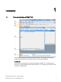

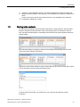
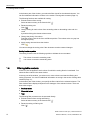

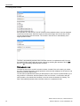
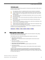
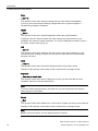


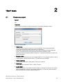
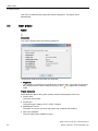

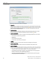

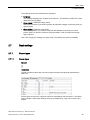
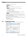

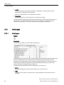
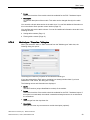
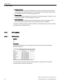


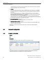

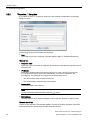
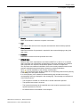
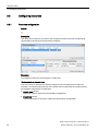
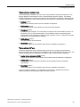

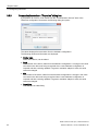

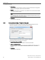
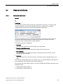
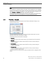
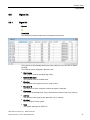


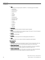

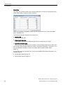
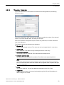


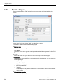
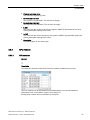


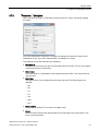
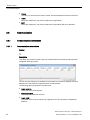
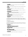
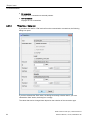

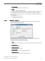


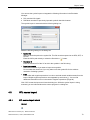
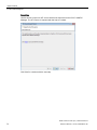

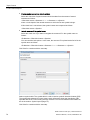
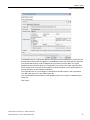
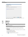
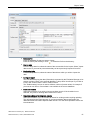


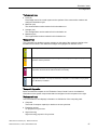

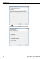
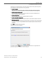
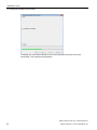


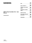


![OverView Control Manager user`s manual - operator [v04]](http://vs1.manualzilla.com/store/data/005659468_1-4c522981c7089838b286d7fbb1120c24-150x150.png)