1
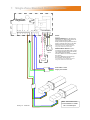
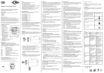
REMOTE SENSOR(s) may be
placed at a max distance of 100m
from the control unit, using
screened 0.75mm² cable.
Wiring should be kept separate
from mains wiring to minimise noise
pick up. Set within Engineers
functions for remote sensor.
REMOTE SWITCH INPUTS should
be connected by 0.75mm² cable.
Max length is 100m.
Low voltage switching inputs to be
normally open (closed circuit to
enable).
Connect to B0 & B1 for remote ON
(ie BMS time control).
Connect to B0 & B2 for remote OFF
(ie door interlock. remote frost etc).
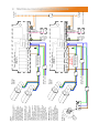
For Master/Slave networks, remote
OFF can be set for individual zones
or total system via the Master.
If individual BMS ON/OFF on
master/slaves systems are required,
set all SmartCom programs to 24
hour and use normally closed
contacts across B0 and B2. Set
engineers variable.
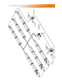
Burners
Zone A
Burners
Zone B
230V 50Hz 1 Pha
Supply via Isolator
41
230V 50Hz 1 Pha
Supply via Isolator
41
40
40
9
25
14
Note: Connection to the
burners MUST be made
via a 3A fused spur.
8
5
6
7
9
25
14
Note: Connection to the
burners MUST be made
via a 3A fused spur.
8
(Master)
5
6
SmartCom Mulitizone
7
(Slave 1)
SmartCom Mulitizone
NEUT
LIVE
NEUT
LIVE
1/L 2/N
1/L 2/N
10
10
eg B.M.S.
Black Bulb
Sensor
eg B.M.S.
To other slave
controllers
To other slave
controllers
Drawing No. : 900296 R4
S/R0S/R1 D0 D1 O0 O1 B1 B0 B2 C2 C0 C1 66 64 20
Black Bulb
Sensor
S/R0S/R1 D0 D1 O0 O1 B1 B0 B2 C2 C0 C1 66 64 20
(REMOTE ON)
(REMOTE ON)
NETWORK. Master-slave (Network)
communication is by screened
twisted pair cable, RS485
compatible such as Belden 9841.
Maximum overall system length of
500m. Connect screen to C0.
NOTE: Diagram shows a master
and ONE slave configuration**.
Wire further slaves in parallel.
(COMMON)
(COMMON)
NOTES:
(REMOTE OFF)
(REMOTE OFF)
3
Multizone Standard Radiant Systems.