1
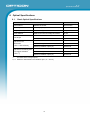
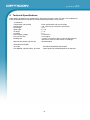
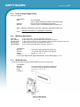
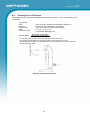
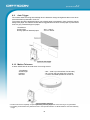
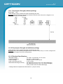
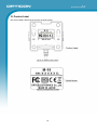
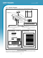
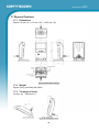
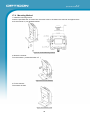
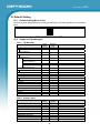
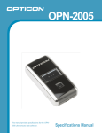
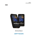
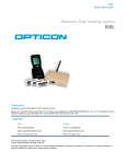
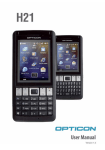
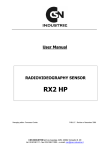
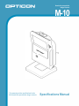
Hands-free presentation
Imager Scanner
M-10
This manual provides specifications for the
M-10 hands-free presentation imager scanner.
Specifications Manual
M-10
Specifications Manual
All information subject to change without notice.
Document History
Model Number:
M-10
Specification Number:
SS13063
Edition:
1st
Original Spec Number:
SS13062
Date:
2014-05-26
Copyright 2014 Opticon. All rights reserved.
This manual may not, in whole or in part, be copied, photocopied, reproduced, translated or converted to any
electronic or machine readable form without prior written consent of Opticon.
Limited Warranty and Disclaimers
PLEASE READ THIS MANUAL CAREFULLY BEFORE INSTALLING
OR USING THE PRODUCT.
Serial Number
A serial number appears on all Opticon products. This official registration number is directly related to the device
purchased. Do not remove the serial number from your Opticon device. Removing the serial number voids the
warranty.
Warranty
Unless otherwise agreed in a written contract, all Opticon products are warranted against defects in materials and
workmanship for two years after purchase. Opticon will repair or, at its option, replace products that are defective
in materials or workmanship with proper use during the warranty period. Opticon is not liable for damages caused
by modifications made by a customer. In such cases, standard repair charges will apply. If a product is returned
under warranty and no defect is found, standard repair charges will apply. Opticon assumes no liability for any
direct, indirect, consequential or incidental damages arising out of use or inability to use both the hardware and
software, even if Opticon has been informed about the possibility of such damages.
Packaging
The packing materials are recyclable. We recommend that you save all packing material to use should you need
to transport your scanner or send it for service. Damage caused by improper packaging during shipment is not
covered by the warranty.
Trademarks
Trademarks used are the property of their respective owners.
Opticon Inc. and Opticon Sensors Europe B.V. are wholly owned subsidiaries of OPTOELECTRONICS Co., Ltd.,
12-17, Tsukagoshi 4-chome, Warabi-shi, Saitama, Japan 335-0002. TEL +81-(0) 48-446-1183; FAX +81-(0) 48446-1184
SUPPORT
USA
Europe
Phone: 800-636-0090
Email: [email protected]
Email: [email protected]
Web: www.opticonusa.com
Web: www.opticon.com
M-10
Specifications Manual
Revision History
Specification No.
Product name
Edition
1st
: SS13063
: M-10
Date
2014/05/26
Page
-
Section
-
Description of Changes
Initial release
M-10
Specifications Manual
Contents
Page
1. Abstract ........................................................................................................................................1
2. Overview ......................................................................................................................................1
3. Basic Specifications ...................................................................................................................2
4. Detailed View ...............................................................................................................................5
5. State Transition ...........................................................................................................................6
5.1.State Transition ......................................................................................................................6
5.2.Current Consumption .............................................................................................................6
6. Electrical Specifications .............................................................................................................7
6.1.USB Power Supply.................................................................................................................7
6.2.AC Adapter Specifications .....................................................................................................7
6.2.1.
6.2.2.
Input Specifications ................................................................................................................... 7
Input Specifications ................................................................................................................... 7
7. Interface Specifications ..............................................................................................................7
7.1.USB........................................................................................................................................7
7.1.1.
7.1.2.
7.1.3.
7.1.4.
USB Interface Specifications..................................................................................................... 7
USB Connector.......................................................................................................................... 8
USB Interface Circuit................................................................................................................. 8
USB Interface Cable.................................................................................................................. 8
7.2.RS-232C ................................................................................................................................9
7.2.1.
7.2.2.
7.2.3.
7.2.4.
7.2.5.
Communication setting.............................................................................................................. 9
Signal Level ............................................................................................................................... 9
D-Sub9pin Assignment.............................................................................................................. 9
D-Sub9pin Assignment............................................................................................................ 10
RS-232C Cable ....................................................................................................................... 10
8. Optical Specifications ...............................................................................................................11
8.1.Basic Optical Specifications .................................................................................................11
8.2.Aiming Pattern......................................................................................................................12
8.3.Scanning Area......................................................................................................................12
9. Technical Specifications ..........................................................................................................13
9.1.Code Test Sample ...............................................................................................................14
9.2.Scanning Area and Depth of Field .......................................................................................15
9.3.Print Contrast Signal (PCS) .................................................................................................16
9.4.Minimum Resolution.............................................................................................................16
9.5.Wide Barcode.......................................................................................................................16
9.6.Pitch, Skew, and Tilt.............................................................................................................17
9.7.Curvature .............................................................................................................................17
9.8.Scanning from LCD Screen .................................................................................................18
9.9.Auto Trigger .........................................................................................................................19
9.10.Motion Tolerance ...............................................................................................................19
10. Environmental Specifications ..................................................................................................20
10.1.Temperature.......................................................................................................................20
10.2.Humidity .............................................................................................................................20
10.3.Ambient Light Immunity......................................................................................................20
M-10
Specifications Manual
10.4.Dust & Water Proof Grade .................................................................................................21
10.5.Cable Strength ...................................................................................................................21
10.6.Cable Bending Strength .....................................................................................................21
10.7.Vibration Strength (without Packing)..................................................................................21
10.8.Vibration Strength (in individual packing)...........................................................................21
10.9.Drop Impact Strength (without packing).............................................................................22
10.10.Drop Impact Strength (in individual packing) ...................................................................22
10.11.Electrical Specifications ...................................................................................................22
11. Regulatory Compliance ............................................................................................................23
11.1.LED Safety .........................................................................................................................23
11.2.EMC ...................................................................................................................................23
12. RoHS...........................................................................................................................................23
13. Reliability ...................................................................................................................................23
14. Precautions ................................................................................................................................23
14.1.Shock .................................................................................................................................23
14.2.Temperature Conditions.....................................................................................................23
14.3.Foreign Materials ...............................................................................................................23
14.4.Other ..................................................................................................................................23
15. Product Label ............................................................................................................................24
16. Packing Specifications .............................................................................................................25
16.1.Individual Packaging ..........................................................................................................25
16.1.1. USB Type ................................................................................................................................ 25
16.1.2. RS-232C Type......................................................................................................................... 26
16.2.Collective Packaging..........................................................................................................27
17. Physical Features ......................................................................................................................28
17.1.Dimensions ........................................................................................................................28
17.2.Weight ................................................................................................................................28
17.3.Tilt Angle of Stand..............................................................................................................28
17.4.Mounting Method ...............................................................................................................29
18. Default Setting ...........................................................................................................................30
18.1.Default Setting Menu Code ................................................................................................30
18.2.Supported Symbologies .....................................................................................................30
18.2.1.
18.2.2.
18.2.3.
18.2.4.
1D Barcodes............................................................................................................................ 30
Postal Codes ........................................................................................................................... 30
GS1 Databar, Composite Code............................................................................................... 31
2D Codes................................................................................................................................. 31
18.3.Other Default......................................................................................................................32
18.4.USB-HID Default ................................................................................................................32
18.5.USB-USB Default...............................................................................................................32
18.6.RS-232C Default ................................................................................................................32
19. Accessories ...............................................................................................................................33
19.1.AC Adapter Specifications .................................................................................................33
19.2.AC Adapter Mechanical Drawing .......................................................................................33
M-10
Specifications Manual
1. Abstract
This manual provides specifications for the M-10 hands-free presentation imager scanner.
2. Overview
The M-10 is a hands-free imager scanner that enables high speed presentation scanning of standard
linear (1D) and 2D symbologies. Main features of the M-10 are as follows:
• Comfortable reading
The scanner ensures extremely high-speed and stress-free reading just by presenting a
target code in front of it. It is also capable of fast response without being affected by hand
movement and a light or dark environment.
• Compact and stylish design
Stylish, ultra-compact and space-saving design that easily fits any desk, work space or
retail counter. The scanner can be tilted forward up to 60 degrees that allows a user to scan
a code in various ways.
• Aiming
A single green LED aiming line that is emitted during code detection and scanning can help
the uses find the position where a target code should be presented.
• Handheld scanning
The scanner also can be used as a handheld scanner by using a trigger switch at the head
of scanner. Its thin and lightweight body (approx. 250 g) makes it easy to hold and reduce
the physical burden on the users.
• Editing function
A new function “Data Editing Program” captures up to 16 codes on multiple images simultaneously
in one go. Output editing process, such as GS1 format, also can be set easily.
• Reading from LCD screen
The scanner can read 1D and 2D codes displayed on LCD screens.
• Various interfaces
Three types of interfaces, USB-HID, USB-COM and RS-232C, are supported.
• RoHS compliance
The M-10 is a RoHS compliant product.
Note: Refer to “M-10 User’s Manual” for supported codes and commands.
1
M-10
Specifications Manual
3. Basic Specifications
Item
Specification
Note
Control
Section
Interf
ace
Optical Section
CPU
32-bit RISC
SDRAM
256 M bits (2 M × 4 Banks × 32 Bits )
Flash ROM
16 M bits (1 M × 16 Bits) Flash Memory
RS-232C
300 bps ~ 115200 bps
USB
USB2.0 Full Speed 12 Mbps (HID/COM)
Scanning method
WVGA CMOS Area sensor (Mono)
Frame rate: 60 fps
Scanning light source
2 Red LEDs
LED Reflector
Aiming and auto trigger
activation light source
1 Green LED
Effective pixels
0.36 million pixels (H: 752 x V: 480)
Field of view
(Vertical x Horizontal)
0 mm
50 mm
100 mm
150 mm
: 48 x 31 mm
: 85 x 54 mm
:122 x 78 mm
:165 x 105 mm
View angle
Horizontal
Vertical
: about 40.6°
: about 26.4°
Symbologies
UPC-A, UPC-E, UPC-E1, UPC-A Add-on ,
UPC-E Add-on, EAN-13, EAN-8, EAN-13
Add-on/EAN-8 Add-on, JAN-8, JAN-13, Code
39, Tri-Optic, NW-7, Industrial 2 of 5,
Interleaved 2 of 5, Code 93, Code 128,
GS1-128, S-Code, MSI/Plessey, UK/Plessey,
TELEPEN, Matrix 2 of 5, IATA, Code 11,
Intelligent Mail Barcode, POSTNET, PLANET,
Netherlands KIX Code, UK Postal (Royal
mail), Australian Postal, Japanese Postal,
Korean Postal Authority code, Chinese Post
Matrix 2 of 5
1D
Supported 1D Symbologies
Postal
Default :9600bps
Minimum resolution
Code 39
Curvature
Radius ≧ 20 mm (12-digit 13mil UPC/EAN)
Motion tolerance
Code 39
Depth of field
(mm)
: 0.127 mm
Possible to read: Code 39 with 100 mm width
and resolution 0.2mm (DOF: 95 mm)
Possible to read: 13mil 100%UPC/EAN moving
at 2 m/s (DOF: 65 mm)
Wide barcode
Resolution 0.127 (5mil)
0 ~ 140
Resolution 0.2 (7.9mil )
10 ~ 120
100%UPC/EAN Resolution 0.33 (13mil)
0 ~ 170
GS1 DataBar
Symbologies
Minimum resolution (mm)
GS1 DataBar, GS1 DataBar Limited, GS1
DataBar Expanded, GS1 DataBar Composite,
GS1-128 Composite, EAN Composite , UPC
Composite
GS1 DataBar
: 0.169 (6.7mil)
Composite Code
: 0.169 (6.7mil)
2
PCS 0.9
35 ~ 60
Resolution 0.254 (10mil)
Code 128
Typical Value
PCS 0.9
M-10
Specifications Manual
Item
Specification
Supported 2D Symbologies
Symbologies
Minimum resolution (mm)
PDF417
Depth of field
(mm)
QR Code
DataMatrix
PDF417, MicroPDF417, Codablock F, QR
Code , Micro QR Code, DataMatrix (ECC 0 140 / ECC 200), MaxiCode, Aztec Code,
Chinese Sensible Code
PDF417
: 0.169 (6.7mil)
QR Code
: 0.169 (6.7mil)
DataMatrix
: 0.212 (8.4mil)
Resolution (0.169)
25 ~ 70
Resolution (0.254)
0 ~ 120
Resolution (0.212)
35 ~ 55
Resolution (0.381)
0 ~ 120
Resolution (0.254)
30 ~ 85
Note
Disable Code 128
when Codablock F is
enabled.
PCS 0.9
Common
Pitch : ±50°
Scan angle
Skew : ±50°
Tilt
: 360°
Imager
Minimum PCS
0.3 or more
Image data format
Windows Bitmap, JPEG
Shades of gray
1024, 256, 16, 2
Range of output image
Select top/bottom (row) and left/right (column)
Resolution of output image
Full,1/2, 1/4
Interface of output image
RS-232C, USB-COM
USB-COM
( Full speed )
RS-232C
(Baud rate: 115.2 kbps)
Baud rate
Range of operating voltage
Power
Current consumption
(USB)
Temperature
Environmental Specifications
Humidity
Ambient light
immunity
Operating
MRD: 32% or more
About 3 sec
Resolution: Full
About 40 sec
4.5 ~ 5.5 V: USB
5.4 ~ 6.6 V: RS-232C (D-Sub9pin)
(external power supply )
Reading Peak
420 mA (Max)
Reading Ave.
250 mA (Typ)
Standby
150 mA (Typ)
Auto trigger sleep
110 mA (Typ)
Non Operation
48 mA (Typ)
0 ~ 40°C
-40 ~ 70°C
Operating
5 ~ 90% (no condensing, no frost)
Storage
5 ~ 90% (no condensing, no frost)
Sunlight
Vibration
Drop
Dust & Water Proof Grade
RS-232C (D-Sub9pin)
External power supply:
Dedicated AC adapter
6.0 V ±5%
USB 5.0V
AC adapter: 0 ~ 40°C
Storage
Fluorescent
Black spot may appear
on image, however, it
does not affect the
scanning performance.
10,000 lx or less
100,000 lx or less
10 Hz ~ 100 Hz, acceleration of 19.6 m/s2, 60
minutes per cycle, repeat once in each X, Y
and Z-direction
Drop 3 times, at each 5 faces (right, left, front,
back and top), from a height of 1.5 m onto a
concrete surface.
IEC/EN 60529 protection level :IP 52
3
* Excluding the part
where the interface
cable is attached
M-10
Specifications Manual
Item
Specification
Note
Regulatory
Peak Wavelength:
624 nm
For residential,
commercial and lightindustrial environments
LED safety
IEC 62471-1:2006 Exempt Risk Group
EMI/RFI
VCCI / EN55022 / FCC Class-B
Product safety
CE Marking
Electromagnetic compatibility
(EMC)
EN55024 (EN61000-6-1) Class-B
For residential,
commercial and lightindustrial environments
No
destruction
No
malfunction
15 kV (Apply static electricity 50 times to the
surface of the scanner)
Contact discharge (direct / indirect): ±6 kV
Air discharge (direct):±8 kV
Condition:
IEC:61000-4-2
compliant
Frequency
80 ~ 1000 MHz
Level
3 V/m
AM
80% (AM)
Voltage
Alternating-current input cable: ±1 kV
Pulse
5 / 50 ns (Tr / Tw)
Frequency
5 kHz
Pulse
1.2 / 50 ns (Tr / Th)
ESD immunity
Radiofrequency
electromagnetic
field. Amplitude
modulation
Fast transient
Immunity Test
Surge
Radiofrequency
common mode
Power
frequency
magnetic field
Voltage dip,
momentary
voltage drop,
fluctuation
Voltage
From L to P : ±2 kV (closed-loop voltage)
From L to L : ±1 kV (closed-loop voltage)
Frequency
0.15 ~ 80 MHz
Level
3V
AM
80% (AM)
Frequency
50 and 60 Hz
Level
3 A/m
Dip 1
Drop 30%, 0.5 cycles
Dip 2
Drop 60%, 5 cycles
Momentary
drop
Drop > 95%, 250 cycles
Physical
Features
Weight
Approx. 250g
External Power Supply
Model name
SFP0602000P-PSE
Output
Condition:
IEC61000-4-5
compliant
Condition:
IEC61000-4-8
compliant
72 × 70 × 139 (WDH mm)
Input
Condition:
IEC61000-4-4
compliant
Condition:
IEC61000-4-6
compliant
Dimensions
Voltage
range
Supply
current
Voltage
range
Maximum
current
Condition:
IEC61000-4-3
compliant
AC 90 ~ 265 V
0.5 A (max)
5.7 ~ 6.3 V
2.0 A (max)
4
Condition:
IEC61000-4-11
compliant
Excluding the interface
cable
Accessories:
conversion plug
M-10
Specifications Manual
4. Detailed View
2
1
3
4
Figure 1: Detailed View of M-10
No
1
Name
Scan Window
Trigger Switch
2
Status LED
3
Buzzer Holes
4
Stand
Description
A window to which codes are presented.
A trigger switch to read codes for use as a handheld scanner
1. Press the trigger switch once, then a green single aiming line lights up.
2. Position the single aiming line over the code and press the trigger switch
again to start reading.
The operating statuses are indicated by blue color different brightness.
Light blue:
Indicates the scanner being in standby state.
Bright blue:
indicates a successful read of codes
Holes through where a sound comes out from a built-in buzzer.
Stands to adjust the angle of the scanner. Adjustable range:
Forward:60°Backward: 15°
5
M-10
Specifications Manual
5. State Transition
5.1.
State Transition
Power ON
Tr
a
to ns i
N tio
on n
Tr
-O co
an
pe mm
s
ra a
to itio
tio nd
n
O
pe co
n
ra mm
tio a
n nd
Non-Operation
Press the trigger switch
Aiming
Transition time to
Auto trigger sleep
(Default :1 minute)
Standby
Aiming time
(Default :3 seconds)
[Auto trigger]
Auto Trigger Sleep
Scanning completes
or
Time out
s
es
Pr
Detect target
e
th
g
tri
w
rs
ge
t
De
et
rg
ta
t
ec
itc
h
Read
Figure 2: State Transition
• Read
The scanner is reading a code with red illumination turned on.
• Standby
The scanner is detecting a target code with green aiming light turned on. The scanner starts
reading when the code is presented in front of it.
• Auto Trigger Sleep
The scanner detects a target code with green aiming light turned off. The green aiming light may
turn on temporarily when there is a change in the background. The green aiming light turns on in
a dark place.
• Aiming
A single line of bright green aiming light is turned on by pressing the trigger switch. When the
aiming line is positioned over the target code and the trigger switch is pressed again, the scanner
starts reading the code.
• Non-operation
The scanner does not perform the reading operation. This mode is supported only when the
command communications (USB-COM or RS-232C) are available.
5.2.
Current Consumption
Conditions
Min.
Typ.
USB :5V,
Max.
T=25°C
Unit
-
-
250
420
mA
-
-
150
mA
Configured
(default: 1 min)
-
110
mA
Configured
Non-Operation current
48
Note: Refer to “M-10 User’s Manual” for supported operation and commands.
mA
Item
Read current
Standby current
Auto trigger sleep current
6
M-10
Specifications Manual
6. Electrical Specifications
6.1.
USB Power Supply
Power supply
Current consumption
: 500 mA High-Power
: 420 mA ( max ) during reading operation
: 150 mA ( typ ) in standby
* The current consumption was measured at 25°C.
6.2.
AC Adapter Specifications
For RS-232C (D-Sub 9pin) model
6.2.1.
Input Specifications
Power supply voltage
Power supply frequency
Maximum current
6.2.2.
: AC 90 ~ 265 V
: 47 ~ 63 Hz
: 0.5 A ( max )
Input Specifications
Output voltage
Power ripple
: 6.0 V ±5% / Output current: 0 ~ 2.0 A ( max )
: 100 mV p-p ( max, rated load )
7. Interface Specifications
The M-10 supports four types of interfaces; USB-HID, USB-COM and RS-232C.
7.1.
USB
The USB interface models have two specifications: HID (Human Interface Device Class) and COM
(Communication Device Class). With USB-COM model, VCP (Virtual Communication Port) allows
virtual serial communication and the commands can be transmitted from the host computer.
* Multi byte character data or images can be transmitted via USB-COM interface.
7.1.1.
USB Interface Specifications
Power supply
Speed
Interface
: 500mA (High-Power).
: USB2.0 Full speed ( 12 Mbps )
: USB-HID / USB-COM (VCP)
* The USB model is bus powered and no AC adapter is required.
* Images cannot be transmitted via the USB-HID interface.
* Multi byte character data can be transmitted via USB-HID interface with settings.
* Make sure to connect to a High-power bus (500 mA max) USB terminal.
7
M-10
Specifications Manual
7.1.2.
USB Connector
Pin No.
Signal name
1
V bus
2
Data ( - )
3
Data ( + )
4
GND
Front view
Figure 3: USB Plug (A)
7.1.3.
USB Interface Circuit
Figure 4: Interface Circuit (USB)
USB Interface Cable
φ4.8
7.1.4.
10
1
4
1
2100+100
-0
Figure 5: USB Interface Cable
8
M-10
Specifications Manual
7.2.
RS-232C
The RS-232C interface has a specification for connecting to the host: D-Sub9pin.
7.2.1.
Communication setting
Baud rate
Data length
Parity bits
Stop bits
: 300 ~ 115200 bps
: 7 / 8 bits
: No / Even / Odd parity
: 1 / 2 bit
* Multi byte character data or images can be transmitted via RS-232C interface.
7.2.2.
Signal Level
Signal names are based on the signals transmitted from the scanner to the host.
Voltage(V)
Signal Name
IN/OUT
Mark
Space
TxD
OUT
-5 ~ -15
+5 ~ +15
RxD
IN
-3 ~ -15
+3 ~ +15
RTS
OUT
-5 ~ -15
+5 ~ +15
CTS
IN
-3 ~ -15
+3 ~ +15
7.2.3.
D-Sub9pin Assignment
Pin No.
Signal Name
Note
1
( NC )
NC
2
TxD
3
RxD
4
-
5
GND
6
-
7
CTS
8
RTS
9
( NC )
NC
Case
FG
Shield
Connect to pin 6
Connect to pin 4
Figure 6: RS-232C D-Sub9pin Connector
9
M-10
Specifications Manual
7.2.4.
D-Sub9pin Assignment
Figure 7: RS-232C D-Sub 9pin Circuit
Connector
: D-Sub 9pin, female
Power supply : EIAJ RC5320A (voltage classification 2) jack
7.2.5.
RS-232C Cable
Figure 8: Cable (RS-232C D-Sub 9pin)
10
M-10
Specifications Manual
8. Optical Specifications
8.1.
Basic Optical Specifications
Item
Characteristics
Scan method
CMOS area sensor
Monochrome
Effective pixels
(Column) × (Row)
752 × 480 (WVGA)
Image capture speed
Frame rate (*1)
60 fps
Focal distance
Distance from the front edge of scanner
65 mm
Horizontal
Approx. 40.6°
Vertical
Approx. 26.4°
Red LED
-
Peak wavelength
617 nm
Maximum radiation output (*3)
15000 mcd
Green LED
-
Peak wavelength
528 nm
Maximum radiation output (*4)
18700 mcd
View angle
Light source for
illumination
(LED × 2 with reflector)
Light source for aiming and
auto trigger activation
(LED × 1)
*1
*2, *3
The fastest seed of image capture
Reference value based on the datasheet (25°C, IF = 50 mA ).
11
M-10
Specifications Manual
8.2.
Aiming Pattern
The aiming is used for the following purpose:
1. Light source to indicate the appropriate reading range
2. Light source for auto trigger operation
The aiming specifications are as follows:
- An optical axis of imaging field of view and the center of horizontal aiming width coincide at a
distance of L=50±20 mm from the front edge of the scanner.
- The horizontal aiming width to the horizontal width of imaging filed of view at a distance of L=60
mm is 80%±10%.
Figure 9: Aiming Pattern and Imaging Range
8.3.
Scanning Area
The range is ±5% from the following values.
L: Distance from the front edge
[mm]
of scanner
H: Horizontal reading area
[mm]
V: Vertical reading area
[mm]
0
50
100
150
48
85
122
165
31
54
78
105
12
M-10
Specifications Manual
9. Technical Specifications
Code reading is performed by positioning the aiming light over the center of a code. The conditions for
technical specifications are as follows, unless otherwise specified in each section.
<Conditions>
Temperature and humidity
Ambient light
Pitch angle
Skew angle
Tilt angle
Curvature
Power supply voltage
PCS (1D and 2D)
Reading test
Barcode test sample (1D and 2D)
<Barcode test sample>
1D codes
GS1 Databar, stacked codes, 2D codes
: Room temperature and room humidity
: 100 ~200 lx (on the surface of a barcode)
: α= 0°
: β = 15°
: γ = 0°
:R=∞
: 3.3 and 5.0 V
: 0.9 or higher
: 1 read in 2 seconds or less. Accept the performance
with 90% or more success rate for 10 readings.
: Specified below
OPTOELECTRONICS test samples
Labels printed by a dedicated printer for barcode
13
M-10
Specifications Manual
9.1.
Code Test Sample
1 D Barcodes
<Code 39>
Resolution
0.127 mm (5mil)
0.20 mm (7.9mil)
0.254 mm (10mil)
Symbology
PCS
Size (mm)
32 × 10
100 × 10
32.5 × 10
No. of Digits
15
31
7
Code 39
0.9
<Code 128>
Resolution
0.20 mm (7.9mil)
Symbology
Code 128
PCS
0.9
Size (mm)
42 × 10
No. of Digits
16
<UPC/EAN>
Resolution
0.330 mm (13mil)
Symbology
100% UPC/EAN
PCS
0.9/0.3
Size (mm)
31.5 × 25.0
No. of Digits
12/13
Symbology
Limited
Limited-Composite
PCS
0.9
0.9
Size (mm)
12 × 1.5
12 × 3.0
No. of Digits
14
26
Error Correction
PCS
No. of Character
Level-3
0.9
Size (mm)
23 × 10
35 × 15
Error Correction
PCS
No. of Character
M
0.9
Size (mm)
5×5
6×6
11 × 11
Model
PCS
No. of Character
ECC200
0.9
Size (mm)
5×5
GS1 Databar / Composite
<GS1-limited>
Resolution
0.169 mm (6.7mil)
0.169 mm (6.7mil)
2 D Codes
<PDF417>
Resolution
0.169 mm (6.7mil)
0.254 mm (10mil)
<QR Code: Model-2>
Resolution
0.169 mm (6.7mil)
0.212 mm (8.4mil)
0.381 mm (15mil)
<Data Matrix>
Resolution
0.212 mm (8.4mil)
0.254 mm (10mil)
Note: The size is outline dimensions excluding quiet zone.
14
6×6
58
44
40
M-10
Specifications Manual
9.2.
Scanning Area and Depth of Field
0
50
100
150
[ Unit : mm ]
0.127(5mil)
35
Code 39
0.254(10mil)
0
100%
UPC/EAN
140
0.20(7.9mil)
10
Code 128
60
120
0.33(13mil)
0
0.169(6.7mil)
25
PDF417
70
0.254(10mil)
0
170
120
0.212(8.4mil)
35
QR Code
0.381(15mil)
0
Data Matrix
55
30
0.254(10mil)
120
80
Figure 10: Scanning Area and Depth of Field
15
M-10
Specifications Manual
9.3.
Print Contrast Signal (PCS)
PSC 0.3 or higher
<Conditions>
MRD
Distance
Barcode
: 32% and higher
(70% or higher reflectivity of white bar and quiet zone)
: 60 mm from the front edge of the scanner
: 0.33mm PCS: 0.3 UPC/EAN specified in Section 9.1.
MRD = Minimum reflectance of white bar - Maximum reflectance of black bar
PCS =
9.4.
Reflectance of white bar-Reflectance of black bar
Reflectance of white bar
Minimum Resolution
1D Code
GS1-Databar
Stacked Code
2D QR Code
2D DataMatrix
: 0.127 mm (5 mil) Code 39 specified in Section 9.1
: 0.169 mm (6.7 mil) GS1 Databar-Limited specified in Section 9.1
: 0.169 mm (6.7 mil) PDF417, GS1 Databar-Limited Composite specified in Section 9.1
: 0.169 mm (8.4 mil) OR Code specified in Section 9.1
: 0.212 mm (8.4 mil) Data Matrix specified in Section 9.1
<Conditions>
Barcode
: The above codes specified in Section 9.1
Distance
: 40 mm from the front edge of the scanner
Angle
: α = 0°, β =+15°, γ = 0°
Curvature
:R=∞
For the pitch angle and tilt angle measurement, set the skew angle β = +15°
9.5.
Wide Barcode
Code 39 with width of 100 mm and resolution of 0.2 mm can be read.
<Conditions>
Barcode
Distance
Angle
Curvature
: 0.20 mm Code 39 specified in Section 9.1
: 95 mm from the front edge of the scanner
: α = 0°, β =+15°, γ = 0°
:R=∞
Figure 11: Wide Barcode
16
M-10
Specifications Manual
9.6.
Pitch, Skew, and Tilt
Pitch
Skew
Tilt
: α = ± 50°
: β = ± 50°
: γ = 360°
<Conditions>
Barcode
: 0.33 mm UPC/EAN specified in Section 9.1
Distance
: 65 mm from the front edge of the Scanner
Curvature
:R=∞
For the pitch angle and tilt angle measurement, set the skew angle β = +15°
Figure 12: Pitch, Skew, and Tilt
9.7.
Curvature
0.33 mm UPC/EAN
<Conditions>
Barcode
Distance
Angle
: R ≧ 20 mm
: 0.33 mm UPC /EAN specified in Section 9.1
: 45 mm from the front edge of the scanner
: α = 0°, β =+15°, γ = 0°
Figure 13: Curvature
* The reading characteristics may deteriorate due to the specular reflection of LED illumination when the
reflectivity is high.
17
M-10
Specifications Manual
9.8.
Scanning from LCD Screen
Codes displayed on LCD screens (brightness of white part 30 cd/m2 or more, contrast ratio 100:1)
can be read.
<Conditions>
Code
Distance
Ambient light
Angle
LCD screen type
Contrast ratio =
: Code for 0.381 mm QR Code specified in Section 9.1
: 65 mm from the front edge of the scanner
: 100 lx or less (on the surface of a barcode)
: α = 0°, β =+15°, γ = 0°
: Transmissive (backlight) TFT
Brightness of white parts
Brightness of black parts
* The barcode resolution is the value when displayed on the LCD screen.
* The width of barcode element is an integral multiple of pixel width of LCD screen.
* The reading characteristics may deteriorate due to the specular reflection of LED illumination
when the reflectivity is high.
Figure 14: Reading from LCD screen
18
M-10
Specifications Manual
9.9.
Auto Trigger
The scanner starts scanning automatically when it detects a change in brightness that occurs when
a barcode label is presented in front of it.
The scanner should be triggered when a gray-colored paper is presented in front of a black-colored
background paper.The scanner should also be triggered when a black-colored paper is presented in
front of a gray-colored background paper.
<Conditions>
Ambient light
Moving speed of detected paper
: 500 ~ 1000 lx
: 2 m/s or slower
Figure 15: Auto Trigger
9.10. Motion Tolerance
0.33mm UPC/EAN can be read when it is moving at 2m/s.
<Conditions>
Ambient light
Distance
Barcode
: 500 ~ 1000 lx (on the surface of a barcode)
: 65 mm from the front edge of the scanner
: 0.33mm UPC/EAN specified in Section 9.1
Figure 16: Motion Tolerance
* The above shows the capability of capturing/scanning a moving target and 100% scanning is not guaranteed.
* The reading characteristics may deteriorate due to the specular reflection of LED illumination when the reflectivity
is high.
19
M-10
Specifications Manual
10. Environmental Specifications
10.1. Temperature
Operating Temperature
Storage Temperature
<Conditions>
Barcode
Distance
Angle
Reading test
: - 0 ~ 40 °C
: -40 ~ 70 °C
: 0.33 mm UPC/EAN specified in Section 9.1
: 65 mm from the front edge of the scanner
: α = 0°, β =+15°, γ = 0°
: Read at intervals of 300 ms
10.2. Humidity
Operating Humidity
Storage Humidity
<Conditions>
Barcode
Distance
Angle
: 5 ~ 90% RH (no condensation, no frost)
: 5 ~ 90% RH (no condensation, no frost)
: 0.33 mm UPC/EAN specified in Section 9.1
: 65 mm from the front edge of the scanner
: α = 0°, β =+15°, γ = 0°
10.3. Ambient Light Immunity
Scanning performance is guaranteed when the illuminance on a barcode surface is between zero
and the following values:
Incandescent Light
Fluorescent Light
Sunlight
<Conditions>
Barcode
Distance
Angle
: 10,000 lx
: 10,000 lx
: 100,000 lx
: 0.33 mm UPCEAN specified in Section 9.1
: 130 mm from the front edge of the scanner
: α = 0°, β =+15°, γ = 0°
Figure 17: Ambient Light Immunity
Note: Scanning performance is guaranteed as far as the direct ambient light or specular reflection from the
illumination LED does not enter the light receiving section of the M-10.
20
M-10
Specifications Manual
10.4. Dust & Water Proof Grade
IEC/EN 60529 Protection Level : IP52
10.5. Cable Strength
There shall be no sign of malfunction after the following cable strength test.
Cable Strength Test: Affix the scanner to an immovable object and pull it using a force of 24.5 N
(2.5 kgf static loading) for 1 second. Repeat this 20 times continuously.
10.6. Cable Bending Strength
There shall be no sign of malfunction after the following cable bending test.
Cable Bending Test: Add a load of 4.9 N (500 gf) to a cable and bend it at an angle of 60° to both
right and left. Repeat this 100000 times continuously.
Figure 18: Cable Bending
10.7. Vibration Strength (without Packing)
There shall be no sign of malfunction after the following vibration test.
Vibration test: Increase the frequency of the vibration from 10 ~ 100 Hz at an accelerated velocity
of 19.6 m/s2 (2.0 G) for 30 minutes (60 minutes per cycle) in the non-operating state. Repeat this in
each X, Y and Z direction.
10.8. Vibration Strength (in individual packing)
There shall be no sign of malfunction after the following vibration test.
Vibration test: Increase the frequency of the vibration from 10 ~ 100 Hz at an accelerated velocity
of 19.6 m/s2 (2.0 G) for 30 minutes (60 minutes per cycle) in individually packaged state. Repeat this
in each X, Y and Z direction.
21
M-10
Specifications Manual
10.9. Drop Impact Strength (without packing)
Drop height : 1.5m
There shall be no sign of malfunction after the following drop test.
Drop test: Drop the scanner three times (15 times in total), at each 5 face, from a height of 1.5m
onto a concrete floor as shown below.
Concrete floor
Figure 19: Drop Test
10.10. Drop Impact Strength (in individual packing)
There shall be no sign of malfunction after the following drop test.
Drop test: Drop an individually packaged scanner 10 times in total, at any of 1 corner, 3 edges, and
6 faces, from a height of 1m onto a concrete floor.
10.11. Electrical Specifications
Withstand Voltage
Insulation Resistance
Current Leakage
Power Line Noise Immunity
Electrostatic Discharge Immunity
: AC 1500 V / 60 seconds, 10 mA or less
: DC 500 V, 2 MΩ or higher
: 250 μA or less / AC 250 V 60 Hz
: ±1 kV or lower
: No destruction found (± 15 kV, air or direct discharge)
: No malfunction found (± 10 kV, air or direct discharge)
: ±6 kV (contact, direct or indirect discharge)
* Testing method is compliant with IEC-61000-4-2. (150 pF, 330 Ω)
22
M-10
Specifications Manual
11. Regulatory Compliance
11.1. LED Safety
IEC 62471-1:2006 Exempt Risk Group
11.2. EMC
EN55022
EN55024
FCC Part 15 Subpart B Class B
This device complies with part 15 of the FCC Rules. Operation is subject to the following two
conditions: ( 1 ) this device may not cause harmful Interference, and ( 2 ) this device must accept
any interference received, including interference that may cause undesired operation.
VCCI Class B
This is a Class B product, to be used in a domestic environment, based on the Technical
Requirement of the Voluntary Control Council for Interference from Information Technology
Equipment (VCCI). If this is used near a radio or television receiver in a domestic environment, it
may cause radio interference.
12. RoHS
The M-10 is compliant with RoHS.
RoHS: The restriction of the use of certain hazardous substances in electrical and electronic
equipment, 2011/65/EU
13. Reliability
MTBF (Mean Time Between Failures)
50,000 hours
Note: The reliability of the M-10 is guaranteed as far as it is operated under normal operating conditions in the
range of advised operating temperature and without excessive electrical or mechanical shock.
14. Precautions
Handle this product carefully. Do not deliberately subject it to any of the following.
14.1. Shock
• Do not throw or drop the scanner outside the specified height.
• Do not place heavy objects on the cables.
14.2. Temperature Conditions
• Do not use the scanner at temperatures outside the specified range.
• Do not pour boiling water on the scanner.
• Do not forcibly bend the cables at low temperatures.
14.3. Foreign Materials
• Do not subject the scanner to chemicals.
14.4. Other
• Do not disassemble this product.
• Do not place the product near a radio or a TV receiver, as the scanner may cause reception
problems.
• The scanner may be damaged by voltage drops.
23
M-10
Specifications Manual
15. Product Label
The product label is affixed to the scanner as shown below.
Figure 20: Product Label Position
Figure 21: Enlarged View of Label
24
M-10
Specifications Manual
16. Packing Specifications
16.1. Individual Packaging
16.1.1. USB Type
Approx. 245 mm ( W ) × 110 mm ( D ) × 84 mm ( H ) ( External dimensions )
The M-10 without cable
Protection bag
QUICK START GUIDE(ENG)
Put a USB cable on the top of the bag
Wrap protection bag
Individual packaging box
【原産国表示】~country of origin~
中国生産(produced in China)=MADE IN CHINA
日本生産(produced in Japan)=MADE IN JAPAN
QUICK START GUIDE(ENG)
Display for the serial-No.
from『 000001 』to 『 099999 』
Same number as the product.
Number of six digits.
*Continuous Number.
BAR CODE LABEL for BOX
(3A0002)
Mo del No .
MADE IN JAPAN
MODEL NEME
M-10-USB-BLK
S pec No .
*UF1M10D*
*バーコード*
It em No.
*12241*
Se ri al No.
* △ △ △ △ △ △*
Figure 22: Individual Packaging USB Type
25
Qu antity
Ro
1
M-10
Specifications Manual
16.1.2. RS-232C Type
Approx. 245 mm ( W ) × 110 mm ( D ) × 84 mm ( H ) ( External dimensions )
The M-10 without cable
Protection bag
QUICK START GUIDE(ENG)
Put a RS-232C cable on the top of the bag
Pactic BAG
Wrap the protection bag
Individual packaging box
Put AC-Adapter & Plugs
*①&② are one product.AC Adapter(Helms-Man)
:SFP0602000P-PSE/VER.2
*AC Adapter and the plugs are changed to the new plastic bags.
【原産国表示】~country of origin~
中国生産(produced in China)=MADE IN CHINA
日本生産(produced in Japan)=MADE IN JAPAN
QUICK START
GUIDE(ENG)
Display for the serial-No.
from『 000001 』to 『 099999 』
Same number as the product.
Number of six digits.
*Continuous Number.
BAR CODE LABEL for BOX
(3A0002)
Mo del No .
MADE IN JAPAN
MODEL NEME
M-10-RS232C-BLK
S pec No .
*UF1M10B*
*バーコード*
It em No.
*12241*
Se ri al No.
* △ △ △ △ △ △*
Figure 23: Individual Packaging RS-232C Type
26
Qu antity
Ro
1
M-10
Specifications Manual
16.2. Collective Packaging
Approx. 600 mm ( W ) × 525 mm ( D ) × 290 mm ( H ) ( External dimensions ) 30sets
Individual packaging box
ROW
列
①
②
③
④
⑤
⑥
⑦
⑧
⑨
⑩
Carton Box:
Packaged 30 sets into the box
①
⑥
②
⑦
Order
S /Nの of
順序
1
4
7
10
13
16
19
22
25
28
~ 3
~ 6
~ 9
~1 2
~1 5
~1 8
~2 1
~2 4
~2 7
~3 0
③
⑧
④
⑨
⑤
⑩
1
33sets
段入り
2
3
【原産国表示】~country of origin~
中国生産(produced in China)=MADE IN CHINA
日本生産(produced in Japan)=MADE IN JAPAN
B : Missing Serial Number Label:
Attach this label when there are more than 3 labels of which
serial numbers are out of order (not in a correct sequence).
A : Barcode Serial Label for Packaging Box:
Stick the labels on both front and back side of the box.
(3C0006)
UNIVERSAL
Prod uct
(3C0007)
C/No.
△△
UNIVERSAL
MADE IN JAPAN
△△
MADE IN JAPAN
M-10-xxxx-BLK
M-10-USB-BLK
MODEL名
PO#
Missing Serial Number
* △ △△△- △△ *
Spec#JPN
C/No.
*UF1M10D*
3
バーコード
Spec#EUR
Missing Q'ty △△
*
△ △ △ △ △ △
*
*
△ △ △ △ △ △
*
*
△ △ △ △ △ △
*
*
△ △ △ △ △ △
*
*
△ △ △ △ △ △
*
*
△ △ △ △ △ △
*
*
△ △ △ △ △ △
*
*
△ △ △ △ △ △
*
*
△ △ △ △ △ △
*
*
△ △ △ △ △ △
*
4
バーコード
5
Spec#USA
*M10BU1S-00*
バーコード
Q'ty
6
S/N(from)
7
*000001*
* △△*
8
S/N(to)
△△/ △ △△
*000▲ ▲▲*
9
Missing Serial Number Missing Q'ty △
1
1 0
* △△ △△ △△ *
1 1
2
* △△ △△ △△ *
1 2
ROM-Ver.
BA01J △ △
Shipping Date
20△△/△△/△△
Ro
OPTOELECTRONICS CO .,LTD.
OPTOELECTRON ICS CO.,LTD.
Figure 24: Collective Packaging
Note: ‘Ro mark’ on the trays and the boxes for the product indicates that the product is RoHS
compliant, which is declared by Optoelectronics Co., Ltd.
27
M-10
Specifications Manual
17. Physical Features
17.1. Dimensions
Approx. 76 mm ( W ) × 70 mm ( D ) × 139.5 mm ( H )
Figure 25: Mechanical Drawing
17.2. Weight
Approx. 250 g (excluding the cable)
17.3. Tilt Angle of Stand
Forward : 60°
Backward :15°
Figure 26: Tilt Angle of Stand
28
M-10
Specifications Manual
17.4. Mounting Method
1. Install the mounting screws.
Insert the specified size of screws into the screw holes in the bottom the scanner and tighten them
to fix the scanner in your desired location.
Figure 27: Screw Mounting Position
2. Mount the scanner.
Turn the scanner. (counterclockwise 18°)
Figure 28: Scanner Rotation
3. Fix the scanner.
The scanner is fixed.
Figure 29: Scanner Fixed
29
M-10
Specifications Manual
18. Default Setting
18.1. Default Setting Menu Code
The M-10 is set to default settings by reading the following menu label regardless of the interface
types.
Default
@MENU_OPTO@ZZ@BAP@ZZ@OTPO_UNEM@
18.2. Supported Symbologies
18.2.1. 1D Barcodes
Code type
UPC
UPC Add-on 2
UPC Add-on 5
EAN(JAN)
EAN Add-on 2
EAN Add-on 5
EAN-13
EAN-13 Add-on 2
EAN-13 Add-on 5
EAN-8
EAN-8 Add-on 2
EAN-8 Add-on 5
Code 39
Tri-Optic
Codabar
Industrial 2of 5
Interleaved 2of 5
S-Code
Code 128
Code 93
IATA
MSI/Plessey
UK/Plessey
Telepen
Code 11
Matrix 2 of 5
Read
Setting
○
Minimum
length
-
○
-
Remarks
○
○
○
○
○
○
○
1
2
5
6
5
1
1
5
3
2
1
1
5
○
○
○
Not transmit ST/SP
Not transmit ST/SP
Not transmit ST/SP
GS1 conversion (setting required)
18.2.2. Postal Codes
Code type
Chinese Post Matrix 2 of 5
Korean Postal Authority
Intelligent Mail Barcode
POSTNET
PLANET
Japan Postal
Netherlands KIX Code
UK Postal (Royal mail)
Australian Postal Code
Read
Setting
Minimum
length
-
30
Remarks
M-10
Specifications Manual
18.2.3. GS1 Databar, Composite Code
Read
setting
Code type
GS1 DataBar
・GS1 DataBar Omnidirectional
・GS1 DataBar Truncated
・GS1 DataBar Stacked
・GS1 DataBar Stacked Omnidirectional
GS1 DataBar Limited
GS1 DataBar Expanded
・GS1 DataBar Expanded
・GS1 DataBar Expanded Stacked
GS1-DataBar Composite
・CC-A
・CC-B
・Limited CC-A
・Limited CC-B
・Expanded CC-A
・Expanded CC-B
GS1-128 Composite
・CC-A
・CC-B
・CC-C
EAN Composite
・EAN-13 CC-A
・EAN-13 CC-B
・EAN-8 CC-A
・EAN-8 CC-B
UPC Composite
・UPC-A CC-A
・UPC-A CC-B
・UPC-E CC-A
・UPC-E CC-B
Remarks
○
GS1 conversion (setting required)
○
○
○
GS1 conversion (setting required)
○
GS1 conversion (setting required)
GS1 conversion (setting required)
GS1 conversion (setting required)
18.2.4. 2D Codes
Code type
Default
PDF417
Remarks
○
Micro PDF417
Codablock F
QR Code
○
Micro QR
○
Data Matrix (ECC 200)
○
Data Matrix (ECC 000-140)
Aztec Code
○
Aztec Runes
Chinese-sensible code
Maxi Code
31
GS1 conversion (setting required)
GS1 conversion (setting required)
M-10
Specifications Manual
18.3. Other Default
Item
Read mode
Extended read time
Buzzer duration
Buzzer tone
Startup buzzer
Buzzer loudness
Good read LED indicator duration
Added suffix value
Multiple read reset time
Auto trigger detection sensitivity
Transition time to auto trigger sleep
Data buffering
Default Setting
Auto trigger
Disable (Auto)
50ms
2.65 kHz
Enable
Max (100%)
200 ms
CR
400ms
High
1 min
Buffered mode
18.4. USB-HID Default
Item
Default Setting
Keyboard language
Inter-character delay
USA
No delay
18.5. USB-USB Default
Item
Description
USB2.0 Full Speed
500 mA
065A
A002
CDC-ACM
Baud rate
Power supply
Vender ID
Product ID
Standards
* It is necessary to install Opticon USB Driver to a host.
18.6. RS-232C Default
Item
Default Setting
9600 bps
No parity
8 bits
1 bit
No handshake
Baud rate
Parity bits
Data length
Stop bits
Handshaking
32
M-10
Specifications Manual
19. Accessories
19.1. AC Adapter Specifications
The M-10 with RS-232C interfaces are shipped with a dedicated AC adapter “Universal AC Adapter
Kit.” Plug connectors can be changed for each region. Refer to 19.2 for the detailed view.
Item
Specifications
Model Name
SFP0602000P-PSE
Dimensions
47.5 x 28.0 x 75.0 (WDH mm)
DC Output Cable Length
1.8 m
Voltage Range
AC 90 ~ 265 V
Input Spec
Supply Current
0.5 A max
Voltage Range
5.7 ~ 6.3 V
Output Spec
Maximum Current
2 A max
Operating Temperature
0 ~ 40°C
19.2. AC Adapter Mechanical Drawing
Figure 30: AC Adapter (input side)
The polarity of the center of DC jack is plus (+).
Figure 31: AC Adapter (output side: DC jack)
33