1
SERIES IOS-330 I/O SERVER MODULE
16-BIT HIGH DENSITY ANALOG INPUT MODULE
___________________________________________________________________________________________
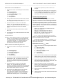
Timer Prescaler Register (Read/Write, 03H)
The Timer Prescaler register can be written with an 8-bit value
to control the interval time between conversions.
Timer Prescaler Register
MSB
15
14
13
12
11
10
09
LSB
08
This 8-bit number divides an 8 MHz clock signal. The clock
signal is further divided by the number held in the Conversion
Timer Register. The resulting frequency can be used to generate
periodic triggers for precisely timed intervals between conversions.
The Timer Prescaler has a minimum allowed value
restriction of 28 hex or 40 decimal. A Timer Prescaler value of
less then 40 (decimal) will result in an empty Mailbox Register
buffer. This minimum value corresponds to a conversion interval
of 5 sec which translates to the maximum conversion rate of 200
KHz. Although the board will operate at the 200 KHz conversion
rate, conversion accuracy will be sacrificed.
The formula used to calculate and determine the desired
Timer Prescaler value is given in the Conversion Timer section
which immediately follows this section.
Read or writing to this register is possible via 16-bit or 8-bit
data transfers. A 16-bit data transfer will implement simultaneous
access to the Interrupt Vector and Timer Prescaler registers. The
Timer Prescaler register contents are cleared upon reset.
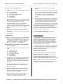
Conversion Timer Register (Read/Write, 04H)
The Conversion Timer Register can be written to control the
interval time between conversions. Read or writing to this register
is possible with either 16-bit or 8-bit data transfers. This register’s
contents are cleared upon reset.
Conversion Timer Register
MSB
LSB
15 14 13 12 11 10 09 08
07 06 05 04 03 02 01 00
This 16-bit number is the second divisor of an 8 MHz. clock
signal and is used together with the Timer Prescaler Register to
derive the frequency of periodic triggers for precisely timed
intervals between conversions.
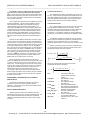
The interval time between conversion triggers is generated by
cascading two counters. The first counter, the Timer Prescaler, is
clocked by an 8 MHz. clock signal. The output of this clock is
input to the second counter, the Conversion Timer, and the output
is used to generate periodic trigger pulses. The time period
between trigger pulses is described by the following equation:
TimerPrescaler ConversionTimer
The maximum period of time which can be programmed to
occur between conversions is (255 65,535) 8 = 2.0889
seconds. The minimum time interval which can be programmed to
occur is
(40 1) 8 = 8 sec. This minimum of 8 sec is defined by the
minimum conversion time of the hardware but does sacrifice
conversion accuracy. To achieve specified conversion accuracy a
minimum conversion time of 15 sec is recommended (see the
specification chapter for details regarding accuracy).
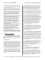
Start Channel Value Register (Read/Write, 06H)
The Start Channel Value register can be written with a 5-bit
value to select the first channel that is to be converted once
conversions have been triggered. All channels between the start
and end channel values are converted. A single channel can be
selected by writing the desired channel value in both the Start and
End Channel Value registers.
The Start Channel Value register can be read or written with 8bit data transfers. In addition, the Start Channel Value register can
be simultaneously accessed with the End Channel Value via a 16bit data transfer. The unused bits are zero when read. The
register contents are cleared upon reset.
Start Channel Value Register
Unused
Start Channel Value
07 06 05
04
03
02
01
00
After running data conversions are halted, the internal
hardware pointers are reinitialized to the start channel value. Thus
when conversions are started again, the first channel converted is
defined by the Start Channel Value register.
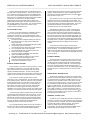
End Channel Value Register (Read/Write, 07H)
The End Channel Value register can be written with a 5-bit
value to indicate the last channel in a sequence to be converted.
When scanning, all channels between and including the start and
end channels are converted. A single channel can be selected by
writing the desired channel value in both the Start and End
Channel Value registers.
The End Channel Value register can be read or written with 8bit data transfers. In addition, the End Channel Value register can
be simultaneously accessed with the Start Channel Value with a
16-bit data transfer. The unused data bits are zero when read.
The register contents are cleared upon reset.
End Channel Value Register
Unused
End Channel Value
15 14 13
12
11
10
09
08
New Data Registers (Read Only, 08H to 0BH)
= T in sec
8
Where: T = time period between trigger pulses in microseconds.
Timer Prescaler can be any value between 40 and 255
decimal.
Conversion Timer can be any value between 1 and
65,535 decimal.
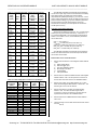
The New Data registers can be read to determine which
channels of the Mailbox buffer contain new converted data. A set
bit in the New Data register indicates that the Mailbox buffer,
corresponding to the channel of the set bit, contains new
converted data. A set New Data register bit is cleared upon a read
of its corresponding Mailbox buffer.
-8Acromag, Inc. Tel:248-295-0310 Fax:248-624-9234 Email:[email protected] http://www.acromag.com