1
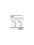
OPERATING INSTRUCTIONS AND SPECIFICATIONS NI 9871 4-Port, RS485/RS422 Serial Module This document describes how to use the National Instruments 9871 and includes specifications and pin assignments for the NI 9871. Visit ni.com/info and enter rdsoftwareversion to determine which software you need for the modules you are using. For information about installing, configuring, and programming the system, refer to the system documentation. Visit ni.com/info and enter cseriesdoc for information about C Series documentation. Note The safety guidelines and specifications in this document are specific to the NI 9871. The other components in your system may not meet the same safety ratings and specifications. Refer to the documentation for each component in your system to determine the safety ratings and specifications for the entire system. NI 9871 Operating Instructions 2 ni.com Safety Guidelines Do not operate the NI 9871 in a manner not specified in the user manual or operating instructions. Product misuse can result in a hazard. You can compromise the safety protection built into the product if the product is damaged in any way. If the product is damaged, return it to National Instruments for repair. Caution This icon denotes that the component may be hot. Touching this component may result in bodily injury. Hot Surface Safety Guidelines for Hazardous Locations The NI 9871 is suitable for use in Class I, Division 2, Groups A, B, C, D, T4 hazardous locations; Class I, Zone 2, AEx nA II T4 and Ex nA II T4 hazardous locations; and nonhazardous locations only. Follow these guidelines if you are installing the NI 9871 in a potentially explosive environment. Not following these guidelines may result in serious injury or death. Do not disconnect I/O-side wires or connectors unless power has been switched off or the area is known to be nonhazardous. Caution © National Instruments 3 NI 9871 Operating Instructions Do not remove modules unless power has been switched off or the area is known to be nonhazardous. Caution Substitution of components may impair suitability for Class I, Division 2. Caution For Zone 2 applications, install the CompactRIO system in an enclosure rated to at least IP 54 as defined by IEC 60529 and EN 60529. Caution For Zone 2 applications, install a protection device between the RS232 signal cables and the NI 9871 RJ-50 jacks (ports 1–4). The device must prevent the RS232 signal-to-signal or signal-to-COM voltage from exceeding 35 V if there is a transient overvoltage condition. Caution For Zone 2 applications, install a protection device between the external power supply and the NI 9871 Vsup and COM pins. The device must prevent the Vsup-to-COM voltage from exceeding 39 V if there is a transient overvoltage condition. Caution NI 9871 Operating Instructions 4 ni.com Special Conditions for Safe Use in Europe This equipment has been evaluated as Ex nA IIC T4 equipment under DEMKO Certificate No. 07 ATEX 0626664X. Each module is marked II 3G and is suitable for use in Zone 2 hazardous locations. Special Guidelines for Marine Applications Some modules are Lloyd’s Register (LR) Type Approved for marine (shipboard) applications. To verify Lloyd’s Register certification for a module, visit ni.com/certification and search for the LR certificate, or look for the Lloyd’s Register mark on the product label. In order to meet the EMC requirements for marine applications, install the module in a shielded enclosure with shielded and/or filtered power and input/output ports. In addition, take precautions when designing, selecting, and installing measurement probes and cables to ensure that the desired EMC performance is attained. Caution © National Instruments 5 NI 9871 Operating Instructions Wiring the NI 9871 The NI 9871 has four RJ-50 receptacles that provide connections for four RS485/RS422 devices. Table 1. RS485/RS422 Port Pinout RJ50 Jack 1 2 3 4 5 6 7 8 9 10 * NC TXD– TXD+ RTS– CTS– RXD– RXD+ RTS+ CTS+ COM RJ-50 Pin Signal Name* 1 No Connect 2 TXD– 3 TXD+ 4 RTS– 5 CTS– 6 RXD– 7 RXD+ 8 RTS+ 9 CTS+ 10 GND These signals are shared by all four RJ-50 connectors on the NI 9871. NI 9871 Operating Instructions 6 ni.com The cables included with your kit convert the RJ-50 pinout to the standard NI pinout, as shown in Table 2. Table 2. Pin Assignments for RS485/RS422 DB-9 Male Connector Connector 6 7 8 9 © National Instruments 1 2 3 4 5 Pin Signal 1 GND 2 CTS+ 3 RTS+ 4 RXD+ 5 RXD– 6 CTS– 7 RTS– 8 TXD+ 9 TXD– 7 NI 9871 Operating Instructions You must connect an external power supply to the NI 9871. This power supply provides the power for the RS485/RS422 transceivers on the module. You can use the included female four-position pigtail to connect to an external voltage source. Figure 1 lists the connections between an external voltage source (of +8 V to +28 V) and the NI 9871. To ensure the specified EMC performance, do not connect the power input to a d.c. mains supply or to any supply requiring a connecting cable longer than 30 m (100 ft.). A d.c. mains supply is a local d.c. electricity supply network in the infrastructure of a certain site or building. Caution NI 9871 Operating Instructions 8 ni.com 2 4 1 3 1 VSUP 2 VSUP 3 COM 4 COM Figure 1. Four-Position External Power Connector Figure 2 shows the method of power connection to the NI 9871 module. Attach an isolated power supply to the Vsup and COM terminals using the included pigtail. © National Instruments 9 NI 9871 Operating Instructions V+ V– Any 8 - 28 V Isolated Power Supply Red (+) Black (–) NI P/N 198159-XX: Female Microfit Pigtail Figure 2. Powering the NI 9871 from an Isolated Power Source Figure 3 shows how to use the optional y-adapter (available at ni.com/serial) to connect power to more than one module using the same power source. One y-adapter is needed for each additional module. Ensure that the power supply can handle maximum power requirements for all modules connected. NI 9871 Operating Instructions 10 ni.com Caution All connections must be made before power is applied. NI P/N 198159-XX: Female Microfit Pigtail V+ V– Any 8 - 28 V Isolated Power Supply Red (+) Black (–) NI P/N 198303-XX: Male Microfit Y-Adapter Figure 3. Powering Multiple Modules from a Single Power Supply © National Instruments 11 NI 9871 Operating Instructions RS485 Bus Topology and Termination Refer to Figure 4 and Figure 5 for an overview of 4-wire and 2-wire RS485 bus topologies and termination. Slave 1 MASTER Tx Tx Rx Slave 2 Tx Rx Slave n Tx Rx 120 Ω 120 Ω 120 Ω 120 Ω Rx Figure 4. 4-Wire Full-Duplex Multidrop Network Using Terminating Resistors Slave 1 MASTER Tx Slave 2 Tx Rx Slave n Tx Rx Rx Tx 120 Ω 120 Ω Rx Figure 5. 2-Wire Multidrop Network Using Terminating Resistors RS485 terminators are available at ni.com/serial. NI 9871 Operating Instructions 12 ni.com RS485 Transceiver Control Refer to Table 3 for a listing of TX and RX enable conditions for the different RS485 transceiver control modes. Table 3. Transceiver Control Pin Conditions 2-Wire Enable 4-Wire DTR/Echo DTR/No Echo Auto TX On DTR DTR TX RX On On DTR# TX# NI 9871 Hardware Overview The NI 9871 has four independent RS485/RS422 ports that are isolated from the other modules in the system. Each port is fully compatible with the ANSI/EIA/TIA-485 standard. © National Instruments 13 NI 9871 Operating Instructions Sleep Mode (CompactRIO Only) You can enable sleep mode for the CompactRIO system in software. In sleep mode, the system consumes less power and may dissipate less heat. Typically, when a system is in sleep mode, you cannot communicate with the modules. Refer to the Specifications section for more information about power consumption and thermal dissipation. Specifications The following specifications are typical for the range –40 to 70 °C unless otherwise noted. Maximum baud rate.......................... 3.6864 Mbps Maximum module throughput .......... 1.28 Mbps Maximum cable length ..................... 1.2 km (4,000 ft.) Data line ESD protection (human body model)......................... ±15 kV MTBF ............................................... 514,016 hours at 25 °C; Bellcore Issue 6, Method 1, Case 3, Limited Part Stress Method NI 9871 Operating Instructions 14 ni.com Note Contact NI for Bellcore MTBF specifications at other temperatures or for MIL-HDBK-217F specifications. Power Requirements Power consumption from chassis Active mode ............................... 0.5 W max Sleep mode ................................. 50 μW max Thermal dissipation (at 70 °C) Active mode ............................... 1.5 W max Sleep mode ................................. 55 mW max Required external supply voltage range (VSUP) ......................... +8 to +28 VDC Power supply consumption from external supply VSUP Typical ........................................ 1 W Maximum ................................... 3.5 W Physical Characteristics If you need to clean the module, wipe it with a dry towel. Weight............................................... Approx. 153 g (5.4 oz) © National Instruments 15 NI 9871 Operating Instructions Safety Maximum Voltage1 Connect only voltages that are within these limits. RS485/RS422 Port-to-COM............. –8 to +13 VDC max, Measurement Category I VSUP-to-COM ................................... ±28 V max, Measurement Category I Measurement Category I is for measurements performed on circuits not directly connected to the electrical distribution system referred to as MAINS voltage. MAINS is a hazardous live electrical supply system that powers equipment. This category is for measurements of voltages from specially protected secondary circuits. Such voltage measurements include signal levels, special equipment, limited-energy parts of equipment, circuits powered by regulated low-voltage sources, and electronics. Do not connect to signals or use for measurements within Measurement Categories II, III, or IV. Caution 1 The maximum voltage that can be applied or output without creating a safety hazard. NI 9871 Operating Instructions 16 ni.com Isolation Voltages Port-to-earth ground Continuous ................................. 60 VDC, Measurement Category I up to 5,000 m altitude Withstand up to 2,000 m altitude .......... 1000 Vrms, verified by a 5 s dielectric withstand test up to 5,000 m altitude .......... 500 Vrms, verified by a 5 s dielectric withstand test Safety Standards This product meets the requirements of the following standards of safety for electrical equipment for measurement, control, and laboratory use: • IEC 61010-1, EN 61010-1 • UL 61010-1, CSA 61010-1 Note For UL and other safety certifications, refer to the product label or the Online Product Certification section. © National Instruments 17 NI 9871 Operating Instructions Hazardous Locations U.S. (UL) .......................................... Class I, Division 2, Groups A, B, C, D, T4; Class I, Zone 2, AEx nA II T4 Canada (C-UL) ................................. Class I, Division 2, Groups A, B, C, D, T4; Class I, Zone 2, Ex nA II T4 Europe (DEMKO)............................. Ex nA IIC T4 Environmental Refer to the installation instructions for the chassis you are using for more information about meeting these specifications. Operating temperature ...................... –40 to 70 °C Storage temperature .......................... –40 to 85 °C Ingress protection.............................. IP 30 Operating humidity........................... 10 to 90% RH, noncondensing Storage humidity............................... 5 to 95% RH, noncondensing NI 9871 Operating Instructions 18 ni.com Pollution Degree (IEC 60664) .......... 2 Maximum altitude............................. 5,000 m Indoor use only Shock and Vibration To meet these specifications, you must panel mount the CompactRIO system. Operating vibration, random (IEC 60068-2-64) ................ 5 grms, 10 to 500 Hz Operating shock (IEC 60068-2-27)....30 g, 11 ms half sine, 50 g, 3 ms half sine, 18 shocks at 6 orientations Operating vibration, sinusoidal (IEC 60068-2-6) .............. 5 g, 10 to 500 Hz © National Instruments 19 NI 9871 Operating Instructions Electromagnetic Compatibility This product meets the requirements of the following EMC standards for electrical equipment for measurement, control, and laboratory use: • EN 61326 (IEC 61326): Class A emissions; Basic immunity • EN 55011 (CISPR 11): Group 1, Class A emissions • AS/NZS CISPR 11: Group 1, Class A emissions • FCC 47 CFR Part 15B: Class A emissions • ICES-001: Class A emissions Note For the standards applied to assess the EMC of this product, refer to the Online Product Certification section. Note For EMC compliance, operate this product according to the documentation. NI 9871 Operating Instructions 20 ni.com CE Compliance This product meets the essential requirements of applicable European Directives as follows: • 2006/95/EC; Low-Voltage Directive (safety) • 2004/108/EC; Electromagnetic Compatibility Directive (EMC) Online Product Certification Refer to the product Declaration of Conformity (DoC) for additional regulatory compliance information. To obtain product certifications and the DoC for this product, visit ni.com/ certification, search by model number or product line, and click the appropriate link in the Certification column. Environmental Management NI is committed to designing and manufacturing products in an environmentally responsible manner. NI recognizes that eliminating certain hazardous substances from our products is beneficial to the environment and to NI customers. For additional environmental information, refer to the NI and the Environment Web page at ni.com/environment. This page © National Instruments 21 NI 9871 Operating Instructions contains the environmental regulations and directives with which NI complies, as well as other environmental information not included in this document. Waste Electrical and Electronic Equipment (WEEE) EU Customers At the end of the product life cycle, all products must be sent to a WEEE recycling center. For more information about WEEE recycling centers, National Instruments WEEE initiatives, and compliance with WEEE Directive 2002/96/EC on Waste and Electronic Equipment, visit ni.com/environment/weee. ⬉ᄤֵᙃѻક∵ᶧࠊㅵ⧚ࡲ⊩ ˄Ё RoHS˅ Ёᅶ᠋ National Instruments ヺড়Ё⬉ᄤֵᙃ ѻકЁ䰤ࠊՓ⫼ᶤѯ᳝ᆇ⠽䋼ᣛҸ (RoHS)DŽ݇Ѣ National Instruments Ё RoHS ড়㾘ᗻֵᙃˈ䇋ⱏᔩ ni.com/environment/rohs_chinaDŽ (For information about China RoHS compliance, go to ni.com/ environment/rohs_china.) NI 9871 Operating Instructions 22 ni.com Where to Go for Support The National Instruments Web site is your complete resource for technical support. At ni.com/support you have access to everything from troubleshooting and application development self-help resources to email and phone assistance from NI Application Engineers. National Instruments corporate headquarters is located at 11500 North Mopac Expressway, Austin, Texas, 78759-3504. National Instruments also has offices located around the world to help address your support needs. For telephone support in the United States, create your service request at ni.com/support and follow the calling instructions or dial 512 795 8248. For telephone support outside the United States, visit the Worldwide Offices section of ni.com/niglobal to access the branch office Web sites, which provide up-to-date contact information, support phone numbers, email addresses, and current events. © National Instruments 23 NI 9871 Operating Instructions LabVIEW, National Instruments, NI, ni.com, the National Instruments corporate logo, and the Eagle logo are trademarks of National Instruments Corporation. Refer to the Trademark Information at ni.com/trademarks for other National Instruments trademarks. Other product and company names mentioned herein are trademarks or trade names of their respective companies. For patents covering National Instruments products/technology, refer to the appropriate location: Help»Patents in your software, the patents.txt file on your media, or the National Instruments Patent Notice at ni.com/patents. Refer to the Export Compliance Information at ni.com/legal/export-compliance for the National Instruments global trade compliance policy and how to obtain relevant HTS codes, ECCNs, and other import/export data. © 2007–2012 National Instruments. All rights reserved. 372277E-01 Apr12