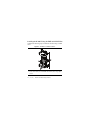
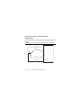
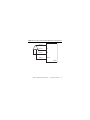
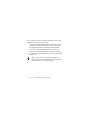
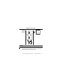
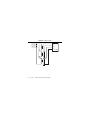
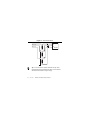
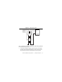
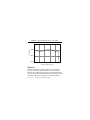
1
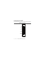
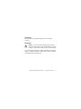
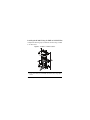
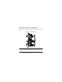
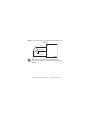
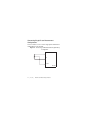
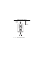
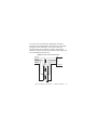
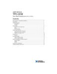
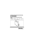
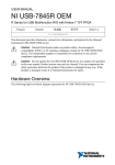
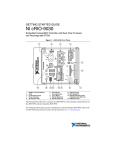
USER MANUAL AND SPECIFICATIONS NI 9242 4-Channel, 250 Vrms, 24-Bit Simultaneous Analog Input Module Français Deutsch ni.com/manuals This document describes how to use the National Instruments 9242 and includes specifications and pin assignments for the NI 9242. Note The safety guidelines and specifications in this document are specific to the NI 9242. The other components in the system might not meet the same safety ratings and specifications. Refer to the documentation for each component in the system to determine the safety ratings and specifications for the entire system. Related Information 2 | NI CompactDAQ & NI CompactRIO Documentation ni.com/info cseriesdoc Chassis Compatibility ni.com/info compatibility Software Support ni.com/info softwareversion Services ni.com/services ni.com | NI 9242 User Manual and Specifications Safety Guidelines Operate the NI 9242 only as described in this manual. Hot Surface This icon denotes that the component may be hot. Touching this component may result in bodily injury. This icon denotes a warning advising you to take precautions to avoid electrical shock. Warning Do not operate the NI 9242 in a manner not specified in this manual. Product misuse can result in a hazard. You can compromise the safety protection built into the product if the product is damaged in any way. If the product is damaged, return it to National Instruments for repair. Caution NI 9242 User Manual and Specifications | © National Instruments | 3 Safety Guidelines for Hazardous Voltages If hazardous voltages are connected to the module, take the following precautions. A hazardous voltage is a voltage greater than 42.4 Vpk or 60 VDC to earth ground. Ensure that hazardous voltage wiring is performed only by qualified personnel adhering to local electrical standards. Caution Do not mix hazardous voltage circuits and human-accessible circuits on the same module. Caution Make sure that devices and circuits connected to the module are properly insulated from human contact. Caution When module terminals are hazardous voltage LIVE (>42.4Vpk/60 VDC), you must ensure that devices and circuits connected to the module are properly insulated from human contact. You must use the NI 9967 connector backshell kit to ensure that the terminals are not accessible. Caution 4 | ni.com | NI 9242 User Manual and Specifications Figure 1 shows the NI 9967 connector backshell. Figure 1. NI 9967 Connector Backshell NI 9242 User Manual and Specifications | © National Instruments | 5 Safety Guidelines for Hazardous Locations The NI 9242 is suitable for use in Class I, Division 2, Groups A, B, C, D, T4 hazardous locations; Class I, Zone 2, AEx nA IIC T4, and Ex nA IIC T4 hazardous locations; and nonhazardous locations only. Follow these guidelines if you are installing the NI 9242 in a potentially explosive environment. Not following these guidelines may result in serious injury or death. Do not disconnect I/O-side wires or connectors unless power has been switched off or the area is known to be nonhazardous. Caution Do not remove modules unless power has been switched off or the area is known to be nonhazardous. Caution Substitution of components may impair suitability for Class I, Division 2. Caution For Division 2 and Zone 2 applications, install the system in an enclosure rated to at least IP 54 as defined by IEC/EN 60529. Caution 6 | ni.com | NI 9242 User Manual and Specifications Special Conditions for Hazardous Locations Use in Europe This equipment has been evaluated as Ex nA IIC T4 Gc equipment under DEMKO 12 ATEX 1202658X. Each module is marked II 3G and is suitable for use in Zone 2 hazardous locations, in ambient temperatures of -40 °C ≤ Ta ≤ 70 °C. If you are using the NI 9242 in Gas Group IIC hazardous locations, you must use the device in an NI chassis that has been evaluated as Ex nC IIC T4, EEx nC IIC T4, Ex nA IIC T4, or Ex nL IIC T4 equipment. Caution The system shall be mounted in an ATEX certified enclosure with a minimum ingress protection rating of at least IP54 as defined in IEC/EN 60529 and used in an environment of not more than Pollution Degree 2. The enclosure must have a door or cover accessible only by the use of a tool. Caution NI 9242 User Manual and Specifications | © National Instruments | 7 Electromagnetic Compatibility Guidelines This product was tested and complies with the regulatory requirements and limits for electromagnetic compatibility (EMC) as stated in the product specifications. These requirements and limits are designed to provide reasonable protection against harmful interference when the product is operated in its intended operational electromagnetic environment. This product is intended for use in industrial locations. There is no guarantee that harmful interference will not occur in a particular installation, when the product is connected to a test object, or if the product is used in residential areas. To minimize the potential for the product to cause interference to radio and television reception or to experience unacceptable performance degradation, install and use this product in strict accordance with the instructions in the product documentation. Furthermore, any changes or modifications to the product not expressly approved by National Instruments could void your authority to operate it under your local regulatory rules. 8 | ni.com | NI 9242 User Manual and Specifications Special Guidelines for Marine Applications Some products are Lloyd’s Register (LR) Type Approved for marine (shipboard) applications. To verify Lloyd’s Register certification for a product, visit ni.com/certification and search for the LR certificate, or look for the Lloyd’s Register mark on the product label. Caution In order to meet the EMC requirements for marine applications, install the product in a shielded enclosure with shielded and/or filtered power and input/output ports. In addition, take precautions when designing, selecting, and installing measurement probes and cables to ensure that the desired EMC performance is attained. NI 9242 User Manual and Specifications | © National Instruments | 9 Connecting the NI 9242 The NI 9242 provides connections for four analog input channels. Figure 2. NI 9242 Pinout 10 | ni.com | AI0 0 AI1 1 AI2 2 Neutral 3 NI 9242 User Manual and Specifications Connector The NI 9242 has a 4-terminal, detachable screw-terminal connector. Backshell Caution For safe operation with hazardous voltages, you must use the NI 9967 Connector Backshell, as shown in Figure 1, with the 4-terminal connector on the NI 9242. You can use the backshell with 12 AWG to 24 AWG wires with the NI 9967. 12 AWG to 14 AWG, 16 AWG, and 18 AWG to 24 AWG require different strain-relief pieces. NI 9242 User Manual and Specifications | © National Instruments | 11 Installing the NI 9967 Using 12 AWG to 14 AWG Wire Complete the following steps to install the NI 9967 using 12 AWG to 14 AWG wires. Figure 3. 12 AWG to 14 AWG Installation 2 1 1 Route wires over the strain-relief piece. 2 Secure strain-relief piece and NI 9967 backshell in place using captive screws. 12 | ni.com | NI 9242 User Manual and Specifications Installing the NI 9967 Using 16 AWG Wire Complete the following steps to install the NI 9967 using 16 AWG wires. Figure 4. 16 AWG Installation 2 1 1 Route wires through the strain-relief pieces. 2 Secure strain-relief piece and NI 9967 backshell in place using captive screws. NI 9242 User Manual and Specifications | © National Instruments | 13 Installing the NI 9967 Using 18 AWG to 24 AWG Wire Complete the following steps to install the NI 9967 using 16 AWG wires. Figure 5. 18 AWG to 24 AWG Installation 2 1 1 Route wires over the strain-relief piece. 2 Secure strain-relief piece and NI 9967 backshell in place using captive screws. 14 | ni.com | NI 9242 User Manual and Specifications Signals The NI 9242 has three AI terminals and a Neutral terminal. You can connect three-phase and single-phase measurement configurations to the NI 9242. The NI 9242 supports standard service levels up to 250 Vrms Line-to-Neutral (L-N) and 400 Vrms Line-to-Line (L-L). You can also connect standard potential transformers to the NI 9242. Note You must use 2-wire ferrules to create a secure connection when connecting more than one wire to a single terminal on the NI 9242. Circuitry Each channel on the NI 9242 provides an independent signal path and ADC. Each terminal has the same input impedance to ground. The NI 9242 returns the voltage between each AI terminal and the Neutral terminal as well as the voltage between the Neutral terminal and the chassis ground. Refer to Figure 6 for a diagram of the equivalent voltages the module returns. NI 9242 User Manual and Specifications | © National Instruments | 15 Figure 6. Internal Circuitry for the NI 9242 AI0 AI0 V AI1 AI1 V AI2 AI2 Neutral V Neutral V GND NI 9242 To ensure that measurements to chassis ground are correct, NI recommends connecting the chassis to earth ground using the chassis grounding screw. Refer to your chassis manual for information about connecting the chassis to earth ground. 16 | ni.com | NI 9242 User Manual and Specifications Connecting Phase Measurements You can connect three-phase measurement configurations and single-phase measurement configurations to the NI 9242. NI recommends using the following phase measurement configurations for typical power distribution networks. Other valid configurations are possible if the connections do not exceed the safety rating of the NI 9242. NI 9242 User Manual and Specifications | © National Instruments | 17 Connecting Three-Phase Measurement Configurations You can connect WYE or delta measurement configurations to the NI 9242. Figure 7. Connecting a 4-Wire WYE Measurement Configuration Phase A AI0 Phase B AI1 AI2 Phase C Neutral Neutral NI 9242 18 | ni.com | NI 9242 User Manual and Specifications Figure 8. Connecting a High-Leg Delta Measurement Configuration Phase A AI0 Phase B AI1 Phase C AI2 Neutral Neutral NI 9242 NI 9242 User Manual and Specifications | © National Instruments | 19 Figure 9. Connecting a 3-Wire Delta Measurement Configuration Phase A AI0 Phase B AI1 Phase C AI2 NI 9242 20 | ni.com | NI 9242 User Manual and Specifications Figure 10. Connecting a Corner Grounded 2-Wire Delta Measurement Configuration Phase A AI0 Phase B AI1 Phase C AI2 NI 9242 Note Corner grounded 2-wire delta measurement configurations support only standard service levels up to 240 Vrms L-L. NI 9242 User Manual and Specifications | © National Instruments | 21 Connecting Single-Phase Measurement Configurations You can connect 3-wire or 2-wire single-phase measurement configurations to the NI 9242. Figure 11. Connecting a 3-Wire Measurement (Split Phase) Configuration AI0 AI1 Neutral NI 9242 22 | ni.com | NI 9242 User Manual and Specifications Figure 12. Connecting a 2-Wire Measurement AI0 Neutral NI 9242 Connecting Potential Transformers You can connect potential transformers to the NI 9242. When measuring voltages using potential transformers, scale the NI 9242 readings with your application software using the transformer ratio to get readings that refer to the primary of the potential transformers. For example, if using a 320:1 ratio potential transformer, multiply the readings by 320. Tip NI 9242 User Manual and Specifications | © National Instruments | 23 Figure 13. 4-Wire WYE-to-WYE (Full) Phase A AI0 Phase B AI1 Phase C AI2 Neutral N NI 9242 24 | ni.com | NI 9242 User Manual and Specifications In a 4-wire WYE-to-WYE (full) configuration, the Neutral terminal on the NI 9242 measures the neutral-to-ground voltage through the bottom transformer. You can use a lower ratio transformer due to the typically low voltages on the Neutral terminal. Ensure that you scale each NI 9242 channel reading with the corresponding transformer ratio. Figure 14. 4-Wire WYE-to-WYE (Partial) Phase A AI0 Phase B AI1 Phase C AI2 Neutral N NI 9242 NI 9242 User Manual and Specifications | © National Instruments | 25 For 4-wire WYE-to-WYE (partial) configurations, follow these guidelines for the best accuracy results. • Connect the Neutral terminal of the NI 9242 to the isolated ground of the potential transformer to reduce noise between the potential transformer ground and the chassis ground. • Connect the Neutral terminal of the NI 9242 as close as possible to the isolated ground of the potential transformer. • Use the L-N voltage measurements the NI 9242 returns as the default value. You can convert L-N voltage measurements to channel-to-earth ground by adding the Neutral terminal measurement to each of the AI channels. Tip 26 | ni.com | NI 9242 User Manual and Specifications Figure 15. Delta-to-Delta Phase A AI0 Phase B AI1 Phase C AI2 NI 9242 1 1 Optional You can use the Neutral channel for any other measurement if the measurement does not exceed the Neutral-to-Earth and L-N input range. Tip NI 9242 User Manual and Specifications | © National Instruments | 27 Figure 16. Delta-to-WYE Phase A AI0 Phase B AI1 Phase C AI2 N NI 9242 28 | ni.com | NI 9242 User Manual and Specifications For delta-to-WYE configurations, follow these guidelines for the best accuracy results. • Connect the Neutral terminal of the NI 9242 to the isolated ground of the potential transformer to reduce noise between the potential transformer ground and the chassis ground. • Connect the Neutral terminal of the NI 9242 as close as possible to the isolated ground of the potential transformer. • Use the L-N voltage measurements the NI 9242 returns as the default value. You can convert L-N voltage measurements to channel-to-earth ground by adding the Neutral terminal measurement to each of the AI channels. Tip NI 9242 User Manual and Specifications | © National Instruments | 29 Figure 17. 3-Wire WYE-to-Delta Phase A AI0 Phase B AI1 Phase C AI2 NI 9242 You can use the Neutral channel for any other measurement if the measurement does not exceed the Neutral-to-Earth and L-N input range. Tip 30 | ni.com | NI 9242 User Manual and Specifications Figure 18. 3-Wire WYE-to-WYE Phase A AI0 Phase B AI1 Phase C AI2 N NI 9242 For 3-wire WYE-to-WYE configurations, follow these guidelines for the best accuracy results. • Connect the Neutral terminal of the NI 9242 to the isolated ground of the potential transformer to reduce noise between the potential transformer ground and the chassis ground. NI 9242 User Manual and Specifications | © National Instruments | 31 • Connect the Neutral terminal of the NI 9242 as close as possible to the isolated ground of the potential transformer. • Use the L-N voltage measurements the NI 9242 returns as the default value. You can convert L-N voltage measurements to channel-to-earth ground by adding the Neutral terminal measurement to each of the AI channels. Tip Converting L-N Measurements to L-L To convert L-N measurements to L-L values, calculate the voltage difference between the AI channels using your application software. Refer to the following equation for an example of converting L-N measurements to L-L. Phase A to Phase B Voltage = AI0 - AI1 where AI0 is the reading from Phase A AI1 is the reading from Phase B 32 | ni.com | NI 9242 User Manual and Specifications Converting L-N Measurements to L-Earth To convert L-N measurements to L-Earth values, add the neutral channel reading to each AI channel reading. Refer to the following equation for an example of converting L-N measurements to L-Earth. Line to Earth = AIx + Neutral where AIx is the analog input channel reading Neutral is the Neutral channel reading NI 9242 User Manual and Specifications | © National Instruments | 33 Wiring for High-Vibration Applications If an application is subject to high vibration, National Instruments recommends that you use ferrules to terminate wires to the detachable screw-terminal connector. Refer to Figure 19 for an illustration of using ferrules. Figure 19. 4-Terminal Detachable Screw-Terminal Connector with Ferrule 34 | ni.com | NI 9242 User Manual and Specifications Understanding NI 9242 Filtering The NI 9242 uses a combination of analog and digital filtering to provide an accurate representation of in-band signals while rejecting out-of-band signals. The filters discriminate between signals based on the frequency range, or bandwidth, of the signal. The three important bandwidths to consider are the passband, the stopband, and the alias-free bandwidth. The NI 9242 represents signals within the passband, as quantified primarily by passband ripple and phase nonlinearity. All signals that appear in the alias-free bandwidth are either unaliased signals or signals that have been filtered by at least the amount of the stopband rejection. Passband The signals within the passband have frequency-dependent gain or attenuation. The small amount of variation in gain with respect to frequency is called the passband flatness. The digital filters of the NI 9242 adjust the frequency range of the passband to match the data rate. Therefore, the amount of gain or attenuation at a given frequency depends on the data rate. Figure 20 shows typical passband flatness for the NI 9242. NI 9242 User Manual and Specifications | © National Instruments | 35 Figure 20. Typical Passband Response of the NI 9242 0.025 Gain (dB) 0.000 –0.025 –0.050 0 0.1 0.2 0.3 0.4 0.5 Frequency/Data Rate (Hz) Stopband The filter significantly attenuates all signals above the stopband frequency. The primary goal of the filter is to prevent aliasing. Therefore, the stopband frequency scales precisely with the data rate. The stopband rejection is the minimum amount of attenuation applied by the filter to all signals with frequencies within the stopband. 36 | ni.com | NI 9242 User Manual and Specifications Alias-Free Bandwidth Any signal that appears in the alias-free bandwidth of the NI 9242 is not an aliased artifact of signals at a higher frequency. The alias-free bandwidth is defined by the ability of the filter to reject frequencies above the stopband frequency, and it is equal to the data rate minus the stopband frequency. Understanding NI 9242 Data Rates The frequency of a master timebase (fM) controls the data rate (fs) of the NI 9242. The NI 9242 includes an internal master timebase with a frequency of 12.8 MHz, but the module also can accept an external master timebase or export its own master timebase. To synchronize the data rate of an NI 9242 with other modules that use master timebases to control sampling, all of the modules must share a single master timebase source. Refer to the software help for information about configuring the master timebase source for the NI 9242. Visit ni.com/info and enter cseriesdoc for information about C Series documentation. NI 9242 User Manual and Specifications | © National Instruments | 37 The following equation provides the available data rates of the NI 9242: f M ÷ 256 fs = -------------------n where n is any integer from 1 to 31. However, the data rate must remain within the appropriate data rate range. Refer to the Specifications section for more information about the data rate range. When using the internal master timebase of 12.8 MHz, the result is data rates of 50 kS/s, 25 kS/s, 16.667 kS/s, and so on down to 1.613 kS/s, depending on the value of n. When using an external timebase with a frequency other than 12.8 MHz, the NI 9242 has a different set of data rates. The NI 9151 R Series Expansion chassis does not support sharing timebases between modules. Note 38 | ni.com | NI 9242 User Manual and Specifications Sleep Mode This module supports a low-power sleep mode. Support for sleep mode at the system level depends on the chassis that the module is plugged into. Refer to the chassis manual for information about support for sleep mode. If the chassis supports sleep mode, refer to the software help for information about enabling sleep mode. Typically, when a system is in sleep mode, you cannot communicate with the modules. In sleep mode, the system consumes minimal power and may dissipate less heat than it does in normal mode. Related Information Power Requirements Specifications The following specifications are typical for the range -40 °C to 70 °C unless otherwise noted. Input Characteristics Scaling coefficient ............................ 59,605 nV/LSB Number of channels.......................... 4 analog input channels NI 9242 User Manual and Specifications | © National Instruments | 39 ADC resolution................................. 24 bits Type of ADC..................................... Delta-Sigma (with analog prefiltering) Sampling mode ................................. Simultaneous Internal master timebase (fM) Frequency ................................... 12.8 MHz Accuracy..................................... ±100 ppm max Data rate range (fs) using internal master timebase Minimum.................................... 1.613 kS/s Maximum ................................... 50 kS/s Data rate range (fs) using external master timebase Minimum.................................... 390.625 S/s Maximum ................................... 51.2 kS/s f M ÷ 256 Data rates1 (fs) ................................... --------------------- , n = 1, 2, …, 31 n 1 The data rate must remain within the appropriate data rate range. Refer to the Understanding NI 9242 Data Rates section for more information. 40 | ni.com | NI 9242 User Manual and Specifications Input voltage range (AIx and Neutral-to-GND, AIx-to-Neutral) Typical ........................................ 500 Vpk Minimum.................................... 497 V Overvoltage withstand ...................... 500 Vrms continuous, 600 Vrms for 10 s Surge withstand ................................ 5 kV (1.2 µs/50 µs) Input coupling................................... DC Input impedance, AIx-to-Ground and Neutral-to-GND ......................... 1 MΩ Table 1. DC and AC Accuracy Percent of Reading (Gain Error) Percent of Range* (Offset Error) Calibrated max (-40 °C to 70 °C) 0.26% 0.14% Calibrated typ (23 °C ±5 °C) 0.05% 0.022% Uncalibrated max (-40 °C to 70 °C) 0.50% 0.26% Uncalibrated typ (23 °C ±5 °C) 0.18% 0.06% Measurement Conditions * Range equals 354 V (250 Vrms × √2) NI 9242 User Manual and Specifications | © National Instruments | 41 Accuracy specifications are valid for L-L, L-N and L-Earth measurements. Note Input noise at 50 kS/s N-Earth and L-Earth................... 2.12 mVrms L-N and L-L1 .............................. 3 mVrms Note When measuring the amplitude of the fundamental frequency over one or several power cycles the noise of the measurement reduces significantly (theoretically with the square root of the number of samples in the acquisition window). Nonlinearity (at 25 °C) ..................... 20 ppm Stability Gain drift .................................... 12.1 ppm/ °C Offset drift .................................. 3.4 mV/ °C 1 The NI 9242 returns L-N and N-Earth values only. Refer to Converting L-N Measurements to L-L and Converting L-N Measurements to L-Earth sections for details on changing the point of reference of the measurement. 42 | ni.com | NI 9242 User Manual and Specifications Post calibration gain match (channel-to-channel, max) Up to 20 kHz .............................. 95 mdB Up to 10 kHz .............................. 44 mdB Up to 3.8 kHz ............................. 30 mdB Phase mismatch (channel-to-channel) ......................... 0.138°/ kHz max Phase mismatch (module-to-module, max) ................. 0.138°/kHz + 360° * fin/ fM Phase nonlinearity (fs = 50 kS/s) 0 kHz to 10 kHz ......................... 0.017° max 0 kHz to 20 kHz ......................... 0.034° max 5 Input delay ........................................ 40 --------- /fs + 1.5 µs 512 Passband Frequency ................................... 0.453 * fs Flatness 0 kHz to 20 kHz ......................... ±50 mdB max 0 kHz to 10 kHz ......................... ±20 mdB max NI 9242 User Manual and Specifications | © National Instruments | 43 Negative phase sequence error at 50 Hz and 60 Hz At 5% unbalance Maximum............................. 0.21% Typical.................................. 0.09% At 1% unbalance Maximum............................. 0.22% Typical.................................. 0.1% Zero phase sequence error at 50 Hz and 60 Hz At 5% unbalance Maximum............................. 0.21% Typical.................................. 0.09% At 1% unbalance Maximum............................. 0.22% Typical.................................. 0.1% Stopband Frequency ................................... 0.547 * fs Rejection..................................... -95 dB Alias-free bandwidth ........................ 0.453 * fs 44 | ni.com | NI 9242 User Manual and Specifications Anti-alias rejection (fS = 50 kS/s) ..... 53 dB -3 dB bandwidth (fs = 50 kS/s).......... 0.49 * fs Crosstalk 60 Hz .......................................... -105 dB 1 kHz .......................................... -79 dB CMRR (fin = 60 Hz).......................... -75 dB SFDR (1 kHz, -60 dBFS).................. -120 dB Total Harmonic Distortion (THD), up to 1 kHz........................................ -100 dB MTBF ............................................... Contact NI for Bellcore MTBF or MIL-HDBK-217F specifications. Power Requirements Power consumption from chassis Active mode ............................... 332 mW max Sleep mode ................................. 50 µW max Thermal dissipation Active mode ............................... 582 mW max Sleep mode ................................. 250 mW max NI 9242 User Manual and Specifications | © National Instruments | 45 Physical Characteristics If you need to clean the module, wipe it with a dry towel. Note For two-dimensional drawings and three-dimensional models of the C Series module and connectors, visit ni.com/dimensions and search by module number. Screw-terminal wiring ...................... 0.511 mm diameter (24 AWG) to 2.053 mm diameter (12 AWG) copper conductor wire with 7 mm (0.28 in.) of insulation stripped from the end Torque for screw terminals ............... 0.5 N · m to 0.6 N · m (4.42 lb · in. to 5.30 lb · in.) Ferrules ............................................. 0.25 mm2 to 2.5 mm2 Weight............................................... 150 g (5.3 oz) 46 | ni.com | NI 9242 User Manual and Specifications Safety Connect only voltages that are within the following limits. Maximum working voltage, channel-to-earth ground Continuous........................................ 250 Vrms, Measurement Category III Division 2 and Zone 2 hazardous locations applications Channel-to-earth ground................... 250 Vrms , Measurement Category III Measurement Category III is for measurements performed in the building installation at the distribution level. This category refers to measurements on hard-wired hardware such as hardware in fixed installations, distribution boards, and circuit breakers. Other examples are wiring, including cables, bus bars, junction boxes, switches, socket outlets in the fixed installation, and stationary motors with permanent connections to fixed installations. Caution Do not connect the NI 9242 to signals or use for measurements within Measurement Categories IV. NI 9242 User Manual and Specifications | © National Instruments | 47 Hazardous Locations U.S. (UL) .......................................... Class I, Division 2, Groups A, B, C, D, T4; Class I, Zone 2, AEx nA IIC T4 Canada (C-UL) ................................. Class I, Division 2, Groups A, B, C, D, T4; Class I, Zone 2, Ex nA IIC T4 Europe (DEMKO) ............................ Ex nA IIC T4 Gc Safety and Hazardous Locations Standards This product meets the requirements of the following standards of safety for electrical equipment for measurement, control, and laboratory use: • IEC 61010-1, EN 61010-1 • UL 61010-1, CSA 61010-1 • EN 60079-0:2009, EN 60079-15:2010 • IEC 60079-0:2007; Ed 5, IEC 60079-15:2010; Ed 4 48 | ni.com | NI 9242 User Manual and Specifications • UL 60079-0: Ed 5, UL 60079-15: Ed 3 • CSA 60075-0:2011, CSA 60079-15:2012 Note For UL and other safety certifications, refer to the product label or the Online Product Certification section. Electromagnetic Compatibility This product meets the requirements of the following EMC standards for electrical equipment for measurement, control, and laboratory use: • EN 61326-1 (IEC 61326-1): Class A emissions; Industrial immunity • EN 55011 (CISPR 11): Group 1, Class A emissions • EN 55022 (CISPR 22): Class A emissions • EN 55024 (CISPR 24): Immunity • AS/NZS CISPR 11: Group 1, Class A emissions • AS/NZS CISPR 22: Class A emissions • FCC 47 CFR Part 15B: Class A emissions • ICES-001: Class A emissions NI 9242 User Manual and Specifications | © National Instruments | 49 Note In the United States (per FCC 47 CFR), Class A equipment is intended for use in commercial, light-industrial, and heavy-industrial locations. In Europe, Canada, Australia and New Zealand (per CISPR 11) Class A equipment is intended for use only in heavy-industrial locations. Note Group 1 equipment (per CISPR 11) is any industrial, scientific, or medical equipment that does not intentionally generates radio frequency energy for the treatment of material or inspection/analysis purposes. Note For EMC declarations and certifications, refer to the Online Product Certification section. CE Compliance This product meets the essential requirements of applicable European Directives as follows: • 2006/95/EC; Low-Voltage Directive (safety) • 2004/108/EC; Electromagnetic Compatibility Directive (EMC) 50 | ni.com | NI 9242 User Manual and Specifications Online Product Certification To obtain product certifications and the Declaration of Conformity (DoC) for this product, visit ni.com/certification, search by module number or product line, and click the appropriate link in the Certification column. Shock and Vibration To meet these specifications, you must panel mount the system. If you are using the NI 9242 with screw terminal, you also must either affix ferrules to the ends of the terminal wires. Operating vibration Random (IEC 60068-2-64)......... 5 grms, 10 Hz to 500 Hz Sinusoidal (IEC 60068-2-6) ....... 5 g, 10 Hz to 500 Hz Operating shock (IEC 60068-2-27).............................. 30 g, 11 ms half sine, 50 g, 3 ms half sine, 18 shocks at 6 orientations NI 9242 User Manual and Specifications | © National Instruments | 51 Environmental Refer to the manual for the chassis you are using for more information about meeting these specifications. Operating temperature (IEC 60068-2-1, IEC 60068-2-2) ..... -40 °C to 70 °C Storage temperature (IEC 60068-2-1, IEC 60068-2-2) ..... -40 °C to 85 °C Ingress protection.............................. IP 40 Operating humidity (IEC 60068-2-56).............................. 10% to 90% RH, noncondensing Storage humidity (IEC 60068-2-56).............................. 5% to 95% RH, noncondensing Pollution Degree ............................... 2 Maximum altitude............................. 5,000 m Indoor use only. 52 | ni.com | NI 9242 User Manual and Specifications Environmental Management NI is committed to designing and manufacturing products in an environmentally responsible manner. NI recognizes that eliminating certain hazardous substances from our products is beneficial to the environment and to NI customers. For additional environmental information, refer to the Minimize Our Environmental Impact Web page at ni.com/environment. This page contains the environmental regulations and directives with which NI complies, as well as other environmental information not included in this document. Waste Electrical and Electronic Equipment (WEEE) EU Customers At the end of the product life cycle, all products must be sent to a WEEE recycling center. For more information about WEEE recycling centers, National Instruments WEEE initiatives, and compliance with WEEE Directive 2002/96/EC on Waste and Electronic Equipment, visit ni.com/environment/ weee. NI 9242 User Manual and Specifications | © National Instruments | 53 ⬉ᄤֵᙃѻક∵ᶧࠊㅵ⧚ࡲ⊩ ˄Ё RoHS˅ Ёᅶ᠋ National Instruments ヺড়Ё⬉ᄤֵᙃ ѻકЁ䰤ࠊՓ⫼ᶤѯ᳝ᆇ⠽䋼ᣛҸ (RoHS)DŽ݇Ѣ National Instruments Ё RoHS ড়㾘ᗻֵᙃˈ䇋ⱏᔩ ni.com/environment/rohs_chinaDŽ (For information about China RoHS compliance, go to ni.com/ environment/rohs_china.) Calibration You can obtain the calibration certificate and information about calibration services for the NI 9242 at ni.com/calibration. Calibration interval ........................... 1 year Worldwide Support and Services The National Instruments website is your complete resource for technical support. At ni.com/support you have access to everything from troubleshooting and application development self-help resources to email and phone assistance from NI Application Engineers. Visit ni.com/services for NI Factory Installation Services, repairs, extended warranty, and other services. 54 | ni.com | NI 9242 User Manual and Specifications Visit ni.com/register to register your National Instruments product. Product registration facilitates technical support and ensures that you receive important information updates from NI. A Declaration of Conformity (DoC) is our claim of compliance with the Council of the European Communities using the manufacturer’s declaration of conformity. This system affords the user protection for electromagnetic compatibility (EMC) and product safety. You can obtain the DoC for your product by visiting ni.com/certification. If your product supports calibration, you can obtain the calibration certificate for your product at ni.com/calibration. National Instruments corporate headquarters is located at 11500 North Mopac Expressway, Austin, Texas, 78759-3504. National Instruments also has offices located around the world. For telephone support in the United States, create your service request at ni.com/support or dial 1 866 ASK MYNI (275 6964). For telephone support outside the United States, visit the Worldwide Offices section of ni.com/niglobal to access the branch office websites, which provide up-to-date contact information, support phone numbers, email addresses, and current events. NI 9242 User Manual and Specifications | © National Instruments | 55 Refer to the NI Trademarks and Logo Guidelines at ni.com/trademarks for more information on National Instruments trademarks. Other product and company names mentioned herein are trademarks or trade names of their respective companies. For patents covering National Instruments products/technology, refer to the appropriate location: Help»Patents in your software, the patents.txt file on your media, or the National Instruments Patent Notice at ni.com/patents. You can find end-user license agreements (EULAs) and third-party legal notices in the readme file for your NI product. Refer to the Export Compliance Information at ni.com/legal/ export-compliance for the National Instruments global trade compliance policy and how to obtain relevant HTS codes, ECCNs, and other import/export data. © 2014 National Instruments. All rights reserved. 376130B-01 Mar14