1
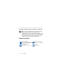
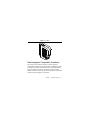
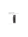
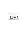
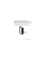
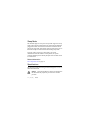
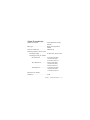
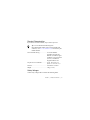
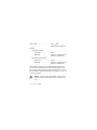
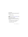
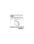
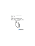
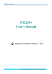
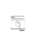
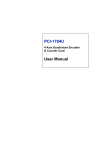
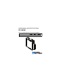
USER MANUAL AND SPECIFICATIONS NI 9482 4-Channel SPST Electromechanical Relay Module Français Deutsch ni.com/manuals This document describes how to use the National Instruments 9482 and includes specifications and pin assignments for the NI 9482. Note The safety guidelines and specifications in this document are specific to the NI 9482. The other components in the system might not meet the same safety ratings and specifications. Refer to the documentation for each component in the system to determine the safety ratings and specifications for the entire system. Related Information 2 | NI CompactDAQ & NI CompactRIO Documentation ni.com/info cseriesdoc Chassis Compatibility ni.com/info compatibility Software Support ni.com/info softwareversion Services ni.com/services ni.com | NI 9482 Safety Guidelines Operate the NI 9482 only as described in these operating instructions. Hot Surface This icon denotes that the component may be hot. Touching this component may result in bodily injury. This icon denotes a warning advising you to take precautions to avoid electrical shock. Warning Do not operate the NI 9482 in a manner not specified in this user manual. Product misuse can result in a hazard. You can compromise the safety protection built into the product if the product is damaged in any way. If the product is damaged, return it to National Instruments for repair. Caution Safety Guidelines for Hazardous Voltages If hazardous voltages are connected to the module, take the following precautions. A hazardous voltage is a voltage greater than 42.4 Vpk or 60 VDC to earth ground. NI 9482 | © National Instruments | 3 Ensure that hazardous voltage wiring is performed only by qualified personnel adhering to local electrical standards. Caution Do not mix hazardous voltage circuits and human-accessible circuits on the same module. Caution Make sure that devices and circuits connected to the module are properly insulated from human contact. Caution When module terminals are hazardous voltage LIVE (>42.4Vpk/60 VDC), you must ensure that devices and circuits connected to the module are properly insulated from human contact. You must use the NI 9927 connector backshell kit to ensure that the terminals are not accessible. Caution 4 | ni.com | NI 9482 Figure 1. NI 9927 Electromagnetic Compatibility Guidelines This product was tested and complies with the regulatory requirements and limits for electromagnetic compatibility (EMC) as stated in the product specifications. These requirements and limits are designed to provide reasonable protection against harmful interference when the product is operated in its intended operational electromagnetic environment. NI 9482 | © National Instruments | 5 This product is intended for use in industrial locations. There is no guarantee that harmful interference will not occur in a particular installation, when the product is connected to a test object, or if the product is used in residential areas. To minimize the potential for the product to cause interference to radio and television reception or to experience unacceptable performance degradation, install and use this product in strict accordance with the instructions in the product documentation. Furthermore, any changes or modifications to the product not expressly approved by National Instruments could void your authority to operate it under your local regulatory rules. To ensure the specified EMC performance, operate this product only with shielded cables and accessories. Caution The I/O port pins of this product can be damaged if subjected to Electrostatic Discharge (ESD). To prevent damage, industry-standard ESD prevention measures must be employed during installation, maintenance, and operation. Caution 6 | ni.com | NI 9482 The I/O port of this product is rated for Measurement Category II; however, it is neither designed nor tested for compliance with the transient immunity requirements for Electrical Fast Transients or lightning Surge, which are normally applied to ports intended for connection to the electrical distribution system. For applications where connection to the electrical distribution system is desired, ensure that the I/O port is provided with appropriate transient protection. Caution NI 9482 | © National Instruments | 7 Connecting the NI 9482 The NI 9482 provides connections for four electromechanical relay channels. Figure 2. NI 9482 Pinout 0 CH0a CH0b CH1a CH1b CH2a CH2b CH3a CH3b NC NC 8 | ni.com | NI 9482 3 0 1 2 3 4 5 6 7 8 9 Connector The NI 9482 has a 10-terminal, detachable screw-terminal connector. Signals Each channel has two interchangeable pins, CHa and CHb, to which you can connect a load. Note You must use 2-wire ferrules to create a secure connection when connecting more than one wire to a single terminal on the NI 9482. LEDs Each channel has an LED that indicates the state of the channel. A channel LED is lit when the channel is on and dark when the channel is off. The LEDs are disabled when the chassis is in sleep mode. Related Information Sleep Mode on page 12 NI 9482 | © National Instruments | 9 Connecting a Load You can connect loads to the NI 9482. Connect the positive lead of the load to CHa or CHb, the ground of the load to the power supply, and the remaining CHa or CHb to the other lead of the power supply. Figure 3. Connecting a Load CHa + or Load NI 9482 CHb – AC When the channel is turned on, the terminal connected to the load drives current or applies voltage to the load. When the channel is off, the terminal does not drive current or apply voltage to the load. 10 | ni.com | NI 9482 Wiring for High-Vibration Applications If an application using the NI 9482 is subject to high vibration, National Instruments recommends that you either use ferrules to terminate wires to the detachable screw-terminal connector or use the NI 9927 backshell kit to protect the connections. Figure 4. Wiring a Screw-Terminal Connector with a Ferrule NI 9482 | © National Instruments | 11 Sleep Mode This module supports a low-power sleep mode. Support for sleep mode at the system level depends on the chassis that the module is plugged into. Refer to the chassis manual for information about support for sleep mode. If the chassis supports sleep mode, refer to the software help for information about enabling sleep mode. Typically, when a system is in sleep mode, you cannot communicate with the modules. In sleep mode, the system consumes minimal power and may dissipate less heat than it does in normal mode. Related Information Power Requirements on page 14 Specifications The following specifications are typical for the range -40 °C to 70 °C unless otherwise noted. Using the NI 9482 in a manner not described in this document may impair the protection the NI 9482 provides. Caution 12 | ni.com | NI 9482 Output Characteristics Number of channels.......................... 4 electromechanical relay channels Relay type ......................................... Single pole single throw (SPST) Power-on output state ....................... Channels off Switching capacity (resistive load) Switching voltage....................... 60 VDC max, 250 Vrms max Switching current, per channel One channel on .................... 2.5 A max at 30 VDC, 1 A max at 60 VDC, 2.5 A max at 250 Vrms Two channels on .................. 2 A max at 30 VDC, 1 A max at 60 VDC, 2 A max at 250 Vrms All channels on .................... 1.5 A max at 30 VDC, 1 A max at 60 VDC, 1.5 A max at 250 Vrms Resistance per channel, channel on......................................... 0.2 Ω NI 9482 | © National Instruments | 13 Switching rate ................................... 1 operation per second Relay release time............................. 10 ms max Relay operate time ............................ 15 ms max Relay bounce time ............................ 3 ms Off state leakage ............................... 10 μA max Life expectancy Mechanical (no load).................. 20,000,000 operations Electrical (connecting to load) ... 100,000 operations MTBF ............................................... Contact NI for Bellcore MTBF or MIL-HDBK-217F specifications Power Requirements Power consumption from chassis Active mode ............................... 580 mW max Sleep mode ................................. 10 mW max Thermal dissipation (at 70 °C) Active mode ............................... 1.5 W max Sleep mode ................................. 10 mW max 14 | ni.com | NI 9482 Physical Characteristics If you need to clean the module, wipe it with a dry towel. For two-dimensional drawings and three-dimensional models of the C Series module and connector, visit ni.com/dimensions and search by the module number. Tip Screw-terminal wiring ...................... 0.511 mm diameter (24 AWG) to 2.053 mm diameter (12 AWG) copper conductor wire with 10 mm (0.39 in.) of insulation stripped from the end Torque for screw terminals ............... 0.5 N · m to 0.6 N · m (4.4 lb · in. to 5.3 lb · in.) Ferrules ............................................. 0.25 mm2 to 2.5 mm2 Weight............................................... 150 g (5.3 oz) Safety Voltages Connect only voltages that are within the following limits. NI 9482 | © National Instruments | 15 CHa-to-CHb...................................... 250 Vrms max, Measurement Category II Isolation Channel-to-channel Continuous ........................... 250 Vrms Withstand ............................. 1,400 Vrms, verified by a 5 s dielectric withstand test Channel-to-earth ground Continuous ........................... 250 Vrms Withstand ............................. 2,300 Vrms, verified by a 5 s dielectric withstand test Measurement Category II is for measurements performed on circuits directly connected to the electrical distribution system. This category refers to local-level electrical distribution, such as that provided by a standard wall outlet, for example, 115 V for U.S. or 230 V for Europe. Caution Do not connect the NI 9482 to signals or use for measurements within Measurement Categories III or IV. 16 | ni.com | NI 9482 Safety Standards This product meets the requirements of the following standards of safety for electrical equipment for measurement, control, and laboratory use: • IEC 61010-1, EN 61010-1 • UL 61010-1, CSA 61010-1 Note For UL and other safety certifications, refer to the product label or the Online Product Certification section. Electromagnetic Compatibility This product meets the requirements of the following EMC standards for electrical equipment for measurement, control, and laboratory use: • EN 61326 (IEC 61326): Class A emissions; Basic immunity • EN 55011 (CISPR 11): Group 1, Class A emissions • AS/NZS CISPR 11: Group 1, Class A emissions • FCC 47 CFR Part 15B: Class A emissions • ICES-001: Class A emissions NI 9482 | © National Instruments | 17 Note In the United States (per FCC 47 CFR), Class A equipment is intended for use in commercial, light-industrial, and heavy-industrial locations. In Europe, Canada, Australia and New Zealand (per CISPR 11) Class A equipment is intended for use only in heavy-industrial locations. Note Group 1 equipment (per CISPR 11) is any industrial, scientific, or medical equipment that does not intentionally generates radio frequency energy for the treatment of material or inspection/analysis purposes. Note For EMC declarations and certifications, refer to the Online Product Certification section. CE Compliance This product meets the essential requirements of applicable European Directives as follows: • 2006/95/EC; Low-Voltage Directive (safety) • 2004/108/EC; Electromagnetic Compatibility Directive (EMC) 18 | ni.com | NI 9482 Online Product Certification To obtain product certifications and the Declaration of Conformity (DoC) for this product, visit ni.com/certification, search by module number or product line, and click the appropriate link in the Certification column. Shock and Vibration To meet these specifications, you must panel mount the system. Operating vibration, sinusoidal (IEC 60068-2-6) .............. 5 g, 40 Hz to 500 Hz; 0.062 in. double amplitude, 10 Hz to 40 Hz Note The shock and vibration rating for the NI 9482 is limited, in comparison to other NI CompactDAQ and CompactRIO devices, due to the mechanical relays on the module. NI 9482 | © National Instruments | 19 Environmental Refer to the manual for the chassis you are using for more information about meeting these specifications. Operating temperature (IEC 60068-2-1, IEC 60068-2-2) ..... -40 °C to 70 °C Storage temperature (IEC 60068-2-1, IEC 60068-2-2) ..... -40 °C to 85 °C Ingress protection NI 9482....................................... IP 30 NI 9482 with screw-terminal connector attached...................... IP 40 Operating humidity (IEC 60068-2-56).............................. 10% to 90% RH, noncondensing Storage humidity (IEC 60068-2-56).............................. 5% to 95% RH, noncondensing Pollution Degree ............................... 2 Maximum altitude............................. 5,000 m Indoor use only. 20 | ni.com | NI 9482 Environmental Management NI is committed to designing and manufacturing products in an environmentally responsible manner. NI recognizes that eliminating certain hazardous substances from our products is beneficial to the environment and to NI customers. For additional environmental information, refer to the Minimize Our Environmental Impact Web page at ni.com/environment. This page contains the environmental regulations and directives with which NI complies, as well as other environmental information not included in this document. NI 9482 | © National Instruments | 21 Waste Electrical and Electronic Equipment (WEEE) EU Customers At the end of the product life cycle, all products must be sent to a WEEE recycling center. For more information about WEEE recycling centers, National Instruments WEEE initiatives, and compliance with WEEE Directive 2002/96/EC on Waste and Electronic Equipment, visit ni.com/environment/weee. ⬉ᄤֵᙃѻક∵ᶧࠊㅵ⧚ࡲ⊩ ˄Ё RoHS˅ Ёᅶ᠋ National Instruments ヺড়Ё⬉ᄤֵᙃ ѻકЁ䰤ࠊՓ⫼ᶤѯ᳝ᆇ⠽䋼ᣛҸ (RoHS)DŽ݇Ѣ National Instruments Ё RoHS ড়㾘ᗻֵᙃˈ䇋ⱏᔩ ni.com/environment/rohs_chinaDŽ (For information about China RoHS compliance, go to ni.com/ environment/rohs_china.) 22 | ni.com | NI 9482 Worldwide Support and Services The National Instruments website is your complete resource for technical support. At ni.com/support you have access to everything from troubleshooting and application development self-help resources to email and phone assistance from NI Application Engineers. Visit ni.com/services for NI Factory Installation Services, repairs, extended warranty, and other services. Visit ni.com/register to register your National Instruments product. Product registration facilitates technical support and ensures that you receive important information updates from NI. A Declaration of Conformity (DoC) is our claim of compliance with the Council of the European Communities using the manufacturer’s declaration of conformity. This system affords the user protection for electromagnetic compatibility (EMC) and product safety. You can obtain the DoC for your product by visiting ni.com/certification. If your product supports calibration, you can obtain the calibration certificate for your product at ni.com/calibration. NI 9482 | © National Instruments | 23 Refer to the NI Trademarks and Logo Guidelines at ni.com/trademarks for more information on National Instruments trademarks. Other product and company names mentioned herein are trademarks or trade names of their respective companies. For patents covering National Instruments products/technology, refer to the appropriate location: Help»Patents in your software, the patents.txt file on your media, or the National Instruments Patent Notice at ni.com/patents. You can find information about end-user license agreements (EULAs) and third-party legal notices in the readme file for your NI product. Refer to the Export Compliance Information at ni.com/legal/export-compliance for the National Instruments global trade compliance policy and how to obtain relevant HTS codes, ECCNs, and other import/export data. © 2013 National Instruments. All rights reserved. 373948B-01 Dec13