1
USER’S MANUAL
CONTENTS
User’s Manual.............................................................................................................................................. 1
Contents....................................................................................................................................................... 2
Notice ........................................................................................................................................................... 3
Introduction ................................................................................................................................................. 4
Aberdeen Contact Information .................................................................................................................. 5
5-Year Warranty Terms and Conditions ................................................................................................... 5
Mission Statement ...................................................................................................................................... 6
Company Background................................................................................................................................ 6
Goals ............................................................................................................................................................ 7
The Aberdeen Advantage........................................................................................................................... 7
Aberdeen Leads Industry with 5-Year Warranty ...................................................................................... 8
Custom Server Solutions Provider ........................................................................................................... 8
References ................................................................................................................................................... 9
Reviews and Awards ................................................................................................................................ 10
Previous Comments from the Experts.................................................................................................... 10
APPENDIX - A XDAS Scalable NAS........................................................................................................ 11
Initial XDAS Administration ..................................................................................................................... 12
Aberdeen XDAS Series RAID Subsystem Hardware Installation Guide.............................................. 16
2
NOTICE
No part of this manual, including the products and software described in it, may be reproduced, transmitted,
transcribed, stored in a retrieval system, or translated into any language in any form or by any means, except
documentation kept by the purchaser for backup purposes, without the express written permission of ABERDEEN
LLC. ("ABERDEEN").
ABERDEEN PROVIDES THIS MANUAL "AS IS" WITHOUT WARRANTY OF ANY KIND, EITHER EXPRESS OR IMPLIED,
INCLUDING BUT NOT LIMITED TO THE IMPLIED WARRANTIES OR CONDITIONS OF MERCHANTABILITY OR FITNESS
FOR A PARTICULAR PURPOSE. IN NO EVENT SHALL ABERDEEN, ITS DIRECTORS, OFFICERS, EMPLOYEES OR
AGENTS BE LIABLE FOR ANY INDIRECT, SPECIAL, INCIDENTAL, OR CONSEQUENTIAL DAMAGES (INCLUDING
DAMAGES FOR LOSS OF PROFITS, LOSS OF BUSINESS, LOSS OF USE OR DATA, INTERRUPTION OF BUSINESS
AND THE LIKE), EVEN IF ABERDEEN HAS BEEN ADVISED OF THE POSSIBILITY OF SUCH DAMAGES ARISING FROM
ANY DEFECT OR ERROR IN THIS MANUAL OR PRODUCT.
Product warranty or service will not be extended if: (1) the product is repaired, modified or altered, unless such
repair, modification of alteration is authorized in writing by ABERDEEN; or (2) the serial number of the product is
defaced or missing.
Products and corporate names appearing in this manual may or may not be registered trademarks or copyrights of
their respective companies, and are used only for identification or explanation and to the owners' benefit, without
intent to infringe.
•
•
•
•
•
•
Aberdeen, Stirling, AberNAS, Backup Monster, TeraBuster, TeraStorus, and XDAS are registered
trademarks of Aberdeen LLC.
Intel, Pentium, and Xeon are registered trademarks of Intel Corporation.
3ware and Escalade are registered trademarks of Applied Micro Circuits Corporation.
Microsoft, Windows, and Windows NT are registered trademarks of Microsoft Corporation.
Adobe and Acrobat are registered trademarks of Adobe Systems Incorporated.
Adaptec is a registered trademark of Adaptec Inc.
For previous or updated manuals, BIOS, drivers, or product release information, contact ABERDEEN at
http://www.Aberdeeninc.com or through any of the means indicated on the following pages.
SPECIFICATIONS AND INFORMATION CONTAINED IN THIS MANUAL ARE FURNISHED FOR INFORMATIONAL USE
ONLY, AND ARE SUBJECT TO CHANGE AT ANY TIME WITHOUT NOTICE, AND SHOULD NOT BE CONSTRUED AS A
COMMITMENT BY ABERDEEN. ABERDEEN ASSUMES NO RESPONSIBILITY OR LIABILITY FOR ANY ERRORS OR
INACCURACIES THAT MAY APPEAR IN THIS MANUAL, INCLUDING THE PRODUCTS AND SOFTWARE DESCRIBED IN
IT.
Copyright © 2004 ABERDEEN LLC. All Rights Reserved.
3
INTRODUCTION
Aberdeen LLC, the Custom Server Solution Provider, has provided an excellent
selection of quality custom computing solutions to the IT professional for more than
a decade. As an innovator of storage solutions Aberdeen has become a one-stop
solution source for the IT Professional.
The computer industry is a continuously evolving marketplace. With a clear vision
of the future, Aberdeen has become a trend setter via its vast technical experience
and industry foresight. Aberdeen is a pioneer in providing customizable rack
mounted servers, backup solutions and scalable NAS storage appliances.
Aberdeen Rackmount Storage Server applicable models.
•
Aberdeen XDAS – Scalable Direct Attached Storage
As an industry leader, Aberdeen not only reduces cost of ownership by offering the
longest warranty in the industry, but also has demonstrated better performance
and has proven to provide a better ROI than the competition in head-to-head
comparisons
4
ABERDEEN CONTACT INFORMATION
Aberdeen understands that service does not stop once a product ships. We
sincerely hope there will never be a situation in which a problem arises; however,
should there be a need for service, Aberdeen will be there to provide the prompt,
courteous, and efficient service expected.
Headquarters
Address:
Telephone:
Fax:
Email:
WWW:
9130 Norwalk Blvd. Santa Fe Springs, California 90670
562-699-6998
562-695-5570
[email protected]
www.Aberdeeninc.com
Customer Support
Hours:
Monday - Friday, 8am – 5pm PST
Telephone:
562-699-6998 ext. 152
Email:
[email protected]
Technical Support / RMA
Hours:
Monday - Friday, 8am – 5pm PST
Telephone:
562-699-6998 ext. 326
Email:
[email protected]
5-YEAR WARRANTY TERMS AND CONDITIONS
Aberdeen provides an industry leading 5-Year Warranty on any of its fully
configured rackmount servers. All Aberdeen fully configured rackmount solutions
are warranted to be free of defects in materials for a period of five years from date
of shipment or the lifetime of the product to be free of workmanship
defects. A fully configured rackmount system is defined as a system,
which in a single purchase includes the rackmount chassis,
motherboard, processor(s) with appropriate cooling equipment,
memory and hard disk drive(s) all assembled. This warranty does
not cover any abuse, misuse or modification of products. We reserve
the right to repair or replace the defective product under warranty as we see
appropriate. We do not warrant uninterrupted or error-free operation of a product.
We do not warrant that any product that you acquire will meet your individual
requirements
"Aberdeen’s warranty is ‘REAL’ and their response is immediate!"
- Customer testimonial; Mr. Tawfik Daoud, Maximus Inc.
5
MISSION STATEMENT
The Straight Talk People. - The primary business focus for Aberdeen is to be the IT
professional's preeminent resource for complete network solutions, while remaining
dedicated to building and maintaining excellent service and support relationships
with its clientele.
COMPANY BACKGROUND
Founded in 1991, Aberdeen LLC is a leading direct marketer
of rackmount servers, storage solutions, computers and
computer hardware. Voted among The Direct 100 vendors by
PC Computing magazine, Aberdeen designs, manufactures
and customizes award-winning Aberdeen brand computer
systems, Stirling rackmount servers, AberNAS storage
appliances and backup storage servers. Aberdeen LLC
provides assistance to its vast customer base in the planning,
budgeting and implementation of complete network solutions
including High-Performance Computing and NAS/SAN
deployment within existing IT environments. For product
sales, service or company information, contact Aberdeen at
800-552-6868, by fax at 562-695-5570 or visit
www.aberdeeninc.com.
6
GOALS
To provide rack mounted server, data storage, and network solutions to the
business, government, education and telecommunication sectors.
To continually offer a comprehensive selection of cutting-edge computer hardware
components and be the single source for the most reliable and the best valued
backend server networking solutions in the market.
To exceed its clients’ expectations through dedicated one-on-one service,
unequalled attention to detail, and custom solutions designed to overcome
networking obstacles.
THE ABERDEEN ADVANTAGE
Aberdeen's consummate professional and highly experienced sales, management
and technical teams are key elements in its ability to provide the finest complete
network solutions and service available in the marketplace.
With unparalleled experience in the industry, Aberdeen has accumulated the
expertise to design and custom configure any network ranging from a couple of
workstations to a complete SAN/NAS network environment.
Aberdeen's ability to provide the best service and hardware availability is enhanced
by its certifications and partnerships with the recognized leaders in the computer
industry.
Company Certifications include:
- Microsoft Certified Partner
- Intel Premier Provider
Staff certifications and qualifications:
- Microsoft Certified Professional
- Microsoft Certified Systems Engineer
- Intel Certified Solution Consultant
- Intel Certified Integration Specialist
- Novell Unix and Linux Professionals
7
ABERDEEN LEADS INDUSTRY WITH 5-YEAR WARRANTY
Aberdeen is pleased to provide an industry leading 5-Year Warranty
on any of its fully configured rackmount servers. Whether you
select one of the pre-configured Stirling servers or custom design a
complete server for yourself, it will be warranted to be free of
defects in materials for a period of five years from the date of
shipment and for the lifetime of the product to be free of
workmanship defects.
CUSTOM SERVER SOLUTIONS PROVIDER
Aberdeen LLC has provided personal and corporate customers quality custom
computing solutions for more than a decade. Customizable Stirling rack mounted
servers, backup solutions and AberNAS storage appliances not only offer a longer
warranty and demonstrate better performance, but have proven to provide a better
ROI than the competition in head-to-head comparisons. Aberdeen offers a
comprehensive product line for the Gaming Enthusiast to the IT Professional.
•
•
•
•
•
•
•
•
•
Fully Customizable Rackmounts, Servers, Chassis and Systems
Full Network Solutions and Rackmount Server Cabinet Models
NAS/SAN Mass Storage Solutions Units and Appliances
RAID protected Disaster Recovery and Backup Servers
Governmental, Educational and Corporate Workstations
Complete Server Solutions for Microsoft, Unix and Linux platforms
Industrial PC Components; Data Acquisition, SBCs and Backplanes
Hand Held & Modular Hard Drive Duplication
Comprehensive line of PC Hardware
8
REFERENCES
Over the years Aberdeen LLC has been privileged to work with companies that
share similar expectations and professional goals to its own such as unmatched
customer service, personal and professional integrity, honest communication and
the commitment to forming long-term partnerships.
The innovative Stirling “Backup Monster” storage server impressed Tawfik Daoud,
senior system engineer of Maximus Inc. enough to praise Aberdeen in a recent
letter. Mr. Daoud mentioned that he chose Aberdeen since the “Backup Monster”
costs considerably less than the closest competitor and was “amazed” with the ease
of implementation and performance. Mr. Daoud goes on to write in his testimonial.
"The "Backup Monster" is one step ahead in the backup industry and what
I like most is that Aberdeen is backing it up."
The Stirling S21 Server appealed to David Featherstone, a network administrator
for Timber Products, a company of 1,500 employees, who told PC Magazine how
happy he is with the Stirling brand server and that he plans to purchase more in
the future.
"Over the years, I've tried everything," Mr. Featherstone says. "I have
built my own servers, or bought them from major vendors, but I really like
these. The value you get for your money is impressive."
Satisfied clients are the best reference for Aberdeen. Below includes a sample of
some of the world-class companies whose rack mounted server expectations have
been exceeded by Aberdeen to the point that they have become frequent repeat
customers.
Adventists
Intel
Ohio State University
University of Michigan
Boeing
Lockheed
Paramount Pictures
University of Washington
Computer Sciences Corp
Microsoft
Penn State University
US Army
Cornell University
Motorola
Raytheon
US Navy
Central Intelligence Agency
Northrup Grumann
Stanford University
Vanderbilt University
Dow Chemical
Novartis Pharmaceuticals
Timber Products
Verizon
IBM
Oak Ridge National Lab
UC Lawrence Berkeley Lab
Virgin Entertainment
9
REVIEWS AND AWARDS
Throughout the years Aberdeen LLC has received praise and critical acclaim for
custom built servers and desktop systems. Take a look at these recent comments
about Aberdeen Stirling Servers from - PC Magazine.
“The Stirling S17 Merits an Honorable Mention” - PC Magazine 2003
“The least expensive Intel-based server in our roundup, the Aberdeen Stirling S17
offers a lot of power and scalability for the money.” - PC Magazine 2003
“We were impressed with the Stirling S17's performance; it generally led the pack
in test results” - PC Magazine 2003
“Astonishingly Low Price. Inexpensive, Hardworking Server the Aberdeen Stirling
S21 is a good choice." - PC Magazine 2002
“With an Unrivaled five-year warranty … (the Stirling S21) offers comparable
components and performance (to IBM)." - PC Magazine 2002
PREVIOUS COMMENTS FROM THE EXPERTS
"The Claymore D90G is the fastest PC we've seen so far." - Maximum PC 2001
“There's No Mystery Here- This One's a Beast … Aberdeen’s Loch Ness machine is a
tower of power.” – Loch Ness D80G - Maximum PC 2001
“Aberdeen shows us what a real gaming system should be all about with its latest
computer.” – Loch Ness D45G - PC Gamer Editors' Choice 1999
10
APPENDIX - A
XDAS SCALABLE NAS
11
INITIAL XDAS ADMINISTRATION
The AberSAN i100/i300 support scalable external storage using the Aberdeen XDAS
RAID Subsystem(s). When ordered in conjunction with the Aberdeen AberSAN
i100/i300, the XDAS RAID Subsystem is pre-configured according to the customer’s
preference noted during the order process. Although the XDAS unit is ready to go
right out of the box, it may be necessary to modify settings from time to time to
accommodate evolving network storage demands. Perform the following steps to
quickly configure the XDAS RAID Subsystem according to specific storage
requirements.
The most convenient means to access the XDAS RAID Subsystem is via Web
browser graphical user interface (WEBGUI). In order to access the XDAS via
WEBGUI, an Ethernet connection must be in place between the XDAS Ethernet LAN
port and any available LAN switch port. Administration can be performed on the
XDAS from any client residing on the same network subnet with a standard web
browser. The default IP address is: 192.168.1.1. It may be necessary to change
the IP address to accommodate different network subnets. To easiest way to
change the IP address is by using the front panel touch-control keypad located on
the front of the XDAS.
Perform the following steps to assign a new IP address or set the XDAS to use a
DHCP server.
1. Press “ENT” button (“Verify Password” will appear)
2. Enter default password “0000” using the Up/Down/ENT keys (Continue
pressing “ENT” until the cursor on the screen disappears to the right)
3. Use down arrow to scroll down until “Ethernet Configuration” appears then
press “ENT”.
4. “DHCP Function Disabled” will be displayed. Press “ENT” to enable DHCP or
scroll down to modify “Local IP Address”.
5. When default IP is displayed, “192.168.1.1” press “ENT” to modify. Use
Up/Down/ENT keys to input desired IP Address. The new “Local IP Address”
just entered will now be displayed. Press “ESC” twice to return to main
display. The new IP will be used to access the XDAS via WEBGUI.
12
Now that the IP has been assigned, the XDAS can be administered via web browser
from any network client running Windows or Linux operating systems. The following
steps can be performed to quickly setup the XDAS RAID Subsystem to adhere to
specific network storage requirements.
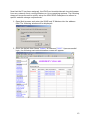
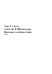
1. Open Web browser and enter the XDAS local IP Address into the address
field. The following window will be displayed:
2. Enter the default User Name “Admin” & Password “0000”. Upon successful
login, the following main administration screen will appear:
13
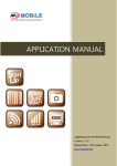
3. In order to create a new storage configuration, the existing Aberdeen preconfigured RAID and Volume sets must be deleted and re-created.
4. Delete existing RAID and Volume sets by clicking “Delete RAID Set”
5. Confirm the operation by checking the confirmation box then continue by
clicking “Submit”.
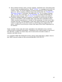
6. Create new RAID set by clicking “Create Raid Set”.
7. Select all available drives by checking each box next to each drive.
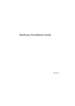
8. Select “Create Volume Set”. The following screen will appear:
14
9. Enter desired volume name, volume capacity, and Raid Level. Everything else
should remain at default setting. Check “Confirm” to complete the volume set
creation. Note: The XDAS supports volume sizes beyond 2TB for Windows
and Linux. When creating volumes larger than 2TB, select the “Greater Two
TB Volume Support” drop down list and select “No” for no support beyond
2TB, “64-LBA” for Linux/Unix, or “For Windows” to enable functionality for
Windows-based servers. Click “Confirm” to complete volume set creation.
10.Continue creating additional volumes if necessary by performing the same
steps outlined above until available disk space has been exhausted. Note:
Under normal circumstances, it should not be necessary to create more than
a single Raid Set. The advantage is that many Raid volumes can be created
under a single Raid 5 set which results in sacrificing just a single drive for
parity, instead of one drive per volume like many other Raid Subsystems on
the market.
Newly created volume sets will not be available to the attached server until the
volumes have completed initialization. Initialization time varies based on the size of
the Raid Set, number of volume sets, and of course the size and number of
member hard disk drives.
For complete XDAS Raid Subsystem setup options and parameters, please refer to
the XDAS manual located on the enclosed AberSAN i100/i300 CD
15
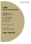
ABERDEEN XDAS SERIES
RAID SUBSYSTEM
HARDWARE INSTALLATION GUIDE
Ver. 1.0
.
16
XDAS Series RAID Subsystem
Hardware Installation Guide
Ver. 1.1
Hardware Installation Guide
Copyright ©2003
This guide and any accompanying software and firmware are copyrighted. No
parts of this publication may be reproduced, stored on a retrieval system, or
transmitted, in any form or by any means, electronic, mechanical, photocopy,
recording, or otherwise, without prior written consent except for copies retained
by the purchaser for backup purposes.
All rights Reserved- Printed in Taiwan.
Notice
We make no warranties with respect to this documentation either express or
implied and provide it "as it". This includes but is not limited to any implied
warranties of merchantability and fitness for a particular purpose. The
information in this document is subject to change without notice. We assume no
responsibility for any errors that may appear in this document.
The manufacturer shall not be liable for any damage, or for the loss of
information resulting from the performance or use of the information contained
herein
Trademarks
Product names used herein are for identification purposes only and may be the
trademarks of their respective companies. All trademarks or registered
trademarks are properties of their respective owners.
ii
Hardware Installation Guide
R
Reegguullaattoorryy iinnffoorrm
maattiioonn
For Europe
This drive is in conformity with the EMC directive.
Federal Communications Commission (FCC)
Statement
This equipment has been tested and found to comply with the limits for a Class
A digital device, pursuant to part 15 of the FCC Rules.
Those limits are designed to provide reasonable protection against harmful
interference in a residential installation. This equipment generates, uses and
can radiate radio frequency energy and, if not installed and used in accordance
with the instructions, may cause harmful interference to radio communications.
However, there is no guarantee that interference will not occur in a particular
installation. If this equipment does cause harmful interference to radio or
television reception, which can be determined by turning the equipment off and
on, the user is encouraged to try to correct the interference by one or more of
the following measures:
Reorient or relocate the receiving antennas.
Increase the separation between the equipment and receiver.
Connect the equipment into an outlet on a circlet different from that to which the
receiver is connected.
Consult the dealer or an experienced radio/TV technician for help.
Warning:
A shielded-type power cord is required in order to meet FCC emission limits and
also to prevent interference to the nearby radio and television reception. It is
essential that only the supplied power cord be used.
Use only shielded cables to connect I/O devices to this equipment.
You are cautioned that changes or modifications not expressly approved by the
party responsible for compliance could void your authority to operate the
equipment.
iii
Hardware Installation Guide
A
Abboouutt TThhiiss H
Haarrddw
waarree IInnssttaallllaattiioonn G
Guuiiddee
Welcome to Hardware Installation Guide. This guide is designed to be used as
step-by-step instructions for installation of your subsystem, and covers
everything you need to know in learning how to operation, troubleshooting and
future upgrades. For the detail about how to configure your subsystem, please
refer to the Software Operation manual.
S
Syym
mbboollss iinn TTeexxtt
These symbols may be found in the text of this guide. They have the following
meanings.
Caution
This icons indicates that failure to follow directions could result in personal
injury, damage to your equipment or loss of information.
Note
This icon presents commentary, sidelights, or interesting points of
information. .
Important terms, commands and programs are put in Boldface font.
Screen text is given in screen font.
iv
Hardware Installation Guide
Contents
ABOUT THIS HARDWARE INSTALLATION GUIDE .................................. IV
SYMBOLS IN TEXT ................................................................................ IV
CONTENTS ............................................................................................. V
CHAPTER 1. INTRODUCTION ............................................................. 1
MODEL VARIATIONS ............................................................................. 1
FEATURES ............................................................................................. 1
UNDERSTANDING THE XDAS RAID SUBSYSTEM ................................ 3
Front Panel Overview..................................................................... 3
Rear Panel Overview ...................................................................... 4
CHAPTER 2. INSTALLATION............................................................... 6
UNPACKING & CHECKING THE EQUIPMENT ........................................... 6
WHAT ELSE YOU NEED .......................................................................... 7
ESD PRECAUTION ................................................................................. 7
INSTALLING HARD DISKS ....................................................................... 7
INSTALL THE XDAS RAID SUBSYSTEM IN A RACK ............................ 9
SYSTEM CONNECTION ......................................................................... 10
CHAPTER 3. TROUBLE SHOOTING ................................................. 11
REPLACE THE CONTROLLER ................................................................ 11
REPLACING / UPGRADING DIMM....................................................... 12
Specifications:............................................................................... 12
Architecture of supported DIMM: ................................................ 12
Installing DIMM ........................................................................... 13
HOT SWAPPING TO REPLACE THE FAN MODULE.................................. 14
HOT SWAPPING TO REPLACE THE POWER MODULE ............................. 15
APPENDIX A .......................................................................................... 17
CONNECTORS .............................................................................. 17
APPENDIX B. SPECIFICATIONS ............................................ 20
SPECIFICATIONS .................................................................................. 20
v
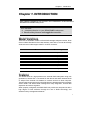
Chapter 1. Introduction
Chapter 1. INTRODUCTION
T
o the Aberdeen
Thhiiss cchhaapptteerr iinnttrroodduucceess tthhee ffeeaattuurreess aanndd ccaappaabbiilliittiieess oof
XDAS Series RAID subsystem.
YYoouu w
wiilll ffiinndd::
Ö
Ö A full introduction to your XDAS RAID subsystem.
Ö
Ö D
Deettaaiillss ooff kkeeyy ffeeaattuurreess aanndd ssuupppplliieedd aacccceessssoorriieess..
M
Mooddeell V
Vaarriiaattiioonnss
There are six available models in XDAS RAID storage subsystem series, three
of them utilize Ultra320 SCSI as Host interface, each with 8,12 or16 device bays.
Another three models support 2Gb FC via SFP connector.
Model Name
Host Interface
Device bays
AL-6080S
2 x Ultra320 SCSI
8 bays
AL-6080F
2 x 2Gbps FC
8 bays
AL-6120S
2 x Ultra320 SCSI
12 bays
AL-6120F
2 x 2Gbps FC
12 bays
AL-6160S
2 x Ultra320 SCSI
16 ays
AL-6160F
2 x 2Gbps FC
16 bays
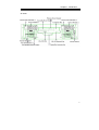
FFeeaattuurreess
The XDAS series is a high performance, external RAID subsystem using new
generation of Serial ATA 1.0 channels for disk drives and either Ultra320 SCSI
or 2Gbps Fibre channel I/O standard to connect services to Host computer.
Target usage ranges are set from small business to departmental and corporate
server needs. The XDAS RAID is designed for easy integration, smooth data
expansion and server migration.
When properly configured, the XDAS RAID can provide non-stop service with a
high degree of fault tolerance through the use of RAID technology and
advanced array management features.
1
Hardware Installation Guide
The XDAS series supports the following features:
z
High performance super scalar Intel Xscale 80321 IO processor.
z
Superior Array Management Firmware supports RAID levels 0, 1
(0+1), 3, 5, 6 and JBOD RAID configurations.
z
Advanced 100MHz/64-bit PCI-X bus architecture
z
Cache memory utilizes the Fastest 64-bit 200Mhz ECC DDR SDRAM
and cache memory size up to 1 gigabytes.
z
Dual Ultra-320 SCSI Host Interconnect supported Æ AL-6xx0S
z
Dual Loop of 2Gb/sec Fibre Channel via SFP connector Æ AL-6xx0F
z
New generation Serial ATA 1.0 Drive Interface supported,
AL-6160 Æ Up to 16 SATA drives via two 8 channels SATA interface.
AL-6120 Æ Up to 12 SATA drives via two 8 channels SATA interface.
AL-6080 ÆUp to 8 SATA drives via single 8 channels SATA interface.
2
z
Redundant and Hot Swappable Fan, Power and Drives.
z
Hot Swap, Hot Spare and Automatic Drive Rebuild Supported.
z
Configuration and environmental information is accessible either via
the control panel or Serial Port or 10/100 Ethernet LAN port.
z
E-mail event notification.
z
Load sharing hot swappable redundant power system with PFC
function.
z
Host System independent.
z
Operating System independent.
Chapter 1. Introduction
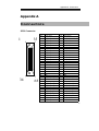
Understanding the XDAS RAID subsystem
Front Panel Overview
LCD Module
Driver Bay numbering convention
The enclosure bay numbering convention is shown in following figure. A bay is
designed to house a single 1.0-inch high, 3,5-inch hard disk drive in his carrier
module.
AL-6080
AL-6120
3
Hardware Installation Guide
AL-6160
Drive Bay
Rear Panel Overview
AL-6120 & AL-6080
4
Chapter 1. Introduction
AL-6160
5
Hardware Installation Guide
Chapter 2. INSTALLATION
This chapter presents:
Ö
Ö
Ö
Ö
Ö
Ö
Ö
Ö
IInnssttrruuccttiioonnss oonn uunnppaacckkiinngg &
meenntt
& cchheecckkiinngg tthhee eeqquuiippm
IInnssttrruuccttiioonnss oonn hhoow
w ttoo iinnssttaalll H
Haarrdd ddiisskk ddrriivvee
IInnssttrruuccttiioonnss oonn hhoow
t
o
i
n
s
t
a
l
l
RAAIID
D iinn aa R
Raacckk..
w to insta l XDAS R
IInnssttrruuccttiioonnss oonn hhoow
w ttoo ccoonnnneecctt XDAS RAID.
U
Unnppaacckkiinngg &
& cchheecckkiinngg tthhee E
Eqquuiippm
meenntt
Before unpacking the XDAS RAID subsystem, prepare a clean, stable surface
to put on the contents of XDAS RAID shipping container. Altogether, you should
find following items in the package :
XDAS SCSI to SATA Subsystem
z
XDAS RAID subsystem x1
z
CD-ROM x 1 ( Includes Hardware Installation
Guide, Software operation Manual & HTTP
Proxy Server utility for Web browser-based
Configuration).
z
Ultra320 SCSI Cable x1
z
Null cable x1
z
Ultra320 SCSI Active Terminator x1
z
Power Cord x 2
z
Spare Fan x 1
z
Spare Drive Bay x 1
z
Rails for Rack
z
Mounting screws (bag) ×1
XDAS Fibre to SATA Subsystem
z
XDAS RAID subsystem x1
z
CD-ROM x 1 ( Includes Hardware Installation
Guide, Software operation Manual & HTTP
Proxy Server utility for Web browser-based
6
Chapter 2. Installation
Configuration).
z
Null cable x1
z
Power Cord x 2
z
Spare Fan x 1
z
Spare Drive Bay x 1
z
Rails for Rack
z
Mounting screws (bag) ×1
Note
To avoid the unmatched connector type between the Fibre HBA in the Host
computer and XDAS RAID, XDAS RAID doesn’t include the Fibre cable with
the standard shipping.
W
Whhaatt eellssee yyoouu nneeeedd
z
Hard disk drives (different RAID levels requires different numbers of HDDs.
Refer to Software Operation manual for more detail information.
z
Host computer with SCSI or Fibre interface.
z
Dedicated terminal or PC with third party communication software that
supports ANSI terminal emulation (required for viewing Monitor Utility)
E
ES
SD
DP
Prreeccaauuttiioonn
Use a suitable anti-static wrist or ankle strap and observe all conventional ESD
precaution when handle XDAS RAID’s modules and components. Avoid contact
with backplane components and module connectors.
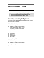
IInnssttaalllliinngg hhaarrdd ddiisskkss
The XDAS RAID series includes 8/12/16 ( depends on models) hot swappable
drive bays. The following sections describe how to install disks into XDAS RAID
subsystems.
Remove the empty hot swappable
driver bays
1. Push the unlock botton then slide
down the Releaser on drive bays .
2. Left the handle to disengage the
drive bay from the slot.
7
Hardware Installation Guide
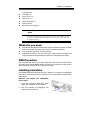
Loading Hard Disk to the drive bay.
1. Put HDD into the bay.
2. Fasten all 4 screws to mount HDD in
the bay and make sure the HDD is
properly tightened.
Place drive bays back into the system
1. Slide in drive bay, make sure the
handle is open fully.
2. Close the handle to engage the drive
bay into the slot.
Note
The hard drives in a RAID array should match in size and speed. All drives in
any array should be identical models with the same firmware versions. RAID
arrays can use any size drive, however the smallest drive will determine the
size of the array.
Caution
Only use the screws offered with XDAS RAID subsystem. Longer screws might
cause the drive damage.
Caution
All the drive bays ( with or without hard drive) must be placed in the XDAS
subsystem. XDAS's cooling system is designed with full of drive bays. Missing
drive bays might cause the subsystem damage.
8
Chapter 2. Installation
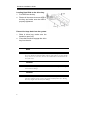
Intsall the RAID XDAS subsystem in a Rack
You are shipped one rackmounting kit for each XDAS RAID subsystem that you
intend to rackmount. XDAS RAID subsystem is designed for installation into a
industry-standard 19-inch rackmount cabinet. Following the use of this section
for installing the XDAS RAID subsystem into a Rack
Assemble the Slide Rails
1. Measure the depth of the rack enclosure,
then see the detail drawings as bellow to
assemble the Slide Rails.
Mount the slide rails in the rack.
1. Install the slide rails from the lowest
available position.
2. If necessary, use the mounting brackets
to accommodate the different types
of rack. See the detail drawing as bellow :
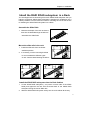
Install the XDAS RAID subsystem into the Rack Cabinet
1. Lift the XDAS RAID subsystem ( one person on each side of the XDAS
RAID) and approach the rack with the button-back of the XDAS RAID
subsystem facing the end of Slide rails.
2. Slide the XDAS RAID subsystem evenly into the rack cabinet all the way.
9
Hardware Installation Guide
3. Using the rackmount screws , secure the top and bottom of the XDAS RAID
subsystem to the rack frame.
Caution
The XDAS RAID subsystem is heavy, two person are required to move the system
in the procedure.
S
Syysstteem
mC
Coonnnneeccttiioonn
Connect all cables and power cord as shown below :
Cable
XDAS RAID
Device
Purpose
Null Cable
RS-232 Port
ANSI Terminal or a PC with Configuration Utility
Terminal emulator.
SCSI cable /
Primary SCSI/ FC-AL
HBA of Host computer
Fibre cable
Secondly SCSI/ FC-AL
Power Cord
Power inlet
A/C power outlet
A/C power input
RJ 45 Cable
Ethernet Port
Switch or HUB
Connect to Internet .
Host interface between
RAID and Host computer
Note
XDAS RAID subsystem do not require the installation of different drivers for
use with different operating systems. XDAS RAID is independent and
transparent to the host operating system.
10
Chapter 3. Trouble Shooting
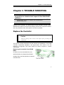
Chapter 3. TROUBLE SHOOTING
This chapter contains trouble shooting procedures and
suggestions to minimize their impact on the XDAS RAID
operation :
Ö Instructions on how to replace the components of the XDAS
R
RAAIID
D ssuubbssyysstteem
m..
If the fault LED on the front panel and LCD of XDAS RAID lights red and LCD
displays a error message , or if XDAS RAID’s Internet manager indicates a fault,
determine the reason for this alert immediately. Examine the component LEDs to
see if any indicates a fault, then replace it as soon as possible.
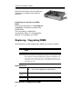
R
Reeppllaaccee tthhee C
Coonnttrroolllleerr
Caution
Read the replacing notices earlier in this chapter before proceeding with
replacement.
This section provides instructions for the removal and installation of the RAID
controller components indicated in the figure below. This section is for the
reference of engineers. End users should not need to replace or remove
components.
Removing the controller from XDAS
RAID :
In order to access controller box, turn
anti-clock wise to release three thumb
screws, then use the eject bar to remove
controller box.
11
Hardware Installation Guide
Disconnect all cables, then unscrew four
fasteners on controller and upward to
remove it.
Installing the controller into XDAS
RAID:
Reverse the procedure of “removing the
controller” to install the controller into
XDAS RAID.
Then according to “Appendix C.
Configuration table” on “Soft Operation
Manual” to reconfigure your RAID
R
Reeppllaacciinngg // U
Uppggrraaddiinngg D
DIIM
MM
M
XDAS RAID are normally supplied with 128MB cache memory installed.
Note
There's no set formula to determine how much cache memory to use,
but as a general rule, a workstation, with mostly very large files, such
as for audio or video editing and playback, graphics or CAD files, can
benefit from a large cache. File servers, with multiple random access of
varying file size, generally have little or no performance improvement
with additional cache.
Specifications:
Type
184-pin DDR DIMM module (DDR-266)
ECC, without Register and Unbuffered.
Parity
(ECC)
With parity for data security.
Size
From 64MB, 128MB, 256MB, 512MB to 1GB
Architecture of supported DIMM:
12
Chapter 3. Trouble Shooting
Size
Architecture
64 MB
9 (8M bit x 8)
128 MB
9 (16M bit x8)
256 MB
9 (32M bit x 8)
512 MB
9 (64M bit x 8)
1 GB
9 (128M bit x 8)
Installing DIMM
To install a DIMM, ensure the system power is off and disconnected. Then:
1. Turn anti- lock wise to release three thumb
screws, then use the eject bar to remove
controller box.
2. Remove the daughter board.
3. Insert a memory card at a 45-degree angle
into the memory card socket so that the
gold teeth of the card are no longer visible.
4. Press the card down firmly until the latches
lock it into place.
Before starting any kind of hardware installation, please ensure that all power
switches have been turned off and all power cords disconnected to prevent
personal injury and damage to the hardware
13
Hardware Installation Guide
Use screws provided with XDAS system only. Longer or shorter screws may
cause electric shorting or un-proper installed.
Static electricity can damage electronic components. To guard against such
damage:
Work in a static-free environment
Wear a grounded anti-static wrist strap
Store uninstalled components in anti-static bags
Handle PCBs by their edges and avoid touching chips and connectors.
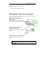
H
Hoott S
Sw
waappppiinngg ttoo rreeppllaaccee tthhee FFaann M
Moodduullee
This section provides instructions for the removal and installation of the Fan
Module indicated in the figure below.
Removing the Fan Module from XDAS :
Remove the Fan modules by slide the
release button left and pull the module out
of system.
Installing the Fan module into XDAS :
Insert a Fan module.
Replace the Fan in Fan module
1. There are two failure LEDs on the rear of
Fan module. Check which LED lights to
yellow.
2. Remove the Fan modules by anti-clock
wise to release the thumb screw then slide
it back and lifting off.
14
Chapter 3. Trouble Shooting
3. Release the screw to remove the defect
fan.
4. Insert the spare Fan and fasten the screw.
H
Moodduullee
Hoott S
Sw
waappppiinngg ttoo rreeppllaaccee tthhee P
Poow
weerr M
This section provides instructions for the removal and installation of the Power
Module indicated in the figure below.
Removing the Power Module from
XDAS AL-6160 :
Unscrew the fastener, then push right the
release button, slide it back and lifting off.
Removing the Power Module from
XDAS Al-6120 & AL-6080 :
Unscrew the fastener, then slide it back and
lifting off.
Installing the Power module into XDAS :
Insert a Power module then fasten the
screw.
15
Hardware Installation Guide
The Power indicator will turn bright “Green” to indicate it has powered on
16
Appendix A. Connectors
Appendix A
C o n n e ct o r s
SCSI Connector
1
34
35
68
Pin#
Signal Name
Pin#
Signal Name
1
SCSI_AC_DAT<12>+
35
SCSI_AC_DAT<12>-
2
SCSI_AC_DAT<13>+
36
SCSI_AC_DAT<13>-
3
SCSI_AC_DAT<14>+
37
SCSI_AC_DAT<14>-
4
SCSI_AC_DAT<15>+
38
SCSI_AC_DAT<15>-
5
SCSI_AC_PAR<1>+
39
SCSI_AC_PAR<1>-
6
SCSI_AC_DAT<0>+
40
SCSI_AC_DAT<0>-
7
SCSI_AC_DAT<1>+
41
SCSI_AC_DAT<1>-
8
SCSI_AC_DAT<2>+
42
SCSI_AC_DAT<2>-
9
SCSI_AC_DAT<3>+
43
SCSI_AC_DAT<3>-
10
SCSI_AC_DAT<4>+
44
SCSI_AC_DAT<4>-
11
SCSI_AC_DAT<5>+
45
SCSI_AC_DAT<5>-
12
SCSI_AC_DAT<6>+
46
SCSI_AC_DAT<6>-
13
SCSI_AC_DAT<7>+
47
SCSI_AC_DAT<7>-
14
SCSI_AC_PAR<0>+
48
SCSI_AC_PAR<0>-
15
GND
49
GND
16
GND
50
GND
17
TERMPWRA
51
TERMPWRA
18
TERMPWRA
52
TERMPWRA
19
GND
53
GND
20
GND
54
GND
21
SCSI_AC_ATN_L+
55
SCSI_AC_ATN_L-
22
GND
56
GND
23
SCSI_AC_BSY_L+
57
SCSI_AC_BSY_L-
24
SCSI_AC_ACK_L+
58
SCSI_AC_ACK_L-
25
SCSI_AC_RST_L+
59
SCSI_AC_RST_L-
26
SCSI_AC_MSG_L+
60
SCSI_AC_MSG_L-
27
SCSI_AC_SEL_L+
61
SCSI_AC_SEL_L-
28
SCSI_AC_CD_L+
62
SCSI_AC_CD_L-
29
SCSI_AC_REQ_L+
63
SCSI_AC_REQ_L-
30
SCSI_AC_IO_L+
64
SCSI_AC_IO_L-
31
SCSI_AC_DAT<0>+
65
SCSI_AC_DAT<0>-
32
SCSI_AC_DAT<9>+
66
SCSI_AC_DAT<9>-
17
Hardware Installation Guide
33
SCSI_AC_DAT<10>+
67
SCSI_AC_DAT<10>-
34
SCSI_AC_DAT<11>+
68
SCSI_AC_DAT<11>-
Ethernet RJ-45 Connector
Pin#
1.
8.
Signal Name
1
TX+
2
TX-
3
RX+
4
NC
5
NC
6
RX-
7
NC
8
NC
Fibre SFP
Pin#
Signal Name
1
3
VEFT
TFAULT
TDIS
4
MOD_DEF(2)
5
MOD_DEF(1)
6
MOD_DEF(0)
2
7
Rate Select
8
LOS
9
11
VEER
VEER
VEER
12
RD-
10
13
RD+
14
17
VEER
VCCR
VCCT
VEET
18
TD+
19
TD-
20
VEET
15
16
18
Appendix A. Connectors
RS-232 & Modem Male Connector
Pin#
1
2
3
4
5
Signal
DCD
RXD
TXD
DTR
GND
Pin#
6
7
8
9
Signal
DSR
RTS
CTS
TXC
19
Hardware Installation Guide
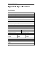
Appendix B. Specifications
Specifications
RAID Architecture
Intel Xscale 80321 I/O processor
Proprietary ASIC to support extreme performance RAID 6 function.
Up to 1GB 200MHz DDR SDRAM on one DIMM socket with ECC protection
Marvell 8 channels SATA controller (88SX5080)
RAID Features
RAID Levels : 0, 1, 3, 5, 0+1, 6 & JBOD
Multiple RAID selection
Online RAID level/stripe size migration
Online Array roaming
Online capacity expansion and RAID level migration simultaneously
Instant availability and background initialization
Automatic drive insertion / removal detection and rebuilding
Host Interface
AL-XXXXS
AL-XXXXF
Two Ultra320 SCSI Channels 320MB/sec per channel
Two 2Gbps Fibre Channels –
200MB/sec per channel
Drive Interface
AL-6080
AL-6120
AL-6160
8 SATA 1.0 channel
-1.5Gbps
12 SATA 1.0 channel
-1.5Gbps
16 SATA 1.0 channel
-1.5Gbps
Monitors/Indicators
LCD Control Panel for setup, alarm mute and configuration
System status indication through LCD, LED and alarm buzzer
All system events can be sent to multiple user alerts to be via ‘ Plain English’
e-mails.
RAID Management
20
Appendix B. Specification
Field-upgradeable firmware in flash ROM.
Firmware-embedded manager via RS-232 port.
Firmware-embedded SMTP manager – Monitor all system events and user can
select either single or multiple user alerts to be sent via ‘ Plain English’ e-mails.
Firmware-embedded Web Browser-based RAID manager via 10/100 Ethernet port
Operating System
OS independent and transparent.
Environmental /Physical
Cooling System
Hot swappable and redundant Cooling Fan modules.
Power System
AL6080 & AL 6120
AL-6160
Redundant by Dual 350W
Redundant by Dual 460W
Power modules with PFC
Power modules with PFC
feature, Load Sharing type
feature, Load Sharing type
and cableless design.
and cableless design.
AC Voltage 110-230 VAC
Ac Frequency 50-60Hz
Operating Temperature : 10 to 35 degree C.
Electrical
Temperature
Relative Humidity 20% to 80% non-condensing
Dimensions
Weight
AL-6080 & 6120 446mm(W) x 480mm(D) x 88.8mm (H)
AL-6160
446mm(W) x 470mm(D) x 133mm (H)
AL-6080
13.5Kg(W/O HDD)
AL-6120
13Kg (W/O HDD)
AL-6160
18Kg (W/O HDD)
Specifications subject to change without notice.
21