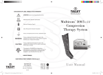
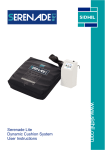
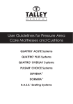
1
USER MANUAL DYNA-FORM™ Low Air Loss System Issued By: Direct Healthcare Services Ltd. Document No: UM-Q5LAL-2013 Version: 01 Date: 2013.03.01 TABLE OF CONTENTS ............................................................................................................................................................ PAGE TABLE OF CONTENTS ............................................................................................................................. 2 STATEMENTS & SYMBOLS ..................................................................................................................... 3 Note, Caution, Warning & Danger statements .................................................................................... 3 Symbols: .............................................................................................................................................. 3 INTRODUCTION ....................................................................................................................................... 4 General ................................................................................................................................................ 4 Intended Use ....................................................................................................................................... 4 Contraindication ................................................................................................................................... 4 PACKAGE CONTENT ............................................................................................................................... 5 Pump ................................................................................................................................................... 5 Mattress ............................................................................................................................................... 5 Cover Sheet ......................................................................................................................................... 5 Manual ................................................................................................................................................. 5 PRODUCT FUNCTIONS ........................................................................................................................... 6 Pump ................................................................................................................................................... 6 Mattress ............................................................................................................................................... 6 INSTALLATION .......................................................................................................................................... 7 EARTHING INSTRUCTIONS .................................................................................................................... 8 OPERATION .............................................................................................................................................. 9 General ................................................................................................................................................ 9 OPERATION (continued) ......................................................................................................................... 10 CPR function ..................................................................................................................................... 10 CLEANING ............................................................................................................................................... 11 Pump .................................................................................................................................................. 11 Mattress .............................................................................................................................................. 11 HANDLING & STORAGE ........................................................................................................................ 12 MAINTENANCE ....................................................................................................................................... 13 General .............................................................................................................................................. 13 Low pressure ..................................................................................................................................... 13 TROUBLESHOOTING............................................................................................................................. 14 SPECIFICATIONS ................................................................................................................................... 15 MANUFACTURER INFORMATION ......................................................................................................... 16 2 STATEMENTS & SYMBOLS Note, Caution, Warning & Danger statements NOTE!! Tips or information users should be aware of. CAUTION: Correct operating or maintenance procedures to be carefully followed to prevent damage to or destruction of the equipment or other properties. WARNING/DANGER: Attention has to be paid to a potential danger that requires correct procedures or practices in order to prevent personal injury. Symbols: Symbols on the printed label on the outside package box are as below: Earthing Terminal Type BF Equipment Always read the operating instructions before use. 3 INTRODUCTION This manual should be used for the initial set up of the system and for reference purposes. General Our Low Air Loss system is a high quality and affordable air support surface suitable for very high-risk pressure ulcer prevention and treatment. It has been specifically designed for prevention and treatment of existing pressure ulcers and offers an optimal solution for pressure redistribution. The system has been tested and certified for the following standards: UL 60601-1 CAN/CSA C22.2 No. 601.1 IEC 60601-1 IEC 60601-1-2 IEC 60601-1-11 Intended Use The system is designed and constructed to reduce the incidence of pressure ulcers while optimising patient comfort. It is also indicated for: Individual home care and long-term hospital care settings Pain management as prescribed by a physician Contraindication Patient conditions for which the application of pressure redistributing therapy on an alternation system is contraindicated are as follows: Cervical or skeletal traction Unstable spinal cord injuries 4 PACKAGE CONTENT Check inside the package for the following contents. Should any of the following items be missing or damaged, please contact your local dealer or service center for replacement immediately. Pump Make sure you received the correct pump model. Each pump model works with specific Mattress models. Mattress The Low Air Loss (LAL) mattress supplied with the pump is an 8” nylon/pu cell-type construction and includes a foam base inserted into a pocket under the air cells. For mattresses with cells bigger than 8” in height, the foam base can be omitted. Manual Please read this manual completely before using this product! 5 PRODUCT FUNCTIONS Pump The functions of the LAL pump are described as below. 8 6 7 4 5 (1) POWER switch (2) MUTE switch (yellow) (3) SEAT switch (yellow) (4) AUTOFIRM switch (yellow) 2 3 (5) LOCK switch (green) (6) POWER FAILURE indicator (red) (7) LOW PRESSURE indicator (red) 1 (8) PRESSURE SELECTION Keys (green) POWER switch (1) The POWER switch is at the lower right side of the pump. Turning the power switch ON/OFF will start/stop the pump. The switch lights up when the power is ON, and extinguishes when the power is OFF. MUTE switch (2) The audible/visible alarm turns on either when the pressure is low or the system fails. Press the Mute switch to mute the audible alarm, and the MUTE indicator (yellow) will light up. The alarm indicator will continue flickering. Re-press the Mute switch to re-activate the audible alarm and to extinguish the MUTE indicator. SEAT switch (3) Press the SEAT switch to increase the pressure in each cell by 5mmHg. The SEAT indicator (yellow) lights up when the system is in SEAT mode. To cancel SEAT mode, press the SEAT switch. AUTOFIRM switch (4) Press the AUTOFIRM switch to set AUTOFIRM mode to quickly inflate the air mattress to the maximum pressure which facilitates nursing care and bed mobility. The AUTOFIRM indicator (yellow) lights up when the system is in AUTOFIRM mode. The system will automatically return to the previous mode 30 minutes after the AUTOFIRM mode is in operation. It is also possible to cancel AUTOFIRM mode by pressing the Pressure Selection keys or Seat switch. LOCK switch (5) Press and hold the LOCK switch for 2 seconds to lock the panel. Press and hold the LOCK switch for 2 seconds again to unlock the panel. The LOCK indicator (green) lights up when the panel is locked. The panel will automatically enter locked mode if no control panel operations are entered for over 30 seconds. POWER FAILURE indicator (6) This indicator (red) flickers when there is no power input to pump. LOW PRESSURE indicator (7) This indicator (red) flickers when the pressure is below the pre-defined level. PRESSURE SELECTION Keys (8) The PRESSURE SELECTION Keys can be used to determine internal cell pressure in the mattress. Eight pressure levels are indicated by the number of indicators (green) that light up as the pressure is increased to support your patient. Mattress The LAL system comes with an 8” Nylon/PU air-cell construction complete with 2” foam base encased in a wipe clean welded cover as standard. Various models of cell-type mattresses of different materials (Nylon/PU or PU) and constructions are available. Please consult with your dealer for more information regarding alternative mattress specifications. 6 INSTALLATION Step 1 > Place the mattress flat on the bed frame. The inflation tubing should be towards the foot of the bed so that it can be connected to the inflation nozzles on the pump. See figure below for reference. Step 2 > Hang the pump over the frame or at the footboard of the bed. Make sure the pump is secured to the footboard. Step 3 > Securely connect the inflation tubes from the mattress to the pump’s inflating nozzles. Make sure they are properly attached! NOTE!! Make certain the air hoses are not kinked or tucked under the mattress. Also check if the CPR valve is properly attached. In line with MDA/2013/073 the manufacturer warns against the dangers of smoking in bed Step 4 > Plug the power cord into an electrical socket. NOTE!! This product is earthed. The power cord has an earth wire connected in the plug. This three-wire plug must be plugged properly into an electrical socket. Step 5 > Turn on the power by pressing the power switch at the right side of the pump. Proceed to the OPERATION section. Step 6 > Be sure to unplug the power cord when the pump is not in use. 7 EARTHING INSTRUCTIONS This product should be earthed. In the event of a short circuit, earthing reduces the risk of electric shock by providing an escape wire for the electric current. This product is equipped with a cord that contains an earthing wire inside the plug. DANGER - Improper use of the earthed plug can result in the risk of electrical shock. NOTE!! The earth wire is the green wire (with or without yellow stripe). Consult a qualified electrician or serviceman if the earthing instructions are not completely understood, or if in doubt as to whether the product is properly earthed. The plug will have 3 pins as shown in the plug below (figure A). If it is necessary to use an extension cord, use only a 3-pin extension cord that will accept the plug on the product. 8 OPERATION Always read the operating instructions before use! General This product is designed to provide maximum comfort to home care and long term hospital care patients. Be sure to use this product in a proper way to optimize its value. Here we provide some general information the user should be aware of. Regarding products: DO NOT use another pump with the supplied mattress. It is dangerous to use a pump with pressure capacity over 120 mmHg. This may result in cell-puncture. DO NOT change any component by yourself. Replacement or repair should always be completed by a suitably qualified person – please contact your local dealer or service centre for repair. For patients: The SEAT mode prevents the patient from bottoming out when the patient is in a sitting position. See the figure BELOW. HAND CHECK: Slide one hand between the patient’s sacral region and the air mattress to feel whether the pressure is properly adjusted. The optimal clearance range is 25 to 40 mm (1” to 1½”). NOTE!! The hand check procedure is an internationally recommended procedure devised by the Agency for Health Care Policy and Research. Turn the power ON A BEEP sound will begin the operation. The indicator (green) of the power switch will light up, and the pump starts to pump air into the mattress. The LOW PRESSURE indicator (red) will flicker as the inflation of the mattress takes place. NOTE!! The audible alarm is automatically muted on initial power-up and will not be heard when inflating the mattress for the first time. NOTE!! If the pressure does not reach 25 mmHg for 40 minutes after the pump is turned on, the audible alarm will start to beep, and the LOW PRESSURE indicator will continue flickering. Pressure adjustment The pressure of the mattress can be set by pressing the PRESSURE SELECTION keys. There are a total of 8 different pressure levels to selection. NOTE!! Pressing the [+] key will bring the pressure one level higher, and the [-] key will bring the pressure one level lower. It is recommended to follow the HAND CHECK procedure as demonstrated on page 9 to determine the appropriate pressure level. Automatic pressure control During normal operation, the pump will continually monitor pressure changes keeping them constant at the set level. If the pressure drops below the set pressure level, the blower will automatically speed up the inflation of the mattress. When the set pressure level is reached, the pump will stay at the specified rotation speed. 9 OPERATION (CONTINUED) NOTE!! If the pressure is consistently low, the audible alarm will beep and its indicator will light up to attract attention. If there is obvious leakage, for example caused by loose connection of tubes, the audible/visible alarm will be activated. For nursing care and bed mobility Press the AUTOFIRM switch to automatically inflate the mattress to the maximum level (above 45 mmHg) for about 30 minutes. The pump will return to the previous pressure level 30 minutes later. Placing the patient in the seating position Press the SEAT switch to for the even support and 5 mmHg higher pressure to prevent the patient from bottoming out when placing the patient in the seating position for feeding or other applications. To silence the alarm When the pressure drops below the pre-defined level, the LOW PRESSURE indicator will light up accompanied by a BEEPING alarm tone. If the pump loses power input, the POWER FAILURE indicator will light up accompanied by a BEEPING alarm tone. In any case, pressing MUTE switch will silence the alarm, but the indicator will continue flickering. Re-pressing the MUTE switch will re-activate the audible alarm. CPR function When there is an emergency to perform CPR on the patient, pull the CPR strap to release the air immediately from the mattress. The CPR strap is located at the front right-hand side of the mattress. Additionally, the air tubing set can also be removed from the pump unit. 10 CLEANING In this section, we describe the procedures to clean and decontaminate the pump. It is important to follow these procedures before using the system on patients. Cleaning of the system is required regularly between patients to prevent cross infection. The cover may be removed and will withstand thermal disinfection washing procedures described in the Department of Health Service Guidelines HSG(95)18. Pump DO NOT immerse or soak the pump. Check for external damage and move the pump to the cleaning area. Place the pump on a work surface and spray or wipe the outside of the case with a prepared sodium hypochlorite solution 1000 ppm. DO NOT spray any cleaning solution directly on the surface of the pump. DO NOT use Phenol based cleaning solutions as this may cause damage to the case. Wipe the pump case making sure all areas are clean (top and bottom, both sides) and not forgetting the mains cable. Wipe the faceplate. DO NOT allow excess cleaning solution on to the faceplate or control panel. (If solution gets inside, damage will occur.) Allow surface to thoroughly dry after cleaning. After the pump is thoroughly cleaned and dried, proceed to plug in the pump and test to see if it runs normally. Unplug the pump and store in a sealed polythene bag with a suitable identification tag. Mattress For daily cleaning wipe down all surfaces of the cover sheet with soap and water. DO NOT use solvents or alcohol-based cleansers e.g. Phenicol, Hibiscrub, Clearsol, Stericol or Hycoline as these will destroy the mattress materials. DO NOT autoclave. For thorough decontamination the mattress should be carefully cleaned with 1000ppm prepared solution of sodium hypochlorite rinsed and allowed to dry completely. Unzip the top cover from the mattress. Unzip the separate pocket and remove the foam underlay examining it for any staining. The outer cover can be machine washed at temperatures not exceeding 75°C and tumble dried on a cool setting. The air cells are unsnapped from one side and are carefully cleaned with 1000ppm prepared solution of sodium hypochlorite and allowed to dry. (Make sure to disconnect all the air cells, one by one, and spray the cleaning solution on all sides, including all the connecting tubes and hoses). Re-assemble the mattress and lay the mattress out flat; roll from the foot end towards the head end. Store in a sealed polythene bag with a suitable identification tag. 11 HANDLING & STORAGE When handling the mattress and preparing it for storage, please follow the brief guidelines below: Lay the mattress out flat and disconnect from the pump unit. Roll from the foot end towards the head end and once all the air has been expelled place the pump unit on top the mattress. Tightly roll the mattress and secure using the foot-end strap stretched around the rolled mattress to prevent unrolling. Do not fold, crease or stack the mattress. Place in a suitable carry bag. 12 MAINTENANCE General Regularly check the power cord and plug to see if there are abrasions or excessive wear – replace as necessary. Check the mattress cover for signs of wear or damage. Make sure the mattress cover and tubes are connected together correctly. Plug in the pump and check the airflow from the hose connection port. Check the air hoses to see if there are kinks or breaks. For replacement, please contact your local agent or dealer. Make sure the mattress tubing is securely connected to the pump. Check the pump and make sure both power and power indicator are off when the switch is turned off. Regularly check the external pump filter and clean/replace as necessary. Low pressure Examine if there is air leakage between the pump and the mattress connections or from the air mattress tubes. Check connectors between the air mattress and pump. If disconnected then reconnect. Check the CPR Valves. Be sure the outlets are sealed. Check each air-cell for potential leakage. Set the highest pressure level. Keep the tubes fully inflated and inspect for air leakage – please note that the tiny holes found on the surface of each air-cell are purposely positioned and any checks to the air cell are around the welded seams and T-connector. If there is any air leakage from the air-cells, contact your local agent or dealer to arrange replacement. 13 TROUBLESHOOTING Problems Solutions No Power to the Pump 1. Check if the plug is inserted firmly into the mains socket. 2. Turn on the power switch again. If the power indicator is ON and the pump doesn’t work, contact your local dealer immediately. If the power indicator is OFF, there may be a faulty socket. Try to connect the power cord to another socket. If the power indicator is still OFF, contact a qualified electrician for mains power check. Incomplete inflation 1. For a quick check, adjust the pressure to Firm. (LOW PRESSURE) 2. Check to see if the tubes connected to the pump are twisted or there is any leakage occurring. Always keep the tubes straight. Change tubes if there is any damage or kinking. Ensure the CPR valves are closed. Check each air-cell to ensure there is no damage. Slow air flow A dirty filter may decrease the air flow. Wash the filter with mild detergent to keep it clean. Check the air filter at the back of the pump at least once a month. 14 SPECIFICATIONS Item Classification Specifications Class I; IP21; AP/APG NO; Type BF Mattress type: Applied Part 20cm Nylon/PU type air-cells over CMHR foam (15cm + 5cm), with 4 × 0.8mm low air loss holes/per cell. Input Rating AC 230V 50Hz ; 12W Fuse Rating T2.5A, 250V Pressure Range 10 ~ 25 mmHg Pump Dimensions 270 x 170 x 310 mm (10¾” x 6¾” x 12¼”) Mattress Dimensions 2000 x 915 x 200mm Weight (Pump) (inc foam) 4.8 kg Temperature: Environment Requirements Operation: 10~35°C Storage: -15~50°C Shipping: -15~70°C Humidity: Operation: 20%~80% non-condensing Storage: 10%~90% non-condensing Safety Standards UL, c-UL (With respect to electric shock, fire and mechanical hazards only) CE EMC standards CISPR 11 Class B IEC 61000-3-2; IEC 61000-3-3; IEC 61000-4-2 IEC 61000-4-3; IEC 61000-4-4; IEC 61000-4-5 IEC 61000-4-6; IEC 61000-4-8; IEC 61000-4-11 Due to continual development of the above products, specifications are subject to change without prior notice. 15 MANUFACTURER INFORMATION NOTE!! The aforementioned specifications are also applicable to those areas operating with the same power supply range. AP/APG NO indicates the device is NOT suitable for use in the presence of flammable anesthetic mixture with air or with oxygen or nitrous oxide. Type BF symbol indicates the degree of protection against electric shock. Instructions or reference information for repair of equipment parts are provided by the manufacturer, please contact your local dealer for further information. Direct Healthcare Services Unit 8-10 Withey Court Western Industrial Estate Caerphilly CF83 1BF TEL: + 44 (0)845 459 9831 FAX: + 44 (0)845 459 9832 WEB: www.directhealthcareservices.co.uk Email: [email protected] 16