1
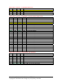
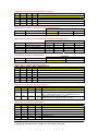
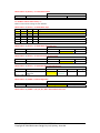
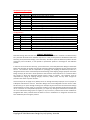
MD‐QUAD 2/3 FIRMARE VERSION 1.4 SETTINGS Please note: MD‐QUAD 2 hardware has serial numbers starting with MQA or MQB. MD‐QUAD 3 hardware has serial numbers starting with MQC. The latest USB Control Software and Specifications for this product can be downloaded at: www.decimator.com In Quad Split mode, input 1 is displayed in the top left quadrant, 2 in the Top Right, 3 in the bottom left and 4 in the bottom right. Use the rotary to select the menu and press the button to toggle the setting. When the settings are changed the Power LED will change to Red and change back to Green when they are saved. Defaults are highlighted. For all Menu Subsets when Rotary = 0. Input Status (Button is disabled) LED Status
LED Description Off
Green
Red Orange
1 Input 1 Format Detect
None
SD
HD 3G 2 Input 2 Format Detect
None
SD
HD 3G 3 Input 3 Format Detect
None
SD
HD 3G 4 Input 4 Format Detect
None
SD
HD 3G For all Menu Subsets when Rotary = 1. Menu Subset LED 1 LED 2 LED 3 LED 4 Menu Subset
Off Off Off
Off 0 Off Off Off
Green 1 Menu Subset = 0 / Rotary = 2. HDMI Output Type LED 1 LED 2 LED 3 LED 4 Output
Off Off Off
Off DVI RGB 4:4:4, No audio is passed
Off Off Off
Green HDMI RGB 4:4:4, 2 Audio channels passed
Off Off Green Off HDMI YCbCr 4:4:4, 2 Audio channels passed
Off Off Green Green HDMI YCbCr 4:2:2, 2 Audio channels passed
Off Green Off
Off HDMI RGB 4:4:4, 8 Audio channels passed
Off Green Off
Green HDMI YCbCr 4:4:4, 8 Audio channels passed
Off Green Green Off HDMI YCbCr 4:2:2, 8 Audio channels passed
Menu Subset = 0 / Rotary = 3. Output Select LED 1 LED 2 LED 3 LED 4 Output
Green Green Green Green Quad‐Split (GPI will override)
Green Off Off
Off Video Source 1
Off Green Off
Off Video Source 2
Off Off Green Off Video Source 3
Off Off Off
Green Video Source 4
MD‐QUAD 2/3 FIRMWARE VERSION 1.4 SETTINGS Copyright © 2012 Decimator Design Pty Ltd, Sydney, Australia 1
Menu Subset = 0 / Rotary = 4. Quad‐Split Audio Source LED 1 LED 2 LED 3 LED 4 Output
Green Off Off
Off Video Source 1
Off Green Off
Off Video Source 2
Off Off Green Off Video Source 3
Off Off Off
Green Video Source 4
Menu Subset = 0 / Rotary = 5. Quad‐Split / Test‐Pattern Mode Output Format LED 1 LED 2 LED 3 LED 4 Quad‐Split Output Format
Off Off Off Off 1. SD 720x487i59.94
Off Off Off Green 2. SD 720x576i50
Off Off Green Off 3. HD 1920x1080i60
Off Off Green Green 4. HD 1920x1080i59.94
Off Green Off Off 5. HD 1920x1080i50
Off Green Off Green 6. HD 1920x1080psf30
Off Green Green Off 7. HD 1920x1080psf29.97
Off Green Green Green 8. HD 1920x1080psf25
Green Off Off Off 9. HD 1920x1080psf24
Green Off Off Green 10. HD 1920x1080psf23.98
Green Off Green Off 11. HD 1920x1080p30
Green Off Green Green 12. HD 1920x1080p29.97
Green Green Off Off 13. HD 1920x1080p25
Green Green Off Green 14. HD 1920x1080p24
Green Green Green Off 15. HD 1920x1080p23.98
Green Green Green Green 16. HD 1280x720p60
Off Off Off Red 17. HD 1280x720p59.94
Off Off Red Off 18. HD 1280x720p50
Off Off Red Red 19. HD 1280x720p30
Off Red Off Off 20. HD 1280x720p29.97
Off Red Off Red 21. HD 1280x720p25
Off Red Red Off 22. HD 1280x720p24
Off Red Red Red 23. HD 1280x720p23.98
Red Off Off Off 24. 3G 1920x1080p60
Red Off Off Red 25. 3G 1920x1080p59.94
Red Off Red Off 26. 3G 1920x1080p50
Menu Subset = 0 / Rotary =6. Output Aspect, Size and Border LED 1 LED 2 LED 3 LED 4 Description
Off Off Off
Off 16:9 at 100% of Screen Size with No Border
Off Off Off
Green 16:9 at 100% of Screen Size with Border
Off Off Green Off 16:9 at 90% of Screen Size with No Border
Off Off Green Green 16:9 at 90% of Screen Size with Border
Off Green Off
Off 4:3 at 100% of Screen Size with No Border
Off Green Off
Green 4:3 at 100% of Screen Size with Border
Off Green Green Off 4:3 at 90% of Screen Size with No Border
Off Green Green Green 4:3 at 90% of Screen Size with Border
MD‐QUAD 2/3 FIRMWARE VERSION 1.4 SETTINGS Copyright © 2012 Decimator Design Pty Ltd, Sydney, Australia 2
Menu Subset = 0 / Rotary = 7. Select Input/s to Configure LED 1 LED 2 LED 3 LED 4 Selected Input to configure
Off Off Off
Off All inputs
Green Off Off
Off Video Source 1
Off Green Off
Off Video Source 2
Off Off Green Off Video Source 3
Off Off Off
Green Video Source 4
Menu Subset = 0 / Rotary = 8. Aspect format for Selected Input/s LED Status
LED Description Off
Green
Red 1 SD Output Aspect Ratio
Input = Output
Letter/Pillar box Centre Cut
LED 2, 3 and 4 are off. Menu Subset = 0 / Rotary = 9. Audio Meter Group Enable for Selected Input/s LED Status
LED Description Off
Green
Red Orange
1 Input 1 Group Enable None
1
2 1 & 2 2 Input 2 Group Enable None
1
2 1 & 2 3 Input 3 Group Enable None
1
2 1 & 2 4 Input 4 Group Enable None
1
2 1 & 2 Menu Subset = 0 / Rotary = A. UMD Enable LED Status
LED Description Off
Green 1 UMD Enable Off
On Menu Subset = 0 / Rotary = B. Audio Bar Scale LED 1 LED 2 LED 3 LED 4 Reference Level
Off Off Off
Off AES/EBU
Off Off Off
Green VU Off Off Green Off Extended VU
Off Off Green Green BBC (IEC 2a)
Off Green Off
Off EBU (IEC 2b)
Off Green Off
Green DIN (IEC 2b)
Off Green Green Off NORDIC (IEC 2b)
Menu Subset = 0 / Rotary = C. Audio Test Signals LED 1 LED 2 LED 3 LED 4 Audio Test Signals
Off Off Off Off Off
Off
Off
Off Green 1kHz on Group1, Pair 1 only
Off
Off
Green Off Pair 1 = 1kHz Tone, Pair 2 = 500Hz Tone
Pair 3 = 1kHz Broken Tone, Pair 4 = 500Hz Broken Tone Off
Off
Green Green 1kHz Tone on Left for Pair 1, 2, 3 & 4
1kHz Broken Tone on Right for Pair 1, 2, 3 & 4 Menu Subset = 0 / Rotary = D. Test Pattern LED 1 LED 2 LED 3 LED 4 Test Pattern
Off Off Off Off SMPTE HD Bars
Off
Off
Off Green Bars 100/0/100/0
Off
Off
Off Red Bars 100/0/75/0
Off
Off
Off Orange Bars 75/0/75/0
Off
Off
Green
Off Bars 100% & Red
Off
Off
Green
Green SMPTE EG 1 Bars
Off
Off
Green
Red Path Equalizer & PLL
MD‐QUAD 2/3 FIRMWARE VERSION 1.4 SETTINGS Copyright © 2012 Decimator Design Pty Ltd, Sydney, Australia 3
Menu Subset = 0 / Rotary = C. Test Pattern (Continued) LED 1 LED 2 LED 3 LED 4 Test Pattern
Off
Off
Green Orange Square on 4:3 Mon.
Off
Off
Red
Off Square on 16:9 Mon.
Off
Off
Red
Green 5 Step Y Staircase
Off
Off
Red
Red 5 Step UV Staircase
Off
Off
Red
Orange Y Sweep
Off
Green
Off
Off UV Sweep
Off
Green
Off
Green Y Multiburst
Off
Green
Off
Red UV Multiburst
Off
Green
Off
Orange Y Ramp
Off
Orange
Red
Off UV Moving In C ZP
Off
Orange
Red
Green UV Moving Out C ZP
Off
Green
Green
Off UV Ramp
Off
Green
Green
Green Pluge
Off
Green
Green
Red Convergence
Off
Green
Green Orange Tartan Bars
Off
Green
Red
Off 1 Field in 8 White
Off
Green
Red
Green White 100%
Off
Green
Red
Red White 75%
Off
Green
Red
Orange Black
Off
Green Orange
Off Red
Off
Green Orange Green Yellow
Off
Green Orange
Red Green
Off
Green Orange Orange Blue
Off
Red
Off
Off Magenta
Off
Red
Off
Green Cyan
Off
Red
Off
Red Y Static X ZP/L
Off
Red
Off
Orange Y Static X ZP/H
Off
Red
Green
Off Y Static Y ZP
Off
Red
Green
Green Y Moving Left X ZP
Off
Red
Green
Red Y Moving Right X ZP
Off
Red
Green Orange Y Moving Up Y ZP
Off
Red
Red
Off Y Moving Down Y ZP
Off
Red
Red
Green Y Moving Up XY ZP
Off
Red
Red
Red Y Moving Down XY ZP
Off
Red
Red
Orange Y Static C ZP
Off
Red
Orange
Off Y Moving In C ZP
Off
Red
Orange Green Y Moving Out C ZP
Off
Red
Orange
Red UV Static X ZP/L
Off
Red
Orange Orange UV Static X ZP/H
Off
Orange
Off
Off UV Static Y ZP
Off
Orange
Off
Green UV Moving Left X ZP
Off
Orange
Off
Red UV Moving Right X ZP
Off
Orange
Off
Orange UV Moving Up Y ZP
Off
Orange Green
Off UV Moving Down Y ZP
Off
Orange Green
Green UV Moving Up XY ZP
Off
Orange Green
Red UV Moving Down XY ZP
Off
Orange Green Orange UV Static C ZP
Off
Orange
Red
Off UV Moving In C ZP
Off
Orange
Red
Green UV Moving Out C ZP
MD‐QUAD 2/3 FIRMWARE VERSION 1.4 SETTINGS Copyright © 2012 Decimator Design Pty Ltd, Sydney, Australia 4
Menu Subset = 0 / Rotary = F. Test Pattern Enable LED Status
LED Description Off
Green 1 Test Pattern Off
On For all Menu Subsets when Rotary = E. Button 1 will reset all settings to their defaults. Menu Subset = 1 / Rotary = 2. Audio Meter Style LED 1 LED 2 LED 3 LED 4 Style
Off Off Green Green Vertical Bar and Float
Off Off Off
Green Vertical Bar
Off Off Green Off Vertical Float
Off Off Red
Red Horizontal Bar and Float
Off Off Off
Red Horizontal Bar
Off Off Red
Off Horizontal Float
Menu Subset = 1 / Rotary = 3. Audio Meter Reference Level LED Status
LED Description Off
Green
Red 1 Reference Level ‐20dBFS
‐18dBFS
‐15dBFS
Menu Subset = 1 / Rotary = 4. On Screen Input Format Enable LED Status
LED Description Off
Green
Red 1 On Screen Format Off
On for 5 seconds Always on
Menu Subset = 1 / Rotary = 5. Quad‐Split Mode Output Reference LED Status
LED Description Off
Green
Red Orange
1 Quad‐Split Mode Output Free‐run
Video Reference Source 1 LED 2, 3 and 4 are off. Menu Subset = 1 / MENU = 6. GPI Configuration LED Status
LED Description Off
Green 1 GPI Configuration 1
Configuration 2 Menu Subset = 1 / MENU = 7, 8, 9, A, B, C, D & F. Reserved for future use MD‐QUAD 2/3 FIRMWARE VERSION 1.4 SETTINGS Copyright © 2012 Decimator Design Pty Ltd, Sydney, Australia 5
GPI (General Purpose Inputs) Configuration 1 (Tallies) PIN NAME DESCRIPTION
1 Q1_TALLY_EN Ground pin to enable Tally on input 1
2 Q2_TALLY_EN Ground pin to enable Tally on input 2
3 Q3_TALLY_EN Ground pin to enable Tally on input 3
4 RX+ RS422/RS485 Positive Receive Pin
5 RX‐ RS422/RS485 Negative Receive Pin
6 Q4_TALLY_EN Ground pin to enable Tally on input 4
7 OS_TOGGLE Ground pin to toggle outputs between quad‐split and input 1, 2, 3 and 4.
8 GROUND
Use as reference ground.
Configuration 2 PIN NAME DESCRIPTION
1 Q1_PT_EN
Ground pin to enable pass‐through of input 1 to outputs. 2 Q2_PT_EN
Ground pin to enable pass‐through of input 2 to outputs. 3 Q3_PT_EN
Ground pin to enable pass‐through of input 3 to outputs. 4 RX+ RS422/RS485 Positive Receive Pin
5 RX‐ RS422/RS485 Negative Receive Pin
6 Q4_PT_EN
Ground pin to enable pass‐through of input 4 to outputs. 7 QS_EN Ground pin to enable Quad‐Split on outputs.
8 GROUND
Use as reference ground.
SERVICE WARRANTY Decimator Design warrants that this product will be free from defects in materials and workmanship for a period of 36 months from the date of purchase. If this product proves to be defective within this warranty period, Decimator Design, at its discretion, will either repair the defective product without charge for parts and labour, or will provide a replacement product in exchange for the defective product. In order to service under this warranty, you the Customer, must notify Decimator Design of the defect before the expiration of the warranty period and make suitable arrangements for the performance of service. The Customer shall be responsible for packaging and shipping the defective product to a designated service centre nominated by Decimator Design, with shipping charges prepaid. Decimator Design shall pay for the return of the product to the Customer if the shipment is to a location within the country in which the Decimator Design service centre is located. The Customer shall be responsible for paying all shipping charges, insurance, duties, taxes, and any other charges for products returned to any other location. This warranty shall not apply to any defect, failure or damage caused by improper use or improper or inadequate maintenance and care. Decimator Design shall not be obligated to furnish service under this warranty a) to repair damage resulting from attempts by personnel other than Decimator Design representatives to install, repair or service the product, b) to repair damage resulting from improper use or connection to incompatible equipment, c) to repair any damage or malfunction caused by the use of non‐Decimator Design parts or supplies, or d) to service a product that has been modified or integrated with other products when the effect of such a modification or integration increases the time of difficulty of servicing the product. MD‐QUAD 2/3 FIRMWARE VERSION 1.4 SETTINGS Copyright © 2012 Decimator Design Pty Ltd, Sydney, Australia 6