1
ADPRO VideoWall
by Xtralis
Installation and
User Manual
March 12, 2010
Doc. 13484_03
ADPRO VideoWall by Xtralis
Installation and User Manual
Disclaimer
The contents of this document is provided on an "as is" basis. No representation or warranty (either express or implied) is made as to the
completeness, accuracy or reliability of the contents of this document. The manufacturer reserves the right to change designs or
specifications without obligation and without further notice. Except as otherwise provided, all warranties, express or implied, including
without limitation any implied warranties of merchantability and fitness for a particular purpose are expressly excluded.
Intellectual Property and Copyright
This document includes registered and unregistered trademarks. All trademarks displayed are the trademarks of their respective owners.
Your use of this document does not constitute or create a licence or any other right to use the name and/or trademark and/or label.
This document is subject to copyright owned by Xtralis AG ("Xtralis").You agree not to copy, communicate to the public, adapt, distribute,
transfer, sell, modify or publish any contents of this document without the express prior written consent of Xtralis.
General Warning
This product must only be installed, configured and used strictly in accordance with the General Terms and Conditions, User Manual and
product documents available from Xtralis. All proper health and safety precautions must be taken during the installation, commissioning
and maintenance of the product. The system should not be connected to a power source until all the components have been installed.
Proper safety precautions must be taken during tests and maintenance of the products when these are still connected to the power source.
Failure to do so or tampering with the electronics inside the products can result in an electric shock causing injury or death and may cause
equipment damage. Xtralis is not responsible and cannot be held accountable for any liability that may arise due to improper use of the
equipment and/or failure to take proper precautions. Only persons trained through an Xtralis accredited training course can install, test and
maintain the system.
Liability
You agree to install, configure and use the products strictly in accordance with the User Manual and product documents available from
Xtralis.
Xtralis is not liable to you or any other person for incidental, indirect, or consequential loss, expense or damages of any kind including
without limitation, loss of business, loss of profits or loss of data arising out of your use of the products. Without limiting this general
disclaimer the following specific warnings and disclaimers also apply:
Fitness for Purpose
You agree that you have been provided with a reasonable opportunity to appraise the products and have made your own independent
assessment of the fitness or suitability of the products for your purpose. You acknowledge that you have not relied on any oral or written
information, representation or advice given by or on behalf of Xtralis or its representatives.
Total Liability
To the fullest extent permitted by law that any limitation or exclusion cannot apply, the total liability of Xtralis in relation to the products is
limited to:
(i) in the case of services, the cost of having the services supplied again; or
(ii) in the case of goods, the lowest cost of replacing the goods, acquiring equivalent goods or having the goods repaired.
Indemnification
You agree to fully indemnify and hold Xtralis harmless for any claim, cost, demand or damage (including legal costs on a full indemnity
basis) incurred or which may be incurred arising from your use of the products.
Miscellaneous
If any provision outlined above is found to be invalid or unenforceable by a court of law, such invalidity or unenforceability will not affect the
remainder which will continue in full force and effect. All rights not expressly granted are reserved.
Document Conventions
The following typographic conventions are used in this document.
Doc. 13484_03
Convention
Description
Bold
Used to denote: emphasis
Used for names of menus, menu options, toolbar buttons
Italics
Used to denote: references to other parts of this document or other documents. Used for the result of an
action
i
Installation and User Manual
ADPRO VideoWall by Xtralis
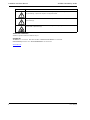
The following icons are used in this document
Convention
Description
Caution: This icon is used to indicate that there is a danger to equipment. The danger could be loss of data,
physical damage, or permanent corruption of configuration details.
Warning: This icon is used to indicate that there is a danger of electric shock. This may lead to death or
permanent injury.
Warning: This icon is used to indicate that there is a danger of inhaling dangerous substances. This may
lead to death or permanent injury.
Tradename statement
ADPRO is a registered trademark of Xtralis AG Pty Ltd.
Contact Us
The Americas +1 781 740 2223 Asia +852 2916 8894 Australia and New Zealand +61 3 9936 7000
Continental Europe +32 56 24 19 51 UK and the Middle East +44 1442 242 330
www.xtralis.com
ii
Doc. 13484_03
ADPRO VideoWall by Xtralis
Installation and User Manual
Contents
1 Introduction ......................................................................................................................................1
2 Scope .................................................................................................................................................2
3 Requirements ...................................................................................................................................2
3.1 System Requirements ........................................................................................................2
4 Installation ........................................................................................................................................3
4.1 System Configuration .........................................................................................................3
4.2 Firewalls ...............................................................................................................................3
4.3 At the VideoCentral Database Server ................................................................................3
4.4 VideoWall Licence ...............................................................................................................4
4.5 At the VideoWall PC ............................................................................................................6
5 VideoWall PC Configuration ............................................................................................................6
6 Starting VideoWall ............................................................................................................................9
7 Controlling the VideoWall .............................................................................................................. 10
7.1 Administrator Access ....................................................................................................... 10
7.2 Operator Access ............................................................................................................... 12
7.3 Interaction with VideoCentral .......................................................................................... 13
7.3.1 Alarm Operation ..................................................................................................... 13
7.3.2 Control of PTZ and Audio ...................................................................................... 13
7.3.3 Static Images on the VideoWall ............................................................................. 14
7.3.4 Camera Options ..................................................................................................... 14
7.3.5 Site Options ........................................................................................................... 14
7.3.6 Screen Saver Feature ............................................................................................ 14
Doc. 13484_03
1
Installation and User Manual
ADPRO VideoWall by Xtralis
2Doc. 13484_03
ADPRO VideoWall by Xtralis
1
Installation and User Manual
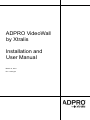
Introduction
VideoWall provides the facility to display multiple cameras on multiple monitors simultaneously.
The monitors show live video from any site configured with an ADPRO video transmitter.
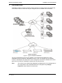
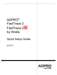
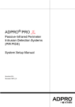
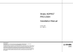
Figure 1: Typical VideoWall Installation
Up to four VideoWall licences may be installed on the VideoCentral Database PC. Each
VideoWall license will support a VideoWall PC which, in turn, can support up to four display
monitors. VideoWall is very flexible and can be configured to suit the PC hardware and monitor
types used, as well as the installation requirements of a particular site.
Note:
Doc. 13484_03
The monitor on the VideoCentral Database and Media Server PC is independent of
the configuration of the VideoWall itself and is managed through Display
Properties, under Windows' Control Panel.
1
Installation and User Manual
2
ADPRO VideoWall by Xtralis
Scope
This manual provides information on how to install and configure VideoWall for operation with
VideoCentral Gold.
3
Requirements
To use VideoWall functionality, the following is required:
•
•
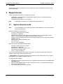
VideoWall is a licensed feature of VideoCentral Gold. A licence must be purchased to
enable this functionality.
VideoCentral Gold software V11.00 or later.
Note:
3.1
VideoWall functionality is not available with VideoCentral Lite.
System Requirements
Note:
To run VideoWall, the accompanying VideoCentral Database PC must also meet the
minimum specification.
Minimum VideoWall PC specification:
•
•
•
•
•
•
•
Processor: 2GHz dual core processor
CPU Memory: 1GB RAM
Motherboard: At least one PCI express slot for graphics card. For multi-graphics cards
support, a motherboard with multiple PCI Express slots is required
Graphics card: PCI Express Graphics cards to support required monitor layout with at least
256MB of memory
Network Port*: 1Gbps transmission rate.
OS: Win XP Pro
.NET 1.1 and 2.0 installed**
Minimum VideoCentral Database specification:
•
•
•
•
•
Processor: 2GHz dual core processor
CPU Memory: 1GB RAM
Network Port*: 1Gbps transmission rate.
OS: Win XP Pro, Server 2003
.NET 1.1 and 2.0 installed**
* Due to the speed requirements of video transmission, the physical network should also be
capable of supporting 1Gbps transmission rates.
** .NET Software: This software will need to be installed from the VideoCentral V11 (or higher)
DVD-ROM if it is not already installed on the PC.
To install the .NET software:
1.
2.
3.
2
From the menu of the VideoCentral Product Installation DVD-ROM, select the TOOLS and
UTILITIES button.
Open the folder labelled: Microsoft .NET Framework Version 1.1 Redistributable Package
and run the “dotnetfx.exe” file.
Then repeat this for the Version 2.0 folder.
Doc. 13484_03
ADPRO VideoWall by Xtralis
4
Installation and User Manual
Installation
Before installing VideoWall, the user must have available, as a minimum, the following:
•
•
•
4.1
VideoCentral Gold Version 11.00 (or higher) software
VideoWall Licence
At least two networked PCs; one for the VideoCentral Database (fitted with dongle) and
another for VideoWall use with at least one monitor.
System Configuration
The configuration of a VideoWall system has these guidelines:
•
•
•
•
•
•
•
•
4.2
All PCs in the system must be running the same version of VideoCentral (V11 or higher)
Up to four VideoWall PCs can be configured within a VideoCentral Gold System for a
maximum of 320 possible cameras
Each VideoWall PC requires a licence to be installed at the VideoCentral Database
Each VideoWall PC should be separate and not a User Interface PC or VideoCentral
Database PC
When a VideoWall licence is installed on a VideoCentral system that has one hardware
dongle, the system will support (up to) 24 remote sites via a mixture of network connections
and up to four serial (PSTN or ISDN) connections (eight serial connections available if used
with Server 2003)
Each additional hardware dongle, will allow the system to support a further 24 remote sites
The VideoWall Control Interface (that is accessed from the VideoCentral User Interface), is
used to manage the display layout of the cameras shown on the VideoWall monitors. The
configuration of the monitors attached to each VideoWall PC is, however, managed from the
VideoWall PCs themselves
Up to four monitors may be configured on each VideoWall PC. Each monitor can display up
to 20 cameras (cameos), therefore a maximum of 80 cameos is available to display the
video from all cameras located at all remote sites.
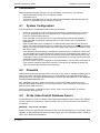
Firewalls
VideoCentral requires that Port 8005 TCP to be 'open' in any router or software firewall. Opening
of this port is best achieved by allowing the virus scan software to accept VideoCentral when
prompted to do so. The VideoCentral module(s) in question are called MD.exe, UI.exe, SPM.exe
and ADPROMEDIASERVER.exe.
Also, VideoWall uses 'ping' (ICMP) commands to communicate. Many firewalls and virus
programs block ICMP commands. To overcome this issue, use the firewall or virus interface to
grant access to ICMP Protocol.
For more information on firewall and virus access, refer to the documentation or websites
associated with these products.
4.3
At the VideoCentral Database Server
A VideoWall licence must be installed at the VideoCentral Database server. Refer to the ADPRO
Licensing Instructions manual for more information. The Licensing Instructions are available on
the website:
WEBSITE: www.xtralis.com/adpro
Existing versions of VideoCentral Gold must be shut down and upgraded to V11 (or higher). After
upgrade, the CMS Administrator enters the new license "key" for a VideoWall via the "Licensing"
option of the VideoCentral database.
Doc. 13484_03
3
Installation and User Manual
ADPRO VideoWall by Xtralis
The communications connections for VideoWall and VideoCentral are shared. To ensure that
alarm handling is not compromised, the VideoCentral Database Server manages the allocation
of communications between the VideoWall and the alarm handling capability of VideoCentral. A
specified number of connections (Session Handlers) can be reserved for alarm handling. See the
VideoWall Licence explanation below.
4.4
VideoWall Licence
VideoWall adds video surveillance capability to VideoCentral.
The installation of the first VideoWall licence enables each (and every) hardware dongle in the
VideoCentral system to manage 24 Session Handlers (instead of the normal eight Session
Handlers).
The extra sixteen Session Handlers may be shared between VideoWall and the alarm handling
capability of VideoCentral.
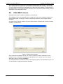
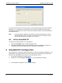
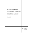
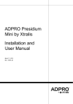
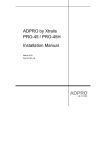
Figure 2: VideoCentral Licensing
At the VideoCentral Database server, the number of Session Handlers available for alarm
handling can be controlled by selecting any VideoWall licence in the list (up to four may be
displayed), and then selecting Configure.
The VideoWall Session Handler Allocation screen applies globally to all VideoWall licences. It is
now accessible to configure the Session Handlers.
4
Doc. 13484_03
ADPRO VideoWall by Xtralis
Installation and User Manual
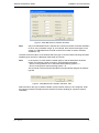
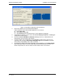
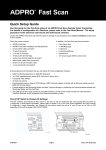
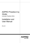
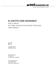
Figure 3: VideoWall Session Handler Allocation
Note:
Only one VideoWall license is required to increase the number of Session Handlers
to 24 for every hardware dongle. (If, for example, there were three dongles in the
system, the VideoWall licence would increase the number of session handlers
available to 72)
The tabs across the bottom of the window select the type of communication link being allocated.
Available types are PSTN, ISDN 64K, ISDN 128K and TCP/IP.
Note:
In the system, for each Session Handler (SH) PC that is fitted with a hardware
dongle, the following “serial connection” (PSTN/ISDN) limit applies:
- SH PC running Windows XP or Windows 2000 operating system = 4
- SH PC running Server 2003 operating system = 8
The remainder of the 24 Session Handlers are automatically assigned as network
type SH.
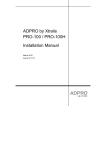
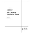
Figure 4: VideoWall Session Handler Allocation Tabs
Select the tab for the type of Session Handler (communication device) to be configured. Enter
the number of Session Handlers that are reserved for alarm handling (ie.cannot be used for
VideoWall)
Doc. 13484_03
5
Installation and User Manual
ADPRO VideoWall by Xtralis
In a purely TCP/IP network environment (with one hardware dongle and 24 Session Handlers
available) if “4” is entered on the TCP/IP tab, then four Session Handlers are reserved for
managing incoming alarms from sites. This leaves 20 Session Handlers (or Sites) available for
the VideoWall PC(s).
Note:
4.5
The serial Session Handlers are divided into Hunt Groups whereas the TCP/IP
Session Handlers exist in one group. If no Hunt Groups are configured, then all
serial Session Handlers are located in Hunt Group 0.
At the VideoWall PC
To install the VideoWall software on a VideoWall PC:
1.
2.
5
Select the VideoWall button on the DVD splash screen.
Follow the installation wizard to install VideoWall. Once the installation is complete, the
VideoWall and Configure VideoWall icons are displayed on the desktop.
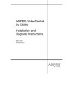
VideoWall PC Configuration
The configuration tool allows the CMS administrator to setup and manage a VideoWall PC. The
administrator can manage features such as the monitors to be used and which VideoCentral
Server PC the VideoWall PC will connect to. The administrator should:
6
1.
2.
Log into the VideoWall PC as Administrator
Double click on the Configure VideoWall icon on the VideoWall PC desktop.
3.
The VideoWall Configuration screen is then displayed.
Doc. 13484_03
ADPRO VideoWall by Xtralis
Installation and User Manual
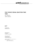
Figure 5: VideoWall Configuration with two Monitors
4.
5.
6.
7.
8.
Doc. 13484_03
Enter the IP Address of the VideoCentral Database.
If the IP Address of the VideoCentral Database PC is not known:
(a) select Start / Run.
(b) Type cmd and select OK.
(c) Type ipconfig at the command window. The IP Address is displayed.
If more than one monitor is to be used, select Access Display Properties -> Settings to
configure the monitor layout.
Check the Launch VideoWall on Windows start up check box if VideoWall should
automatically run each time the PC restarts.
A custom graphic can be displayed on the VideoWall monitors when a cameo is not
currently in use. Check the Use custom VideoWall logo and click Select to choose a
JPEG (JPG), bitmap (BMP), GIFF, TIFF or PNG file.
To change the quality of the images displayed on the VideoWall, use the Image Quality
slider. Moving the slider to the left or right adjusts the default quality by one level. The
default image quality for various multiple camera display options is as follows:
7
Installation and User Manual
ADPRO VideoWall by Xtralis
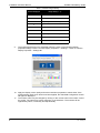
Table 1: Default Image Quality
Number of
Cameras Displayed
9.
Image Quality (1 - 7)
1
6
4
5
7
larger images = 5 smaller images = 3
9
4
10
larger images = 5 smaller images = 3
12
4
13
larger image = 5 smaller images = 3
16
3
20
2
The monitors displayed on the VideoWall reflect the setup of the Windows display
properties settings. Use the 'Access Display Properties -> Settings...' button to view the
Display Properties - Settings tab.
10. Apply the display colour quality and screen resolution properties to match those of the
monitors being used. Once these have been applied, the VideoWall Configuration screen
will again be displayed.
11. The monitor name may be changed by clicking on the current name in the bottom / left of
the screen. The name may have a maximum of 16 characters. The monitors will be
organised by name, numerically and alphabetically.
8
Doc. 13484_03
ADPRO VideoWall by Xtralis
Installation and User Manual
12. Click OK to finish and exit the Configuration screen.
6
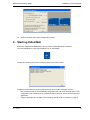
Starting VideoWall
Ensure the VideoCentral Database is running, with the VideoWall licence enabled.
On each VideoWall PC, click the VideoWall icon on the desktop.
A dialog box showing the version number appears on the first monitor:
Possible problems that may be encountered at this point include messages such as:
•
•
Doc. 13484_03
Not configured. Launch the VideoWall Configuration tool and close this application. If the
configuration tool is already running then bring that to the front, with focus and close this
application.
Program Applications Port 8005 TCP blocked by firewall (refer to Firewalls on page 3).
9
Installation and User Manual
•
•
•
•
ADPRO VideoWall by Xtralis
ICMP Protocol blocked by firewall (refer to Firewalls on page 3).
Cannot connect to the VideoCentral Server. Fatal. Halts the start up process.
Cannot obtain a licence. Fatal. Halts the start up process.
Cannot restore the defaults. This is the last known layout and connections of this VideoWall.
There may be problems such as:
No defaults present. Not fatal, message only, no defaults loaded.
Monitor configuration changed. Not fatal, message only, no defaults loaded.
Any of the above problems will be reported on the output pane and either stops the execution of
the VideoWall application or, if not fatal, the start up process will continue. Clicking the Close
button will shut down the VideoWall application.
7
Controlling the VideoWall
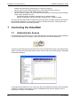
7.1
Administrator Access
Use Administrator privilege to log on to the VideoCentral User Interface that has been upgraded
to VideoCentral Gold V11 (or higher). At the User Interface, click the VideoWall icon.
A site list is presented down the left side of the screen; this lists all the sites in this VideoCentral
system. The tabs along the bottom align with the monitors that were named using the VideoWall
Configuration dialogue.
For FastScan transmitters only, one camera per site can be loaded and viewed on the VideoWall.
If FastVu or FastTrace transmitters are used, VideoWall has the ability to display up to the
transmitter’s maximum of 20 cameras.
10
Doc. 13484_03
ADPRO VideoWall by Xtralis
Installation and User Manual
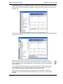
Configuration Example: It is decided that the first monitor on the VideoWall will need to display
six (6) video cameos permanently (for example cameras around the front / back doors etc.) Four
other cameos are to be reserved for operators to "park" their video. To do this, click on the "10way split" icon.
This not only changes the dialog display on the PC, but also the display on the VideoWall monitor
named as 'Srv1 Mon1'.
Selecting the site 'ABCD', will show a “spinning” symbol (shown at right) while the
system is getting the camera names from the remote site. This may take a few seconds,
as it is a network linkup. If using PSTN lines, connection times of 30-40 seconds may
be experienced.
Once VideoCentral has connected to that site and retrieved the camera names, they
are presented on the screen, allowing drag and drop on to the cameos on the right.
There is also drag and drop between cameos to exchange locations.
Alternatively, click the Site (blue symbol) and drag onto the VideoWall to display all
cameras. All cameras will be placed sequentially, up to the maximum number of splits
selected.
Doc. 13484_03
11
Installation and User Manual
ADPRO VideoWall by Xtralis
To remove a camera, drag and drop off the monitor surface or drag to the “bin”.
To complete the example, drag and drop the six required cameras to six cameos of
the VideoWall. The’ Lock’ checkbox in each of the six cameos may now be selected.
Note that the six cameras can be from a mix of remote sites.
As this is being done, the VideoWall monitor will display live video streams from the selected site
of the selected cameras.
Saving the VideoWall Configuration
Once configuration of the VideoWall is complete, the setup for Srv1Mon1 can be saved to a file
for easy recall.
The Save Monitor Settings tab is used to save and store the configuration.
The Load Monitor Settings retrieves the configuration file. Note that the correct monitor must
be selected when a Load Monitor Settings is performed.
A separate file can be saved for each named monitor.
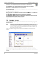
7.2
Operator Access
If logged in as an administrator, log out of the VideoCentral User Interface and log in again with
Operator privileges.
Note:
Logging into VideoCentral with Operator privilege does not allow the user to change
the configuration of the VideoWall, for example re-setting the lock feature of a
cameo locked by the Administrator, or changing the custom logo displayed on the
(currently unused) cameos of the VideoWall. These features require the use of the
Administrator or Installer privilege.
Launch VideoWall by clicking on the icon located on the sidebar of the VideoCentral User
Interface.
Note that the cameos that were locked by the CMS administrator now have a "lock" icon
attached. Camera images cannot be assigned to a cameo that is locked. Nor can cameras
already in use in a locked cameo be moved to another cameo, even if the new cameo location is
unlocked.
12
Doc. 13484_03
ADPRO VideoWall by Xtralis
Installation and User Manual
However, cameras that are not in use elsewhere may be dragged by an Operator into a cameo
that has not been locked (last 4 cameras in this example).
Also note that when logged in with Operator privilege, if VideoWall cameos have been locked by
Administrator or Installer privilege, then the screen split options are ghosted and cannot be
altered.
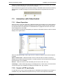
7.3
Interaction with VideoCentral
7.3.1 Alarm Operation
When an alarm occurs at a remote site, VideoCentral will place the alarm on the User Interface
for action by the Operator. Selecting the alarm from the All Sites List will cause all cameras for
the respective site to be displayed on the VideoWall with a highlighted red border and the last
frame displayed as a still image.
Once the alarm has been acknowledged by the Operator, VideoWall will return to the live camera
display in the original cameo.
When the VideoWall dialog is open, right click on a camera of interest. There are three options
available:
Open in VideoCentral - VideoCentral will connect to that site and the camera of interest is
displayed at the VideoCentral User Interface. If another operator has the respective site selected,
then this function is not available.
Remove - Takes the camera off the VideoWall (same function as the “bin” icon).
Load Image - Loads a fixed image (logo) to be displayed in the cameo when it is unused. Most
common file types are acceptable for loading (for example .bmp, .jpg, .png etc)
7.3.2 Control of PTZ and Audio
If a site with PTZ or Audio control is assigned to the VideoWall, these features will no longer be
available to any other VideoCentral system that may connect to the respective transmitter.
Doc. 13484_03
13
Installation and User Manual
ADPRO VideoWall by Xtralis
7.3.3 Static Images on the VideoWall
Red Border - While cameras are being accessed manually by an operator (for example during
an alarm), a reduced (size) cameo is highlighted with a red border and the last frame displayed.
Grey/Green Background - the background colour is displayed while images are being loaded
from a site.
Red Background - Unable to retrieve video from site (90 seconds has elapsed)
Yellow Background - Site has been disconnected (9 minutes has elapsed)
Logo display - No camera is associated with the cameo.
Blue Background - Camera has lost signal. Camera in a No Video state.
7.3.4 Camera Options
Right-click on a Camera Name on the (left-hand) list will display two options:
Locate - this option provides an easy method of finding the camera on the VideoWall. When
selected, the cameo name will flash (inverse video) to highlight its position (or positions) on the
VideoWall.
Remove - Takes the camera off the VideoWall (same function as the “bin” icon).
7.3.5 Site Options
Right-clicking the Site Name on the list will display the following options:
Locate - this option provides an easy method of finding the cameras (belonging to that Site
Name) on the VideoWall. When selected, the cameras’ cameo name will flash (inverse video) to
highlight its position (or positions) on the VideoWall.
Remove - Takes the Site off the VideoWall (same function as the “bin” icon).
Reconnect - Causes the site to be reconnected to the VideoWall when a yellow background is
displayed.
7.3.6 Screen Saver Feature
In operational mode, the whole image is rotated clockwise (by five pixels) to help reduce monitor
screen burn.
14
Doc. 13484_03