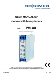
1
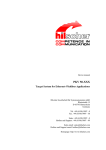
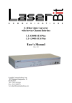
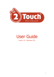
DISPLAY UNIT Four channel sensor display with touch screen control 3 The Display Unit The Display Unit is a module to display up to 4 sensor signals. Applications are laboratory experiments or experimental series. • • • • four sensor inputs, free programmable units (such as mW/cm2, lux, °C, counts, Pa etc.) programming and calibration via touch screen or PC software programmable alarms – red coloured value and buzzer alarm, two programmable relays suited for cleanrooms Specifications of the Display Unit Parameter Value Unit 4 - Panel dimensions (BxH) 150 x 120 mm Installation Dimensions 127 x 107 x 50 mm IP65 - Operating temperature -10….+50 °C Storage temperature -10… +50 °C 24 VAC or VDC Power consumption at 24 VDC 0,12 W Weight 0,240 kg f Ports Number of probe inputs (0…10VDC or (0)4…20mA) Parameters of the housing Degree of protection, front side 2 Additional technical data Power supply Rev. 1.0 page 1 Manufacturer: sglux GmbH, Max-Planck-Str. 3, D-12489 Berlin, Tel. +49 30 5301 5211, Fax +49 30 5301 5209 mail: [email protected] - web: www.sglux.de - WEEE No. DE 76297302 DISPLAY UNIT Four channel sensor display with touch screen control 3 Display Examples Rev. 1.0 page 2 Manufacturer: sglux GmbH, Max-Planck-Str. 3, D-12489 Berlin, Tel. +49 30 5301 5211, Fax +49 30 5301 5209 mail: [email protected] - web: www.sglux.de - WEEE No. DE 76297302 DISPLAY UNIT - USER MANUAL TABLE OF CONTENTS 1. Basic requirements and safety 2. Technical specifications 3. Wiring diagram 4. Jumper settings 5. Quick start 6. Operating procedure 7. Alarm 8. Counter 9. Menu Structure 10. Configuration check 1. Basic Requirements and safety: The manufacturer is not responsible for any damages caused by inappropriate installation, not maintaining the proper Technical condition and using the unit against its destination. Installation should be conducted by qualified personal. During installation all available safety requirements should be considered. The fitter is responsible for executing the installation according to this manual, local safety and EMC regulations. The unit must be properly set-up, according to the application. Incorrect configuration can cause defective operation, which can lead to unit damage or an accident. If in the case of a defect of unit operation there is a risk of a serious threat to the safety of people or property additional, independent systems and Solutions to prevent such a threat must be used. The unit uses dangerous voltage that can cause a lethal accident. The unit must be switched off and disconnected from the power supply prior to starting installation of troubleshooting (in case of malfunction). Neighbouring and mating equipment must meet the requirements of appropriate standards and regulations. Concerning safety and be equipped with adequate anti-overvoltage and antiinterference filters. Do not attempt to disassemble, repair or modify the unit yourself. The unit has no user serviceable parts. Units, in which a defect was stated must be disconnected and submitted for repair at an authorized service centre. In order to minimize fire or electric shock hazard, the unit must be protected against atmospheric precipitation and excessive humidity. Do not use the unit in areas threatened with excessive shocks, vibrations, dust, humidity, corrosive gasses and oils. Do not use the unit in explosion hazard areas. Do not use the unit in areas with significant temperature variations, exposed to condensation or icing Do not use the unit in areas exposed to direct sunlight. Make sure that the ambient temperature (e.g. inside the control box) does not exceed the recommended values. In such cases forced cooling of the unit must be considered (e.g. a ventilator) The unit is designed for operation in a non industrial environment and must be used in this way. 2. Technical specifications: Power supply Power consumption Input impedance at mA Input impedance at V Impedance digital input Display Protection class Dimensions Mounting hole Casing type Ambient temperature Humidity Analog input Digital input Wiring Input Output Ethernet USB SD input GND DC 24V+/- 20% of AC 24V +10% / –20% 12VA 150 Ω 15 kΩ 3 kΩ 3.5” TFT display with Touch screen Front IP65 / Wiring IP00 150 x 120 x 50 mm 127 x 107 mm Panel, snap in -10°C tot +50°C 5% till 90% non-condensing 0…10VDC , 0/4…20mA (via jumper selectable) logic 0 = 0-6V / logic 1 = 18-24V (max. 1000 Hz) Via connectors on the back 4x Analog, 4x digital, RS485, Modbus RTU Relays (2x): 125VAC -0.5A 30Vac-1A 60VDC -0.3A /5msec RS-232 RS-485 +24VDC (2x) (max. 0.5A) +3.3VDC (max. 20mA) Standard 10/100Mbaud Standard PC compatible Micro SD, standard PC compatible Is used with power supply and inputs The display can show 1 up to 4 inputs simultaneously (user selectable). These inputs can independently generate visual and acoustic alarm. At the visual alarm the background color will change from green (no alarm) to red (alarm), at an acoustic alarm a buzzer will sound (if switched ON). The sound of the buzzer can be suppressed, while the background color will not change. The digital inputs can be used as “door counter” via a 24V pulse (if necessary supplied by the unit {max. 0.5A}), alarms can be set as well. The counter can count up to max. 9999 and can be reset to “Zero” manually. All settings can be made via the touch screen, but you need to set the jumpers on the back to select the proper analog input (mA or V). The unit has the possibility to display a status message, this can be done by activating a digital input and for example the message “Out of Service” will be displayed. You can also select the background color and buzzer ON/OFF. 3. Wiring diagram: Ethernet SD card USB RS-232 Analog input Reference voltage (3.3V) Digital output +24V out Digital input RS-485 +24V out Jumpers ( mA or V input) Power supply 4. Jumper settings: With these settings you can select 0…10VDC or (0)4…20mA as analog input. If no jumpers are set the input will be automatically 0…3.3V (Vref.) These settings must be set in the “input type” menu as well The jumpers ALWAYS must be set!!! jumpers must be changed without power supply connected to the device !!! 5. Quick Start: <2 sec. > 5sec. 6. Operating procedure: If the unit is connected to the power supply (24VDC/AC) the following screens will appear. The data is collected from the SD card. After the startup the unit automatically will show the measuring modus (standard 4 input screens) By touching the screen for minimal 5 sec. the PIN menu will appear, where the standard PIN-code “0000” needs to be entered (PIN-code stays active for 1 minute) The PIN-code can be changed via “PIN change” (in the main menu) into your own 4-digit code = clear input = manufacture info = EXIT (back to measuring modus) If the PIN-code is incorrect the code will appear in RED, try again. = clear input = manufacture info = EXIT (back to measuring modus) If no action is taken for 20 seconds the unit will return to the measuring modus. If the PIN-code is correct you automatically enter the input configuration of the screen that has been touched (in the example Analog 1 is selected). = current screen position = by touching this field you can switch to other inputs = EXIT, back to previous screen = to the main menu Screen layout: Where the selected input needs to be displayed. = current screen position = Okay, back to previous screen = Cancel, back to previous screen Input type: What input type is applied Disabled: No input is required Analog: (remind the JUMPER setting !!!) Choose port number to be used, and choose mode (raw value, 0..20mA, 4..20mA, 0..10VDC) Digital: Choose port number to be used Modbus: The input value is comming from a Modbus master module = current screen position = Okay, back to previous screen = Cancel, back to previous screen Description: Which text needs to be displayed Top Left- and Top right of the selected screen = current screen position = Okay, back to previous screen = Cancel, back to previous screen Measuring range: setting of minimum (Min) and maximum (Max) value, decimal point ( Yes / No ) and Unit (for example °C) Actual Status: If for example digital input 4 is set, the text will be displayed (for example “out of service” ) = current screen position = Okay, back to previous screen = Cancel, back to previous screen The actual status can be used for example when room is temporary out of service. NOTE !!! Alarms are DISABLED The buzzer ON / OFF can be selected The background color can be selected Alarm: setting of HIGH and LOW Alarm, Hysteresis, Delay , Buzzer en Relays = current screen position = Okay, back to previous screen = Cancel, back to previous screen Enabled = alarm ON / OFF Value = value at which the alarm is activated Hysteresis = difference value between status change of the alarm Delay = alarm delay in seconds Buzzer = Relay 1/2 = ON / ON / OFF OFF at alarm status at alarm status NOTE 1 : If a DIGITAL input is selected: - When all setting are done, touch and you will enter the parent menu the “Input type” is not active At the “measuring range” the unit only can be set At the “Alarm” only the High alarm can be set NOTE 2: If a Modbus input is selected: - A mobus failier alarm can be set in the same way as done by the low and high alarms. No value can be set No hysterese can be set Touch and the next screen will appear if changes have been done else you will return to the measuring mode. = save changes, back to measure modus = don´t save changes, back to measure modus = Cancel, back to previous screen If is touched instead of , than you will enter the `Main Menu` where further settings can be done, the previous setting will be saved after leaving the `Main Menu`. Screen Layout: normally the layout is depending on the amount of sensor connected, you can also choose if you want the measured values ( 0.0 C ) or only the unit ( C ) to be displayed. = Okay, back to previous screen = Cancel, back to previous screen Configure Input: here you can choose which input you want to configure. = previous screen position = Cancel, back to previous screen General settings: - Device Name (usually it is called 123-2Touch along with the serial number of the devise) - Language selection (Nederlands / Deutsch / English) - Setting of the Buzzer volume (in steps of 20%) - Setting of the LCD brightness (in steps of 10%) = Okay, back to previous screen = Cancel, back to previous screen Date and Time: = Okay, back to previous screen = Cancel, back to previous screen - each item can be changed by touching the desired field. - when ready touch the green mark at the bottom. - for undo touch the red cross Network Settings (Only for Version 1.7.2 and up) = Okay, back to previous screen = Cancel, back to previous screen - The mode can be changed to DHCP or STATIC IP. - at DHCP the unit will receive an IP number from the connected router - at Static IP you can enter your own required IP address, Subnet mask and default gateway settings. Modbus Settings (Only for Version 1.6.1 and up) = Okay, back to previous screen = Cancel, back to previous screen - The mode can be changed from disabled to Modbus Slave. - The Interface can be selected as RS232 , RS485 or Ethernet, whereby at the RS232 and RS485 settings the required Baud rate and Address can be set. Change PIN code: here you can change the PIN code a 4-digit PIN-code of your choice. = Okay, back to previous screen = Cancel, back to previous screen By touching the PIN code field you get the below screen for changing the PIN code = Okay, back to previous screen = Cancel, back to previous screen Factory settings: here you can go back to the standard factory settings. = Reset to factory settings, back to measure modus = Reset to current settings, back to measure modus = Cancel, back to previous screen Counters will be set back to “0” System information: Here you find information about the manufacturer = Okay, back to previous screen At the bottom left you find the serial number (in this example SN: 0000004) and software version (in this example VER: 1.03c) NOTE: By touching the numerical or Alfa numerical field the next screens will appear. (as example the “Measuring range” is chosen) Capital letters Punctuation marks Calculator function If during configuration the background of the input field turns “RED” the added value is not correct. Example: - the min. value is higher than the max. value - the alarm limits are outside the measuring range NOTE: 1x push = SHIFT function 2x push = CAPS LOCK function 7. Alarm: If the measuring signal exceeds the set alarm limit the background color changes from “green” to “red” , the buzzer also will be activated (if switched ON). If the measuring signal gets within the alarm limit the background color changes back to “green” and the buzzer will be deactivated. During the alarm situation the buzzer can manually be deactivated by touching (< 2 sec.) the field in which the alarm has appeared, the below screen will appear. = save changes, back to measure modus = don´t save changes, back to measure modus = Cancel, back to previous screen The background color stays “red” during alarm situations even when the buzzer is deactivated. 8. Counter: The digital inputs can be used as door counter, every time the digital input gets a logical “high”, counts will be increased. By touching the “counter field” (< 2 sec.) the below screen will appear. = reset counter, back to measure modus = don´t reset counter, back to measure modus = Cancel, back to previous screen If also alarm limits have been set and this limit is exceed the below screen will appear if you touch the “counter field” (< 2 sec.) during this alarm situation. = Reset Buzzer YES / NO = Reset Counter YES / NO = Cancel, back to previous screen 9. Menu Structure: 10. Configuration check The unit automatically checks for errors after setup. This to exclude that no conflicting data is entered (for example: alarm limits are outside the measuring range etc.). If conflicting data was entered you have already been warned by the “RED” background color of the input field and this warning has been ignored. By returning to the measuring modus the below notification will appear for 30 seconds. (down counter on the right) By touching the screen >5 sec. and entering the correct PIN code the below screen will appear; Here the incorrect setting will show. By touching them you enter the setting menu so the error can be solved.