1
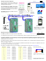
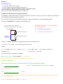
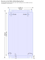
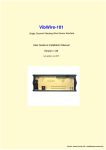
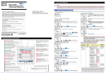
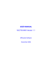
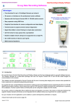
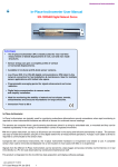
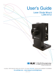
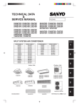
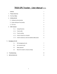
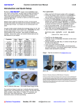
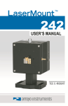
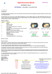
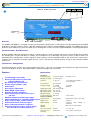
GEOTECHNICAL INSTRUMENTATION
VibWire-108-Modbus
8 Channel Vibrating Wire Sensor Interface -Using Modbus over 485
Pin-outs
Model No. VibWire-108-modbus
0V /Gnd
+ 12V
485 -
485 + / SDI-12
NPN-4
NPN-3
NPN-4
485 + / SDI-12
NPN-3
+ 12V
Overview
485 -
0V /Gnd
Terminal Port
Cover
2461.7
Model
VibWire-108-Modbus
The VibWire-108-Modbus is a rugged, versatile, general purpose vibrating wire sensor interface for connection directly to SCADA
applications and data recorders across a RS-485 network using the industry standard Modbus protocol. The VibWire-108 range
of devices gives third party systems the ability to use vibrating wire sensors even if the original hardware is not designed to do so.
Sensor Excitation - Auto Resonance
All of the VibWire-108 range of interfaces utilises an auto-resonance sensor excitation and measurement technique for activating
the vibrating wire sensors and taking a reading. This technique has the advantage over pluck systems in that no prior User
knowledge of the vibrating wire sensor is required. Auto-resonance sensor excitation minimises the strain on the sensor coil as
it always acts to maximise the output signal from the sensor, and does this without wasting energy on out of band excitation
frequencies.
Terminal Port - Configuration
A terminal port menu system is be used to configure this device. The User can configure the instrument to send measurement
values in Hz, Digits or SI units. No programming is required to configure this instrument.
Features
Specifications
Description
Frequency display
Vibrating wire inputs
Scan time
8 x 4 Vibrating wire sensor inputs
Resolves the VW signal to less than 0.01 Hz
(industry standard 0.1 Hz)
Gas discharge tube sensor protection
Line resistance
Real-time frequency display - 5 digit
8 Analogue Inputs
Audible output
Auto-resonance VW excitation
Lightning protection
VW excitation range
Modbus RS-485 network support
VW excitation mode
Automatic VW sensor configuration
Operating voltage
Digital communications to remove noise sources
Ceramic loudspeaker
and errors.
Power Consumption
Simplified configuration and data logger support.
Industry standard protocol - supported by SCADA systems Scanning mode
Display mode
Output - Frequency, Digits, SI Units, Temp Deg C
Modbus RS-485
Steinhart-Hart thermistor linearisation support
Options 2 Independent thermistor configuration
Slave ID
Integrated polynomial linearisation - quadratic Support
Software
direct from VW sensor calibration data sheet.
VW sensor linearisation
Temperature sensor
linearisation
Specifications may be changed without notice
Web Address: http://www. aquabat.net
5-segment display
8 x 4 wire inputs
2 - 24 Secs
Resolution 0.1 Hz
1 to 8 channels depending on
sensor operation.
up to 2K ohms
0 - 2.5V DC
3.3K / 10 K
Gas discharge tube
400 - 6 K Hz
auto-resonance
9 - 18V DC
VW sensor
0- 2.5V DC
thermistor
20 mA Typical
60 mA
2.2 mA
1
Duration 24 Seconds - 3 Sec /chan
continuous
Continuous while waiting for
commands
Max nodes on a 485 network
Quadratic
Y = A + BF + DF2
Steinhart-Hart
User-selectable via terminal port
[email protected]
selector switch
Copyright Keynes Controls Ltd
2015-2016
VW sensor Inputs
Speaker Selection Switch
+ RS-485/ SDI12
- RS-485
+ RS-485/ SDI12
- RS-485
12 DC
12 DC
Gnd/0V
Gnd / 0V
RS-485 Network Connection
Terminal Port
The VibWire-108 interfaces supports the full 4 wire gauge
input and can use any in-built thermistor temperature
sensor.
Part Numbers:
VW-108-Modbus
USB-485
VibWire-108 with RS485 Digital Port
USB to RS-485 media converter
All of the vibrating wire sensor interfaces and digital
network port are protected by gas discharge tube in order
to prevent damage by local lightning strikes.
Measurement Data:
Number of channels
VW sensor coil resistance
8 x 4-wire VW inputs - user-selectable
to 2K Ohm (standard) - other ranges on request
Distance of VW sensor to interface
Frequency range
0 .. 10 Km depending on cabling.
400 - 6 KHz (standard) - other ranges on request
Frequency resolution accuracy
Long-term stability
32-bit resolution 0.001 Hz
± 0.05 % FS max. (Per year)
Temperature range
- 50 to 70 degC
Temperature resolution
0.1 oC +/- 0.2 deg thermistor
Temperature accuracy
± 0.2 oC / 0.2 oF RS-485 version only
A half-bridge ratio-metric measurement . Value returned in mV.
Is used for temperature compensation on VW measurements.
2.5V DC 50 ppm /degC
10K Ohm 0.1 % completion resistor (Standard)
3.3K Ohm on request
Freq (Hz)
temperature (mV)
5 digit - 0.1 Hz
Thermistor measurement
Thermistor excitation
Input resistance
Units
Display only - resolution
Electrical Data:
10 K Ohm standard 3.3 K Ohm on request
Voltage supply
RS-485 10.5 to 16V DC
Current compensation RS-485 option only:
Typical values are @ 12V DC excitation
idle mode
active / measurement
2.2 mA
10 mA
60 mA
data transmission
including frequency display
These values may change slightly between sensors. Use figures as a guide only.
Measuring time:
warm up
response
Length of data lines RS-485
RS-485 address mode
General Data:
500 ms
3 seconds per channel depending on the VW sensor being used (Typical)
0 .. 1000 m
Supports enhanced addressing 0 .. 9
Dimensions (mm)
L =260
Material
Operating Temperature
Data Types
Digital port
CE conformity
Powder - coated aluminium
-20 to + 65 Deg C
W = 127
Weight
500 g
A .. Z
D = 38
RS-485, 9600 Baud, 8-bit, 1 stop bit, even parity - other speeds on request
CE conformity according to EN 61000-6
Digital communications
Terminal port
9-way male - 9600 Baud 8 data, no parity, N stop
RS485 port - Modbus
9600 baud, 1 start bit, 8 data, even parity bit, 1 stop
Tel: 0044 118 327 6067
Copyright AquaBat
2015-2016
1 2 3 4
Network Connection & Expansion
1
2
3
4
RS-485 -
+10 V DC
Gnd
SCADA Application
with Modbus Client
RS-485 +
The image opposite shows how the VibWire-108Modbus interface is connected to the USB-485Pro isolated media converter.
485 Network
The USB-485-Pro is the simplest device to be
can be used with this product as it not only
converts the 485 network to USB for reading on
a PC/Laptop, but also can power up-to 2 devices
directly from the USB port.
+
+ RS-485/ SDI12
- RS-485
External Power
Supply Port
Any SCADA system running a Modbus Client can
talk to the devices are
Part No. USB-RS485-Pro
Isolated RS-485 to USB media converter
Part No. VibWire-108-485
8 channel Vibrating Wire Sensor Interface with
RS-485 digital network.
+ RS-485/ SDI12
- RS-485
12 DC
12 DC
Gnd/0V
Gnd / 0V
12 - 16 V DC
Connect external power
supply if the maximum
current for the number
of devices on the RS485
network exceeds 85 mA
RS-485 Network Connection
RS485 +
The same port configuration
on all models of this instrument
RS485 +
0V /Gnd
+ 12V
485 485 + / SDI-12
NPN-4
NPN-3
NPN-4
NPN-3
485 + / SDI-12
485 + 12V
0V /Gnd
Part No. Hub-6-Port
Terminal Port
The expansion hubs are supplied by
Keynes
Controls
to
simplify
installation of multiple the instruments
into enclosures and panels.
Network Connection & Expansion
2 Bytes
Floating Point Data Value
The Modbus operations are transparent over the 485 network.
High Word
2 Bytes
Low Word
The USB-485-Pro media converter is shown in the diagram above, however any other similar device can be used.
The VibWire-108-Modbus instrument operates as a master /slave system where the SCADA system or data recorder is the master
and the instrument acts as the slave. The device scans the input channels once powered and updates the data registers after
completing any new measurements.
The number of channels scanned, and so the time taken to make a complete scan is set directly into the instrument via the push
buttons or using the terminal port.
Like all other Modbus products use a series of registers to hold measurement data. These registers are updated are after each
scan and data is sent to the Master on receipt of the
The registers are updated are after each scan and data is sent to the Master on receipt of the FC=04 command.
Address Offset
Parameter
Description
Address Offset
Parameter
Description
0
Chan-0 Freq
High Order word
16
Chan-0 Temp
High Order word
Low order word
17
High Order word
18
Low order word
19
Chan-2 Freq
High Order word
20
Low order word
21
Chan-3 Freq
High Order word
22
Low order word
23
High Order word
24
1
2
Chan-1 Freq
3
4
5
6
7
8
Chan-4 Freq
Low order word
25
High Order word
26
Low order word
27
Chan-6 Freq
High Order word
28
Low order word
29
Chan-7 Freq
High Order word
30
Low order word
31
9
10
Chan-5 Freq
11
12
13
14
15
Sensor Connection Circuit
Figure 14A
Low order word
Chan-1 Temp
High Order word
+
Therm
-
Low order word
Chan-2 Temp
High Order word
Chan-3 Temp
High Order word
+
Sense
-
Low order word
Earth
Thermistor
VW-108
Low order word
Chan-4 Temp
High Order word
Low order word
Chan-5 Temp
High Order word
Chan-6 Temp
High Order word
Chan-7 Temp
High Order word
The diagram above shows how the VW sensor is
connected to a VibWire-108 input channel in 4 x Wire
mode.
Low order word
Low order word
Low order word
The tables below show how the registers
holding the VibWire-108 data is stored.
Response:
03 04 04 000A F8F4
03: The slave address (03 = 03 hex)
04: The function code (read analogue input registers)
02: The number of data bytes to follow (2 registers, 32-bit floating-point)
0000: The contents of register 30001, first frequency output
F8F4: The CRC (cyclic redundancy check - this will vary)
Temperature Value Conversion to Engineering Units
The following section details how the instrument determines thermistor resistance values for a vibrating wire thermistor
connected to the temperature input of the device.
The current version of the instrument firmware only stores 2 different temperature sensor configuration options.
Refer to the ‘User Manual’ for setting up the thermistor inputs,
The VibWire-108-mobus uses 2.4 V excitation for
the sensor thermistor.
The circuit below shows the VibWire-108
temperature input with pull-up resistor completion
2.4V Excitation
Vtherm = Voltage across thermistor
VR
VR
3300 Ohm Pull-up resistor
= Voltage across pull up resistor
A
VibWire-108
Temp Output
Level in mV
Vtherm
Vibrating Wire Thermistor
0V
Example. A VibWire-108 provides an output temperature value of 1086 mV then
I therm = (2.4 - V therm) / 3300
where 3300 = pull-up resistor value
therefore
I therm = ( Excitation volt - V therm ) / 3300(Pull-up Resistor) =
(2.4 - 1.086) / 3300 = 1.414 / 3300 = 0.398 mA
using Ohms Law
Note 1086 mV = 1.086 Volts
The Resistance of the Thermistor is calculated
R therm = V therm / I therm = 1.086 / 0.000398
=
2727.4 Ohm
Now 2727.4 ohms is the resistance of the thermistor at the at temp (T)
Temperature Conversion
The thermistor resistance value is converted to temperature using the Steinhart-Hart Equation.
T=
1
where T = absolute temperature in Kelvin R therm in Ohms.
C1 + C2 . ln\Rtherm + C3(lnRtherm
)3
Conversion to Deg C is
T(C)=
1
C1 + C2 . ln Rtherm + C3(lnRtherm
- 273.15
)3
The sensor data sheet will show for the thermistor a calibration equation similar to that below. The values for the parameter
C1, C2, & C3 will be listed.
(1/T) = C1 + C2. Ln(Rtherm ) + C3 . Ln(Rtherm ) 3 - 273.15
Example
In Vibrating Wire sensors is the 44005RC Precision Epoxy NTC Thermistor is commonly used for temperature monitoring
applications.
The data sheet for this product can be downloaded at
http://www.aquabat.net/downloads/1350009-2.pdf
– The thermistor data sheet is valid to 11/12/2013
refer to the manufactures data sheet for the latest information.
An example Excel spreadsheet that demonstrates the temperature calculations can be downloaded at
http://www.aquabat.net/downloads/ThermistorWorksheet.xls
Example
The VibWire-108 is can be set to give ratiometric or mV temperature values from the built in thermistor of a vibrating wire sensor.
depending upon the sensor configuration. Ratiometric values are calculated between the 3300 Ohm pull up resistor and thermistor resistance and is value between 0 – 1. The Vibwire-101 has returned a value of 0.663 from the thermistor.
In the spreadsheet below the VW-108 gives a temperature value (Ratiometric) of 0.663. The constants A, B and C are from the
calibration data sheet. The spreadsheet below shows the temperature to be 7 Deg C,
ThermistorWorksheet.xls Screen image
Calculation of temperature based on voltage ratio
Voltage ratio
0.663
Input
Excitation (Ohm)
3300
Fixed
Thermistor resistance
6905
Calculated
Thermistor R0
3000
Thermistor property
A
1.41E-03
Thermistor property
B
2.37E-04
Thermistor property
C
1.02E-07
Thermistor property
Inv Temperature
3.57E-03
Temperature (Celsius)
7.0
Steinhart-Hart Calibration
Parameters obtained from
calibration data sheet.
Calculated value
Temperature value
Terminal Port Menu System
Terminal Port Connection
Null modem cable
The terminal port menu system enables the the VibWire-108 to be fully
configured using a simple pull down menu system.
All the inputs can be individually setup and the
results supplied in Engineering SI units. No
programming is required to configure this device.
Thermistor Type-1 Option
USB-RS232
Converter
Warranty Information
The information in this document is subject to change without notice. Keynes Controls Ltd. has made a reasonable effort to be sure that the information contained herein is current and
accurate as of the date of publication.
Keynes Controls Ltd. makes no warranty of any kind with regard to this material, including, but not limited to, its fitness for a particular application. Keynes Controls Ltd will not be liable
for errors contained herein, or for incidental or consequential damages in connection with the furnishing, performance or use of this material.
In no event shall Keynes Controls Ltd . be liable for any claim for direct, incidental or consequential damages arising out of, or in connection with, the sale, manufacture, delivery or use
of any product.
Last updated Sept 2015
Dimensions of the VibWire-108 Back Mounting Panel
The image below shows the dimensions of the back mounting panel for the VibWire-108 range
of vibrating wire sensor interfaces.