1
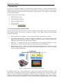
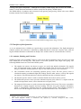
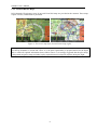
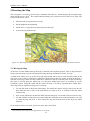
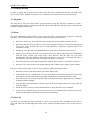
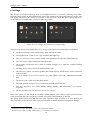
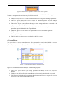
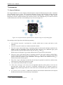
NESIS II User’s Manual 1. Introduction First of all, we would like to thank you for purchasing our product. NESIS is a complex instrument and we strongly recommend reading the manual before using NESIS. The introduction chapter contains some general information about the instrument and principles of the operation. Later chapters describe NESIS use and reveal the details. You may be also interested in reading: NESIS Purchase Guide, NESIS Installation Manual, DAQU Installation Manual, MAGU Manual, our web page www.kanardia.eu. 1.1 General Information about NESIS NESIS consists of electronic units which work closely together to bring flight, engine and fuel information onto graphical display. The system is presented on figure 1. The system consists of the following electronic components: Engine monitoring unit (DAQU) – used to connect the engine, fuel and electric sensors. Airu (AHRS and GPS unit) – further on referred as AHRS unit – as an inertial navigation unit aided by the GPS and pressure sensors, AHRS unit provides attitude, position and velocities. AHRS unit is hidden inside the NESIS Primary display. Mabu unit – is a hidden unit and serves as motherboard for the embedded computer, as a data logger and as a CAN bus interface. Mabu is an integral part of any NESIS display. NESIS Primary display – presents all relevant information that appears on the CAN bus in a pilot friendly form on a large LCD screen. Most of this manual describes how to access, read and interact with the NESIS display. Figure 1: Illustration of minimal NESIS configuration. The NESIS system can be easily extended into a much more complex form, shown on figure 2. We achieved this by introducing CAN bus for the communication between the units. The CAN bus does the magic of the all possible known and unknown future extensions. Imagine the CAN bus as a kind of computer network. Just like new computers can be easily connected to the network, we connect all new devices to CAN. This allows introduction of secondary NESIS display, autopilot, weather service, external 5