1
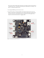
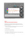
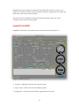
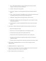
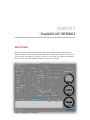
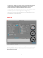
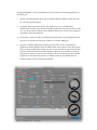
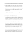
MOUNTING THE FRAME IMU
There are two options for placement of the second IMU: below the YAW motor and above
it.
If the sensor is placed above the YAW motor, it helps to stabilize ROLL, PITCH and YAW.
The system in this configuration becomes less stable during long work, however, because
the frame heading, estimated from the second IMU, may drift with time, and autocorrection may not work in all cases. If the sensor is placed below the YAW motor, it does
not help YAW axis stabilization but works more reliably.
Like the main (camera) IMU, the frame IMU may be mounted in any orientation, keeping
its axis parallel with the motor axes.
CONFIGURING THE FRAME IMU
To configure the frame IMU, first set its location in the “Advanced” tab, “Sensor” area.
Write settings to the board and go to the “Basic” tab. Select the “Frame IMU” button. If the
frame IMU is connected properly, this button becomes active and it means that all IMU
settings in the software now affect the frame IMU. Change sensor orientation (axis TOP,
RIGHT) and write the settings to the board, if necessary. After the board restarts, calibrate
the accelerometer and gyroscope like you did for the main IMU. For the accelerometer, you
can choose simple calibration or extended 6-point calibration.
You will notice that the right Control panels are now displaying angles for the frame IMU
and not the main IMU. Also, in the “Realtime Data” tab, the accelerometer and gyroscope
data is now for the frame IMU. Ensure the orientation of the frame IMU sensor is properly
configured, and check its calibration in the same manner you did for the main IMU.
RADIO CONTROL (RC)
Connecting a Remote Control system to the gimbal is optional. A configuration that
includes a RC system will allow control and aiming of the gimbal separately from the direct
physical movements of the gimbal unit.
RC INPUT MAPPING – In this section you can assign hardware RC inputs to virtual control
channels. There are four hardware inputs provided on the board for RC connections,
which you can assign to control any of three channels, one for each axis, and one
command channel. If control for an axis is not needed, leave the option as “no input”.
!
"24


![[DYS 3 Axis Gimbal User Manual]](http://vs1.manualzilla.com/store/data/005821240_1-6054c49231c96ddf730544e81a975eb9-150x150.png)